EP2196319A1 - Système pour imprimer un livre sur des pages pré-reliées - Google Patents
Système pour imprimer un livre sur des pages pré-reliées Download PDFInfo
- Publication number
- EP2196319A1 EP2196319A1 EP09251767A EP09251767A EP2196319A1 EP 2196319 A1 EP2196319 A1 EP 2196319A1 EP 09251767 A EP09251767 A EP 09251767A EP 09251767 A EP09251767 A EP 09251767A EP 2196319 A1 EP2196319 A1 EP 2196319A1
- Authority
- EP
- European Patent Office
- Prior art keywords
- page
- printing
- pages
- printable
- stack
- Prior art date
- Legal status (The legal status is an assumption and is not a legal conclusion. Google has not performed a legal analysis and makes no representation as to the accuracy of the status listed.)
- Granted
Links
Images




Classifications
-
- B—PERFORMING OPERATIONS; TRANSPORTING
- B41—PRINTING; LINING MACHINES; TYPEWRITERS; STAMPS
- B41J—TYPEWRITERS; SELECTIVE PRINTING MECHANISMS, i.e. MECHANISMS PRINTING OTHERWISE THAN FROM A FORME; CORRECTION OF TYPOGRAPHICAL ERRORS
- B41J3/00—Typewriters or selective printing or marking mechanisms characterised by the purpose for which they are constructed
- B41J3/28—Typewriters or selective printing or marking mechanisms characterised by the purpose for which they are constructed for printing downwardly on flat surfaces, e.g. of books, drawings, boxes, envelopes, e.g. flat-bed ink-jet printers
- B41J3/283—Typewriters or selective printing or marking mechanisms characterised by the purpose for which they are constructed for printing downwardly on flat surfaces, e.g. of books, drawings, boxes, envelopes, e.g. flat-bed ink-jet printers on bank books or the like
-
- B—PERFORMING OPERATIONS; TRANSPORTING
- B41—PRINTING; LINING MACHINES; TYPEWRITERS; STAMPS
- B41J—TYPEWRITERS; SELECTIVE PRINTING MECHANISMS, i.e. MECHANISMS PRINTING OTHERWISE THAN FROM A FORME; CORRECTION OF TYPOGRAPHICAL ERRORS
- B41J11/00—Devices or arrangements of selective printing mechanisms, e.g. ink-jet printers or thermal printers, for supporting or handling copy material in sheet or web form
- B41J11/20—Platen adjustments for varying the strength of impression, for a varying number of papers, for wear or for alignment, or for print gap adjustment
Definitions
- the present invention relates to printing.
- the present invention relates to printing a book on pre-bound pages.
- the process is as follows. First, the pages are printed. Next, the pages are cut in order to be collated or assembled into signatures. Then, the text block is formed by connecting the signatures, either by sewing or gluing. Finally, the cover is attached. Therefore, the process of forming the text block is performed only on the number of pages in the book and the process is repeated for each book being produced.
- This process is well suited for mass production, but leaves little room for affordable production of a small number of books, and is totally unsuited for production of a single book.
- US patent No. 5806991 (Hübler ) describes a method and apparatus for printing an entire bound book. A page is lifted by a suction device, and a moving print head prints on both sides of the lifted page. Once the page has been printed, the page-turning operation is then completed. While the page-turning operation is being completed, the next page is being lifted and printing on it commences.
- Such an apparatus requires that the print heads move with complex motions. This may make such an apparatus difficult to manufacture and maintain. The apparatus must necessarily occupy sufficient vertical space to accommodate the print heads and their supporting structure when printing on a vertical page. These limitations may also render such an apparatus unsuitable for home use. In addition, simultaneous action by a print head and rollers on the page may smear the ink.
- Japanese patent No. JP5162485A1 discloses a device for printing on and turning the pages of a bound book.
- printing occurs when printing device moves in one direction
- page turning occurs when the printing device moves in the other. Again, separating between printing and page-turning operations slows the printing process.
- the described interchangeability between a scanning head and a printing head may not be possible with current standard printing technologies. Turning the pages with friction belts as described is likely to smear the ink on a freshly printed page.
- an apparatus for printing on the pages of a block of printable pages that are pre-bound by a binding along a binding-edge of each page includes a block support structure comprising two height-adjustable tables for supporting the block of printable pages in two adjacent stacks, so that when a page is turned from atop a first stack to an adjacent second stack, the two adjacent stacks present substantially co-planar printable top surfaces; a moveable bridge adapted to movement in at least one dimension, comprising a printing device, and configured to move the printing device in a controlled manner over the printable top surfaces so as to print on said printable top surfaces; and a page-turning mechanism connected to the moveable bridge, comprising a roller configured for partially lifting a bound top page of the first stack, and a page-flipping tab for sliding under the partially lifted bound top page so that when the bridge is moved the partially lifted bound top page is flipped over to the second stack presenting new printable top surfaces for the printing device to print on.
- the page-turning mechanism comprises an electric motor for driving the roller.
- the roller is rotatable about a rotation axis that is substantially perpendicular to a direction of motion of the moveable bridge.
- the flipping tab is located on a leading edge of the moveable bridge.
- the block support structure comprises a controller and at least one sensor for sensing the height of either of the printable top surfaces.
- said at least one sensor is coupled to the moveable bridge.
- said at least one sensor is coupled to the printing device.
- said at least one sensor comprises at least two sensing devices, wherein one of said at least two sensing devices is configured to sense if the height of said either of the printable top surfaces exceeds a maximum acceptable value, and another one of said at least two sensing devices is configured to sense if the height of said either of the printable top surfaces exceeds a minimum acceptable value.
- the apparatus includes a separating mechanism for separating between the first and second stacks of pages.
- the separating mechanism comprises a wire and a wire-pulling device for pulling the wire between the first and second stacks of pages, thus separating between the first and second stacks of pages.
- the wire-pulling device is attached to the printing device, whereby movement of the printing device pulls the wire.
- the apparatus includes a device for raising and lowering the wire.
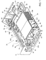
- Fig. 1 is an isometric view of a printing apparatus for printing on a block of printable pages, according to embodiments of the present invention.
- Fig. 2A is an isometric view of a printing bridge and printing device, in accordance with embodiments of the present invention.
- Fig. 2B is a side view of the printing bridge and printing device of Fig. 2A , shown as positioned above a block of pre-bound pages.
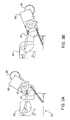
- Fig. 3A is a side view of a page-lifting assembly in a raised state, in accordance with embodiments of the present invention.
- Fig. 3B is a side view of the page-lifting assembly of Fig. 3A during lowering.
- Fig. 3C is a side view of the page-lifting assembly of Fig. 3A having been lowered onto a stack of pages.
- Fig. 4 illustrates page-lifting and flipping in accordance with embodiments of the present invention.
- Fig. 5 shows components of the printing apparatus in accordance with embodiments of the present invention, as configured in preparation for separating the stacks of a pre-bound block.
- Fig. 6 shows an isometric view of an extendible wire-holding arm and the extension mechanism, in accordance with embodiments of the present invention.
- Fig. 7 shows a side view of the wire-holding arm of Fig. 6 in an extended state.
- Fig. 8 is a cross-sectional view through the binding connection of a pre-bound block, illustrating the cutting of a binding connection, in accordance with embodiments of the present invention.
- a system for producing a book by printing directly on the pages of a pre-bound block of unprinted pages, and for separating the printed pages from the unprinted pages in the block.
- the described embodiments refer to a printing apparatus and a method for producing a book using such an apparatus.
- the printing apparatus is configured to print on the pages of a block of printable pages that are pre-bound by a flexible binding along a binding-edge of each page.
- printable pages include pages that may be printed using embodiments of the printing apparatus of the present invention. It is within the scope of the teachings herein that such pages may be pre-printed with, but not limited to, watermarks, background designs, illustrations, and pictures. Since the pages are bound together before printing, it is necessary to arrange the block in two interconnected stacks that are joined by the flexible binding.
- One or more cooperating controllers that include electronic components and programmed instructions, communicate with, and control the operation of, components of the printing apparatus.
- Such components include devices mounted on a moveable printing bridge, height-adjustable stack support tables, and devices used in separating one stack from the other.
- a moveable printing device mounted on a moveable printing bridge prints on the top surfaces of each of the stacks.
- the printing bridge also includes means for turning a printed page. Turning the page involves lifting the top page of one stack, exposing the unprinted page beneath the lifted page. The lifted page is then flipped over onto the other stack, on top of which the unprinted side of the flipped page is exposed.
- the printing bridge also includes one or more sensors for ascertaining the height of the stack below the printing device. Since the height of each of the stacks changes each time a page is turned, the printing apparatus includes two height-adjustable stack support tables. Each table supports one of the two stacks. The height-adjustable tables operate in response to the output of the height-determining sensors.
- the printing apparatus includes separation means.
- the separation means include a strong, flexible wire. Components on the moveable printing device and a wire raising and lowering device cooperate to draw the wire across the flexible binding that connects the stack of printed pages to the stack of unprinted pages. The wire cuts the binding and separates one stack from the other.
- Fig. 1 is an isometric view of a printing apparatus for printing on a block of printable pages, according to embodiments of the present invention.
- Components of printing apparatus 30 are mounted on apparatus frame 31.
- Pre-bound block 20 of printable pages is shown as placed in printing apparatus 30.
- the printable pages of block 20 are bound along a binding edge by means of a flexible binding.
- the block 20 is arranged in two stacks 20A and 20B.
- the binding edges (22A and 22B in Fig. 2B ) of stacks 20A and 20B face one another.
- Stacks 20A and 20B are joined by the flexible binding at binding connection 28. Printing is performed on printable top surfaces 26A and 26B of stacks 20A and 20B.
- Stacks 20A and 20B are supported by height-adjustable tables 32A and 32B, respectively. Up and down movement of height-adjustable tables 32A and 32B is controlled by a controller (not shown). Up and down movement of tables 32A and 32B may be actuated by, but not limited to, electric motors, pneumatic devices, hydraulic devices, or substantially any other suitable device know in the art.
- FIG. 1 A mechanism for raising or lowering height-adjustable table 32A or 32B in accordance with embodiments of the present invention is now described.
- Such a mechanism for raising and lowering table 32A is partially visible in Fig. 1 .
- a similar mechanism, not visible, is provided for raising and lowering table 32B.
- the height of table 32A is raised or lowered by means of scissor mechanism 92.
- Lower ends of one pair of legs of scissors mechanism 92 are fixed at pivot joints 100.
- the lower ends of the other two legs of scissor mechanism 92 are attached to bar 94.
- Each end of bar 94 is free to slide horizontally within a slot 96.
- One end of screw mechanism 88 is threaded into a threaded hole in bar 94.
- the other end of screw mechanism 88 is fixed.
- a motor (not shown) turns screw mechanism 88.
- screw mechanism 88 turns in one direction, the end of screw mechanism 88 is threaded deeper into bar 94, pulling bar 94 toward pivot joints 100. The effect is to bring bar 94 closer to pivot joints 100, closing scissors mechanism 92 and raising table 32A.
- Screw mechanism 88 in the reverse direction, withdraws the end of screw mechanism 88 from bar 94. Bar 94 is pushed away from pivots 100, opening scissors mechanism 92 and lowering table 32A.
- each spring 98 connects to bar 94.
- the other end of spring 98 connects to a point near pivot joint 100.
- Springs 98 assist in the raising or lowering of table 32A by providing pre-loading. Pre-loading reduces the load on the motor that turns screw mechanism 88.
- Printing bridge 42 is mounted on two slide shafts 44. (One slide shaft is shown in Fig. 1 ; both in Fig. 2A .) Friction-reducing ring 60 enables printing bridge 42 to glide back and forth along slide shaft 44.
- power unit 56 drives main belt 34. Motion of main belt 34 rotates torque shaft 36. Rotation of torque shaft 36 drives one or more timing belts 58. Timing belt 58 attaches to printing bridge 42. Driven timing belt 58 causes printing bridge 42 to slide a controlled distance along slide shaft 44. It should be understood that any other means known to one skilled in the art for effecting controlled motion of printing bridge 42 is within the scope of the teachings herein.
- Fig. 2A is an isometric view of a printing bridge and printing device, in accordance with embodiments of the present invention.
- Fig. 2B is a side view of the printing bridge and printing device of Fig. 2A , shown as positioned above a block of pre-bound pages.
- Printing device 40 is mounted on guide shaft 54 of printing bridge 42. Printing device 40 moves back and forth along guide shaft 54 in response to an applied force, as follows: In response to instructions from a controller, a motor (not shown) drives belt 52. Belt 52 is attached to printing device 40. Motion of belt 52 causes printing device 40 to move a controlled distance along guide shaft 54. In embodiments of the present invention, motion of printing device 40 along shaft 54 is perpendicular to the motion of bridge 42 along slide shafts 44.
- the combined controlled motions of printing bridge 42 along slide shafts 44 and of printing device 40 along guide shaft 54 enable the controlled positioning of printing device 40 over printable top surfaces 26A and 26B.
- Printing head 41 of printing device 40 may thus print at controlled locations on printable top surfaces 26A and 26B. It should be understood that any other means known to one skilled in the art for effecting controlled motion of printing device 40 is within the scope of the teachings herein.
- printing device 40 moves along guide shaft 54 while printing bridge 42 remains stationary at a position along slide shafts 44.
- printing head 41 may print within the boundaries of a strip of the printable surface.
- the dimensions of the strip are determined by the dimensions of the print area covered by a stationary printing head and the distance that printing head 41 travels along guide shaft 54.
- the long dimension of the strip is oriented parallel to guide shaft 54.
- Fig. 2B indicates the direction of typical motion of printing bridge 42 during a typical printing operation, in accordance with embodiments of the present invention.
- Printing device 40 is mounted on printing bridge 42 such that during a typical printing operation, printing head 41 is on the trailing edge of printing bridge 42.
- Page-lifting assembly 50 (shown in Fig. 1 and Fig. 4 ) is mounted on the leading edge of printing bridge 42, at one end of printing bridge 42.
- page-lifting assembly 50 causes roller 66 to be raised or lowered.
- page-lifting assembly 50 causes roller 66 to rotate.
- the function of roller 66 is to lift a page.
- the lifted page is raised further by page-flipping tab 62.
- a page-lifting element configured of, but not limited to, a roller, an electrostatic element, a vacuum element, or any other element known in the art that is mountable on a movable bridge and capable of at least partially lifting a page.
- Page-flipping tab 62 is mounted on the leading edge of printing bridge 42. Page-flipping tab 62 is inserted under the end of a lifted page. Page-flipping tab 62 raises the lifted page in advance of printing head 41, allowing printing head 41 to print on an unprinted surface beneath the raised page.
- Sensor lever 74 is located on page-flipping tab 62. When page-flipping tab 62 is inserted under a lifted page, the lifted page presses against sensor lever 74. Pressing against sensor lever 74 activates a sensor that sends a signal to a controller. For example, pressure lever 74 may connect to tab 75 that rotates when pressure lever 74 is pressed. Rotation of tab 75 may block a light beam. A photoelectric sensor detects the blocking of the light beam and sends a signal to a controller.
- Fig. 3A, Fig. 3B , and Fig. 3C illustrate operation of the page-lifting assembly in accordance with embodiments of the present invention.
- printing bridge 42 Prior to operating page-lifting assembly 50, printing bridge 42 is positioned near the edge of top surface 26B that is distal to binding connection 28. Page-lifting assembly 50 is mounted to one end of printing bridge 42.
- roller 66 of page-lifting assembly 50 is parked in a raised position.
- Fig. 3A is a side view of a page-lifting assembly in a raised state, in accordance with embodiments of the present invention.
- FIG. 3B is a side view of the page-lifting assembly of Fig. 3A during lowering.
- Motor 51 visible in Fig. 4
- Fig. 3C is a side view of the page-lifting assembly of Fig. 3A having been lowered onto a stack of pages.
- Roller 66 has been lowered on to top page 78 of stack 20B.
- Fig. 4 illustrates page-lifting and flipping in accordance with embodiments of the present invention.
- Roller 66 is lowered onto a corner of top page 78 of stack 20B.
- Motor 65 of roller assembly 69 begins to operate.
- operation of motor 65 causes roller 66 to rotate in the direction indicated by arrow 82.
- Roller 66 applies a friction force in the direction of arrow 82 to the corner of page 78 on which roller 66 rests.
- binding connection 28 exerts a force on top page 78 that prevents the proximal end of top page 78 from sliding. The result of the combination of the applied forces is that top page 78 bends.
- top page 78 The result of the bending of top page 78 is lifting of corner 80 of top page 78. Corner 80 is the corner of top page 78 that is distal to both roller 66 and binding connection 28. Lifting corner 80 of top page 78 partially exposes an unprinted printable upper surface 26B of stack 20B.
- top page 78 With corner 80 of top page 78 lifted, printing bridge 42 moves in the direction indicated by arrow 84. The motion of printing bridge 42 in the direction of arrow 84 inserts flipping tab 62, mounted on the leading edge of printing bridge 42, under lifted corner 80 of top page 78. Printing bridge 42 continues to move in the direction of arrow 84.
- flipping tab 62 comes into contact with top page 78, top page 78 presses on sensor lever 74.
- Top page 78 pressing on sensor lever 74 causes a signal to be sent to a controller.
- the signal due to top page 78 pressing on sensor lever 74 indicates that a sufficient portion of flipping tab 62 has been inserted under corner 80 of top page 78.
- flipping tab 62 is capable of holding top page 78 above newly-exposed unprinted printable top surface 26B.
- page-height sensors 68 are located on the underside of printing bridge 42, near the leading edge of printing bridge 42.
- page-height sensors 68 include two separate, substantially identical, mechanical elements. Each mechanical element is in the form of a lever with a wheel mounted at its end. The wheel allows the lever to glide over a page surface without disturbing the page surface. The lever is pushed upward by contact with a surface below it. The distance through which the lever is pushed upward depends on the proximity of the surface below it.
- the sensor may include one or more mechanical, electromagnetic, optical, or sonic sensors, or any other type of sensor capable of detecting the proximity of a page surface without disturbing the page.
- each mechanical element of each page-height sensor 68 includes a lever. When the lever is pushed upward through a predetermined distance, that page-height sensor is activated and sends a signal to the controller.
- the predetermined distances for activating each of the two page-height sensors differ from one another. The predetermined distances are selected such that when the distance to the surface below falls within a pre-determined acceptable range, one of page-height sensors 68 is activated, while the other is not. Activation of both sensors would indicate that the distance to the surface below is smaller than the acceptable range. A distance smaller than the acceptable range would indicate that the surface below is too high, and that the surface must be lowered. Activation of neither sensor would indicate that the distance to the surface below is greater than the acceptable range. A distance greater than the acceptable range would indicate that the surface below is too low, and that the surface must be raised.
- paper-smoothing fins 70 may be mounted on the underside of printing bridge 42 (visible in Fig. 2B and in Fig. 5 ). Paper-smoothing fins 70 rest on the surface of a page over which printing bridge 42 passes. Paper-smoothing fins 70 apply slight pressure to the page surface that is below printing bridge 42. The ends of paper-smoothing fins 70 that contact the page surface may be fitted with smooth elements. The smooth elements enable paper-smoothing fins 70 to glide over the page surface and apply downward pressure, without dragging the page sideways. When printing bridge 42 moves over a page surface during a printing operation, paper-smoothing fins 70 precede printing head 41 by a short distance. A function of paper-smoothing fins 70 is to assist in preparing an even printable surface to be printed upon by printing head 41.
- Fig. 5 shows components of the printing apparatus in accordance with embodiments of the present invention, as configured in preparation for separating the stacks of a pre-bound block.
- Printing bridge 42 is positioned near the edge of top surface 26A that is distal to binding connection 28, having completed printing on top surfaces 26B and 26A.
- the trailing end of printing device 40 faces binding connection 28. Separation is effected by means of a cutting element.
- the cutting element is strong, flexible wire 114.
- cutting means may include, but are not limited to: flexible thread, string, or wire; knives, blades, or other edges; thermal means such as resistive electric wire, concentrated radiation, or lasers; chemical means; or any other means that may be used to cut a flexible binding.
- Wire 114 extends from a bottom connection point (not shown) near the bottom of printing apparatus 30 to extendible arm 110.
- Extendible arm 110 may be raised or lowered by arm extension device 112.
- arm extension device 112. In general, and in particular during a printing operation, extendible arm 110 is in its lowered state, folded inside arm extension device 112. When extendible arm 110 is folded, wire 114 is situated near the bottom of printing apparatus 30.
- wire 114 does not interfere with the operation of other components of printing apparatus 30. In particular, wire 114 does not impede the motion of printing bridge 42, the motion of printing device 40, or the motion of height-adjustable tables 32A and 32B.
- Fig. 6 shows an isometric view of an extendible wire-holding arm and the extension mechanism, in accordance with embodiments of the present invention.
- arm extension device 112 Prior to separation of the stacks, arm extension device 112 extends extendible arm 110 to a raised position as follows: Motor 122 rotates wheel 115 in a clockwise direction. Clockwise rotation of wheel 115 pulls downward and leftward on transmission arm 109. Transmission arm 109 pulls downward on one end of extendible arm 110 at joint 113. Pulling downward on joint 113 causes extends extendible arm 110 to rotate clockwise about axis 111. Clockwise rotation of extendible arm 110 raises extendible arm 110 to an extended state.
- Fig. 7 shows a side view of the wire-holding arm of Fig. 6 in an extended state.
- Extending arm 110 causes wire 114 to extend from a bottom connection point (not shown) near the bottom of printing apparatus 30, to a connection point near the top of arm 110.
- the height of the connection point near the top of arm 110 is greater than the height of binding connection 28.
- a portion of wire 114 is in contact with the end of binding connection 28 closest to arm 110 (contact point not shown). Most of the remainder of wire 114 lies directly below binding connection 28 (not shown).
- indentation 118 on arm 110 aligns with pin 116 on printing device 40.
- Indention 118 is of such shape and size as to accommodate pin 116. Therefore, controlled movement of printing device 40 and printing bridge 42 may insert pin 116 into indentation 118.
- pin 116 When pin 116 is inserted into indentation 118, movement of pin 116 toward the left (as viewed in Fig. 7 ) causes pin 116 to pull wire 114, lifting wire 114 upward and leftward.
- binding connection 28 (not shown) resists the upward and leftward lifting of wire 114 by the motion of pin 116.
- the upward and leftward lifting of wire 114 against binding connection 28 causes wire 114 to sever binding connection 28.
- Fig. 8 is a cross-sectional view through the binding connection of a pre-bound block, illustrating the cutting of a binding connection, in accordance with embodiments of the present invention.
- Printing device 40 and pin 116 move in the direction of the arrow.
- Wire 114 contacts binding separation 28 at contact point 120.
- Motion of pin 116 in the direction of the arrow causes wire 114 to apply a force to binding separation 28 at contact point 120.
- the force applied by wire 114 to binding connection 28 at contact point 120 severs binding connection 28 at contact point 120.
- Continued motion of pin 116 in the direction of the arrow causes contact point 120 to move in the direction of the arrow along the entire length of binding connection 28.
- Fig. 8 is a cross-sectional view through the binding connection of a pre-bound block, illustrating the cutting of a binding connection, in accordance with embodiments of the present invention.
- Printing device 40 and pin 116 move in the direction of the arrow.
- Wire 114 contacts binding separation 28 at contact
- binding connection 28 to the right of contact point 120 has been severed, while binding connection 28 to the left of contact point 120 remains intact.
- the motion of pin 116 in the direction of the arrow causes wire 114 to sever binding connection 28 along its entire length.
- printing device 40 in the direction of the arrow brings printing device 40 to a position near the end of printing bridge 42 furthest from arm 110.
- printing bridge 42 may be moved in a direction away from severed binding connection 28.
- This motion of printing bridge 42 removes pin 116 so that pin 116 no longer lifts wire 114.
- extension device 112 lowers extendible arm 110 to its retracted state. Retracting extendible arm 110 again causes the entire length of wire 114 to be situated near the bottom of the printing apparatus.
- Severing binding connection 28 along its entire length separates the two stacks that make up block 20 into two separate blocks of bound pages.
- One of the two separate blocks consists entirely of printed pages, while the other block consists entirely of unprinted pages.
- the block of printed pages may then be removed from the printing apparatus.
- Printing of a book in accordance with embodiments of printing apparatus 30 is now explained with reference to Fig. 1 . Actions performed during operation of printing apparatus 30 are performed in response to instructions sent to various components of printing apparatus 30 by one or more controllers (not shown).
- Block 20 of printable pages is shown as placed in printing apparatus 30.
- Block 20 is pre-bound by a flexible binding 22 (indicated in Fig. 2B ).
- a flexible binding 22 indicated in Fig. 2B .
- all pages of block 20 are arranged in a single stack 20B.
- block 20 is arranged in two stacks 20A and 20B.
- Stacks 20A and 20B rest on height-adjustable tables 32A and 32B, respectively.
- Printing is performed on printable top surfaces 26A and 26B, of stacks 20A and 20B, respectively.
- the heights of tables 32A and 32B are adjusted so that surfaces 26A and 26B are substantially coplanar. Top surfaces 26A and 26B are joined at binding connection 28.
- printing may be performed on printable top surface 26B of single stack 20B only.
- the page turning operation described below may be performed already on the first sheet, immediately creating two stacks 20A and 20B with printable top surfaces 26A and 26B. Beginning the printing operation with turning a page would leave the first page blank. Such a page may be left intentionally blank if, for example, it were to serve as an end paper.
- printing bridge 42 and printing device 40 move sequentially to position printing head 41 above various locations of printable top surfaces 26A and 26B.
- Printing head 41 (indicated in Fig. 2B ) may print on the various locations of surfaces 26A and 26B above which it is positioned.
- the general direction of the motion of printing bridge 42 is in the direction indicated by the arrow in Fig. 2B .
- the result of the indicated motion is that printing head 41 prints on printable top surface 26B prior to printing on printable top surface 26A. Therefore, when starting to print on top surface 26B, printing bridge 42 is located at a starting position near the edge of top surface 26B that is distal to binding connection 28. During printing, the direction of motion of bridge 42 is toward the far edge of top surface 26A, the edge that is distal to binding connection 28. When printing on top surface 26A is complete, printing bridge 42 is located near the distal edge of surface 26A. Prior to returning printing bridge to its starting position, tables 32A and 32B are both lowered through a short, pre-determined distance.
- Printing bridge 42 is then returned to its starting position near the distal edge of top surface 26B.
- the purpose of lowering tables 32A and 32B prior to the return motion of printing bridge 42 to its starting position is to prevent the return motion of printing bridge 42 from disturbing top surfaces 26A and 26B.
- tables 32A and 32B are raised by the pre-determined distance through which they had been previously lowered. Tables 32A and 32B are thus returned to their previous heights. At this point, printing bridge 42 and printing device 40 are in position to print on another pair of printable top surfaces.
- New unprinted surfaces Prior to resuming printing on top surfaces 26B and 26A, new unprinted surfaces must be exposed. New unprinted surfaces are exposed by lifting the top page of stack 20B by means of page-lifting assembly 50. Lifting the top page of stack 20B exposes an unprinted printable top surface 26B. The lifted page is then flipped by means of flipping tab 62 on to the top of stack 20A, exposing the unprinted side of the flipped page. The unprinted side of the flipped forms a printable top surface 26A of stack 20A.
- printing bridge 42 continues to cause flipping tab 62 to raise top page 78.
- printing device 40 (shown in Fig. 1 ) moves back and forth along printing bridge 42, allowing printing head 41 (shown in Fig. 1 ) to print on printable top surface 26B.
- Flipping tab 62 eventually raises page 78 a sufficient amount that page 78 flips about its edge that is connected to binding connection 28 and onto stack 20A.
- Flipping page 78 onto stack 20A exposes the unprinted side of page 78.
- the unprinted side of page 78 resting atop stack 20A forms a new printable top surface 26A of stack 20A.
- Quality of printing may be adversely affected when the distance between printing head 41 and printable top surface 26B or 26A is larger or smaller than an acceptable range.
- the height of printing head 41 relative to the remainder of printing apparatus 30 is fixed. Therefore, the distance between printing head 41 and printable top surface 26B or 26A is determined by the height of printable top surface 26B or 26A.
- the distance between printable top surface 26A or 26B and printing head 41 is determined by page-height sensors 68 on the underside of printing bridge 42.
- Redeploying a top page from stack 20B to stack 20A lowers the height of top surface 26B of stack 20B, and raises the height of top surface 26A of stack 20A.
- the change in height of each top surface is equal to the thickness of a single page.
- the range of acceptable distances between printing head 41 and printable top surface 26B or 26A may be larger than the thickness of a single page.
- the heights of top surfaces 26B and 26A may remain within the acceptable range of surface heights.
- printing may proceed without any adjustment to the heights of top surfaces 26B and 26A.
- page-height sensors 68 indicate that the distance between printing head 41 and printable top surface 26B or 26A is greater than or less than the acceptable range.
- height-adjustable tables 32B and 32A adjust the heights of stacks 20B and 20A respectively, in order to bring the heights of printable top surfaces 26B and 26A to within the acceptable range.
- the signals output by page-height sensors 68 are read by a controller at two points during the motion of bridge 42 across printable top surfaces 26B and 26A. One point occurs when bridge 42 is located near the end of top surface 26B that is distal to binding connection 28, prior to the commencement of printing on printable top surface 26B. At this point, page-height sensors 68 are read in order to indicate the distance between printing head 41 and printable top surface 26B of stack 20B. At this point, should page-height sensors 68 indicate that the distance between printing head 41 and printable top surface 26B is greater than the acceptable range, height-adjustable table 32B raises stack 20B through a pre-determined distance.
- the pre-determined distance is so determined as to raise the height of top surface 26B to within the acceptable range of heights for printable top surface 26B.
- table 32A lowers stack 20A through the same pre-determined distance.
- the motion of printing bridge 42 in the general direction toward top surface 26A then continues.
- printing device 40 moves back and forth along the length of printing bridge 42.
- the motion of printing device 40 along printing bridge 42 is perpendicular to the direction of the motion of printing bridge 42.
- the combined motion of printing bridge 42 and printing device 40 may position printing head 41 over any point on printable top surface 26B. Therefore, printing head 41 may print as needed on printable top surface 26B.
- page-height sensors 68 are read at a second point during the motion of printing bridge 42 over printable top surfaces 26B and 26A. This second point occurs when the leading edge of printing bridge 42 crosses binding connection 28 and page-height sensors contact top surface 26A. At this point, page-height sensors 68 are read in order to indicate the distance between printing head 41 and printable top surface 26A of stack 20A. A page may have been redeployed from stack 20B to stack 20A, increasing the height of top surface 26A. At this point, should page-height sensors 68 indicate that the distance between printing head 41 and printable top surface 26A is smaller than the acceptable range, height-adjustable table 32A lowers stack 20A through a pre-determined distance.
- the pre-determined distance is so determined as to lower the height of top surface 26A to within the acceptable range of heights for printable top surface 26A.
- table 32B raises stack 20B through the same pre-determined distance. Movement of printing bridge 42 and printing device 40 over printable top surface 26A then continues. During the course of the motion of printing bridge 42 and printing device 40, printing head 41 may print on printable top surface 26A.
- stack 20A consists entirely of printed bound pages
- stack 20B consists entirely of unprinted bound pages.
- Printing bridge 42 is positioned above tope surface 26A, near the edge of top surface 26A that is distal to binding connection 28.
- Arm extension device 112 extends arm 110 to its raised state. When raised, extendible arm 110 holds an end of wire 114 at a height above the height of binding connection 28. The remainder of wire 114 lies below binding connection 28.
- Printing device 40 is positioned along printing bridge 42 such that pin 116 aligns with indentation 118 on extendible arm 110. With pin 116 aligned with indentation 118, printing bridge 42 moves pin 116 toward extendible arm 110. Motion of printing bridge 42 toward extendible arm 110 continues until pin 116 is inserted into indention 118.
- printing device 40 moves along printing bridge 42, conveying pin 116 away from extendible arm 110. Conveying pin 116 away from arm 110 causes pin 116 to pull wire 114 upward and against binding connection 28. Continued motion of pin 116 away from arm 110 and pulling on wire 114 causes wire 114 to sever binding connection 28. Continued motion of printing device 40 toward the end of printing bridge 42 that is distal to arm 110 completely severs binding connection 28. Severing binding connection 28 separates stack 20A of printed pages from stack 20B of unprinted pages. After separation of stack 20A from stack 20B, bridge 42 moves away from wire 114 until pin 116 disengages from wire 114. Extension device 112 retracts extendible arm 110 to its folded state. Retracting extendible arm 110 causes the entire length of wire 114 to be situated near the bottom of printing apparatus 30. Situating wire 114 near the bottom of printing apparatus 30 prevents wire 114 from interfering with the motion of moving components during any further operation of printing apparatus 30.
- printed stack 20A After printed stack 20A is separated from unprinted stack 20B, printed stack 20A may be removed from printing apparatus 30.
Landscapes
- Folding Of Thin Sheet-Like Materials, Special Discharging Devices, And Others (AREA)
- Pile Receivers (AREA)
- Financial Or Insurance-Related Operations Such As Payment And Settlement (AREA)
- Handling Of Cut Paper (AREA)
Applications Claiming Priority (1)
| Application Number | Priority Date | Filing Date | Title |
|---|---|---|---|
| IL195825A IL195825A (en) | 2008-12-09 | 2008-12-09 | System for printing a book on pre-bound pages |
Publications (2)
| Publication Number | Publication Date |
|---|---|
| EP2196319A1 true EP2196319A1 (fr) | 2010-06-16 |
| EP2196319B1 EP2196319B1 (fr) | 2011-11-09 |
Family
ID=41785663
Family Applications (1)
| Application Number | Title | Priority Date | Filing Date |
|---|---|---|---|
| EP09251767A Not-in-force EP2196319B1 (fr) | 2008-12-09 | 2009-07-09 | Système pour imprimer un livre sur des pages pré-reliées |
Country Status (6)
| Country | Link |
|---|---|
| EP (1) | EP2196319B1 (fr) |
| JP (1) | JP2010137544A (fr) |
| AT (1) | ATE532641T1 (fr) |
| AU (1) | AU2009225357A1 (fr) |
| CA (1) | CA2675824A1 (fr) |
| IL (1) | IL195825A (fr) |
Cited By (4)
| Publication number | Priority date | Publication date | Assignee | Title |
|---|---|---|---|---|
| CN103009799A (zh) * | 2012-12-28 | 2013-04-03 | 中国电子科技集团公司第四十五研究所 | 同一平面的x、y、θ方向自动对准调节装置 |
| CN104647907A (zh) * | 2015-02-15 | 2015-05-27 | 王铁苗 | 板件打标生产线及其使用方法 |
| CN114801515A (zh) * | 2022-03-17 | 2022-07-29 | 淮安阿桐自动化技术有限公司 | 一种本式证件自动翻页打印制证机 |
| AT526431A4 (de) * | 2023-01-31 | 2024-03-15 | Elke Steiner | Drucker-Anordnung sowie ein Verfahren zum Bedrucken eines vorgebundenen Buches in einer derartigen Drucker-Anordnung |
Citations (10)
| Publication number | Priority date | Publication date | Assignee | Title |
|---|---|---|---|---|
| US4029193A (en) | 1975-03-31 | 1977-06-14 | Bunker Ramo Corporation | Printer having a platen with resilient segments |
| US4776711A (en) | 1985-06-28 | 1988-10-11 | Hitachi, Ltd. | Booklet printer |
| EP0503476A1 (fr) * | 1991-03-11 | 1992-09-16 | Hitachi, Ltd. | Dispositif pour tourner les pages dans une imprimante pour livret |
| JPH05162485A (ja) | 1991-12-14 | 1993-06-29 | Ricoh Co Ltd | 画像形成装置 |
| US5267799A (en) | 1989-11-24 | 1993-12-07 | Kabushiki Kaisha Toshiba | Apparatus and method of printing data in a book, a notebook, or the like |
| US5806991A (en) | 1995-10-10 | 1998-09-15 | Huebler; Torsten | Method and printing apparatus for printing the front and/or back of individual sheets of a product in book or booklet form |
| US6036381A (en) | 1996-04-25 | 2000-03-14 | International Manufacturing & Engineering Service Company | Book printer including support for accommodating bound portion |
| US20010022911A1 (en) | 2000-03-16 | 2001-09-20 | International Business Machines Corporation | Page-turning device, and printer using same |
| US6762356B2 (en) | 2002-07-26 | 2004-07-13 | Pitney Bowes Inc. | System for turning pages of a material |
| WO2006123338A2 (fr) | 2005-05-18 | 2006-11-23 | Revoprint Ltd. | Systeme d'impression de livre et ensemble faisant appel a un bloc de pages pre-reliees |
Family Cites Families (4)
| Publication number | Priority date | Publication date | Assignee | Title |
|---|---|---|---|---|
| JPS62123949U (fr) * | 1986-01-31 | 1987-08-06 | ||
| JPH07128937A (ja) * | 1993-11-05 | 1995-05-19 | Ricoh Co Ltd | 原稿読み取り装置 |
| JP2828624B2 (ja) * | 1996-05-17 | 1998-11-25 | 日本ビジネスコンピューター株式会社 | ワイヤ・ドット・プリンタ |
| JP2002052864A (ja) * | 2000-08-09 | 2002-02-19 | Nec Kofu Ltd | 冊子のページめくり機構とページめくり方法 |
-
2008
- 2008-12-09 IL IL195825A patent/IL195825A/en active IP Right Grant
-
2009
- 2009-07-09 AT AT09251767T patent/ATE532641T1/de active
- 2009-07-09 EP EP09251767A patent/EP2196319B1/fr not_active Not-in-force
- 2009-08-04 JP JP2009181296A patent/JP2010137544A/ja active Pending
- 2009-08-17 CA CA2675824A patent/CA2675824A1/fr not_active Abandoned
- 2009-10-15 AU AU2009225357A patent/AU2009225357A1/en not_active Abandoned
Patent Citations (10)
| Publication number | Priority date | Publication date | Assignee | Title |
|---|---|---|---|---|
| US4029193A (en) | 1975-03-31 | 1977-06-14 | Bunker Ramo Corporation | Printer having a platen with resilient segments |
| US4776711A (en) | 1985-06-28 | 1988-10-11 | Hitachi, Ltd. | Booklet printer |
| US5267799A (en) | 1989-11-24 | 1993-12-07 | Kabushiki Kaisha Toshiba | Apparatus and method of printing data in a book, a notebook, or the like |
| EP0503476A1 (fr) * | 1991-03-11 | 1992-09-16 | Hitachi, Ltd. | Dispositif pour tourner les pages dans une imprimante pour livret |
| JPH05162485A (ja) | 1991-12-14 | 1993-06-29 | Ricoh Co Ltd | 画像形成装置 |
| US5806991A (en) | 1995-10-10 | 1998-09-15 | Huebler; Torsten | Method and printing apparatus for printing the front and/or back of individual sheets of a product in book or booklet form |
| US6036381A (en) | 1996-04-25 | 2000-03-14 | International Manufacturing & Engineering Service Company | Book printer including support for accommodating bound portion |
| US20010022911A1 (en) | 2000-03-16 | 2001-09-20 | International Business Machines Corporation | Page-turning device, and printer using same |
| US6762356B2 (en) | 2002-07-26 | 2004-07-13 | Pitney Bowes Inc. | System for turning pages of a material |
| WO2006123338A2 (fr) | 2005-05-18 | 2006-11-23 | Revoprint Ltd. | Systeme d'impression de livre et ensemble faisant appel a un bloc de pages pre-reliees |
Cited By (8)
| Publication number | Priority date | Publication date | Assignee | Title |
|---|---|---|---|---|
| CN103009799A (zh) * | 2012-12-28 | 2013-04-03 | 中国电子科技集团公司第四十五研究所 | 同一平面的x、y、θ方向自动对准调节装置 |
| CN103009799B (zh) * | 2012-12-28 | 2016-03-02 | 中国电子科技集团公司第四十五研究所 | 同一平面的x、y、θ方向自动对准调节装置 |
| CN104647907A (zh) * | 2015-02-15 | 2015-05-27 | 王铁苗 | 板件打标生产线及其使用方法 |
| CN104647907B (zh) * | 2015-02-15 | 2016-02-24 | 王铁苗 | 板件打标生产线及其使用方法 |
| CN114801515A (zh) * | 2022-03-17 | 2022-07-29 | 淮安阿桐自动化技术有限公司 | 一种本式证件自动翻页打印制证机 |
| AT526431A4 (de) * | 2023-01-31 | 2024-03-15 | Elke Steiner | Drucker-Anordnung sowie ein Verfahren zum Bedrucken eines vorgebundenen Buches in einer derartigen Drucker-Anordnung |
| AT526431B1 (de) * | 2023-01-31 | 2024-03-15 | Elke Steiner | Drucker-Anordnung sowie ein Verfahren zum Bedrucken eines vorgebundenen Buches in einer derartigen Drucker-Anordnung |
| WO2024159254A1 (fr) * | 2023-01-31 | 2024-08-08 | Steiner Elke | Ensemble imprimante et procédé pour imprimer un livre pré-lié dans un tel ensemble imprimante |
Also Published As
| Publication number | Publication date |
|---|---|
| IL195825A0 (en) | 2009-09-01 |
| IL195825A (en) | 2012-03-29 |
| JP2010137544A (ja) | 2010-06-24 |
| AU2009225357A1 (en) | 2010-06-24 |
| ATE532641T1 (de) | 2011-11-15 |
| EP2196319B1 (fr) | 2011-11-09 |
| CA2675824A1 (fr) | 2010-06-08 |
Similar Documents
| Publication | Publication Date | Title |
|---|---|---|
| US6708967B1 (en) | Method and apparatus for making booklets | |
| EP2196319B1 (fr) | Système pour imprimer un livre sur des pages pré-reliées | |
| US8231286B2 (en) | System for printing a book on pre-bound pages | |
| JP4192083B2 (ja) | プリンタ | |
| KR101667819B1 (ko) | 압력 감소 폴딩 시스템 | |
| US8388245B2 (en) | Incorporated printer with separate-sheet printing and book printing capabilities | |
| EP4450441A1 (fr) | Dispositif de rainage de papier et imprimante | |
| KR20050083015A (ko) | 매체 반송 기구, 매체 반송 장치 및 매체 반송 방법 | |
| US7197971B2 (en) | Device for trimming sheet material | |
| US12617649B2 (en) | Paper creasing device and printer | |
| JP7724950B2 (ja) | 用紙の筋入れ装置及びプリンタ | |
| JP2882499B2 (ja) | プリンタ | |
| JP3022265B2 (ja) | プリンタの紙送り構造 | |
| JPS5991076A (ja) | プリンタ装置 | |
| JP3718757B2 (ja) | 冊子状媒体の自動改頁装置 | |
| JP3295063B2 (ja) | プリンタの紙送り構造 | |
| JP5560884B2 (ja) | プリンタ | |
| JPH03208691A (ja) | 頁めくり装置 | |
| JP4784331B2 (ja) | 自動改頁機構 | |
| JP2000118078A (ja) | プリンタのギャップ調整装置 | |
| JPH0485089A (ja) | 紙葉めくり装置 | |
| JPH04246038A (ja) | 給紙装置 | |
| JP2003165252A (ja) | プリンタ |
Legal Events
| Date | Code | Title | Description |
|---|---|---|---|
| PUAI | Public reference made under article 153(3) epc to a published international application that has entered the european phase |
Free format text: ORIGINAL CODE: 0009012 |
|
| AK | Designated contracting states |
Kind code of ref document: A1 Designated state(s): AT BE BG CH CY CZ DE DK EE ES FI FR GB GR HR HU IE IS IT LI LT LU LV MC MK MT NL NO PL PT RO SE SI SK SM TR |
|
| AX | Request for extension of the european patent |
Extension state: AL BA RS |
|
| 17P | Request for examination filed |
Effective date: 20101210 |
|
| GRAP | Despatch of communication of intention to grant a patent |
Free format text: ORIGINAL CODE: EPIDOSNIGR1 |
|
| RIC1 | Information provided on ipc code assigned before grant |
Ipc: B41J 11/20 20060101ALI20110531BHEP Ipc: B41J 3/28 20060101AFI20110531BHEP |
|
| GRAS | Grant fee paid |
Free format text: ORIGINAL CODE: EPIDOSNIGR3 |
|
| GRAA | (expected) grant |
Free format text: ORIGINAL CODE: 0009210 |
|
| AK | Designated contracting states |
Kind code of ref document: B1 Designated state(s): AT BE BG CH CY CZ DE DK EE ES FI FR GB GR HR HU IE IS IT LI LT LU LV MC MK MT NL NO PL PT RO SE SI SK SM TR |
|
| REG | Reference to a national code |
Ref country code: GB Ref legal event code: FG4D |
|
| REG | Reference to a national code |
Ref country code: CH Ref legal event code: EP |
|
| REG | Reference to a national code |
Ref country code: IE Ref legal event code: FG4D |
|
| REG | Reference to a national code |
Ref country code: DE Ref legal event code: R096 Ref document number: 602009003588 Country of ref document: DE Effective date: 20120119 |
|
| REG | Reference to a national code |
Ref country code: NL Ref legal event code: VDEP Effective date: 20111109 |
|
| LTIE | Lt: invalidation of european patent or patent extension |
Effective date: 20111109 |
|
| PG25 | Lapsed in a contracting state [announced via postgrant information from national office to epo] |
Ref country code: NO Free format text: LAPSE BECAUSE OF FAILURE TO SUBMIT A TRANSLATION OF THE DESCRIPTION OR TO PAY THE FEE WITHIN THE PRESCRIBED TIME-LIMIT Effective date: 20120209 Ref country code: IS Free format text: LAPSE BECAUSE OF FAILURE TO SUBMIT A TRANSLATION OF THE DESCRIPTION OR TO PAY THE FEE WITHIN THE PRESCRIBED TIME-LIMIT Effective date: 20120309 Ref country code: LT Free format text: LAPSE BECAUSE OF FAILURE TO SUBMIT A TRANSLATION OF THE DESCRIPTION OR TO PAY THE FEE WITHIN THE PRESCRIBED TIME-LIMIT Effective date: 20111109 |
|
| PG25 | Lapsed in a contracting state [announced via postgrant information from national office to epo] |
Ref country code: HR Free format text: LAPSE BECAUSE OF FAILURE TO SUBMIT A TRANSLATION OF THE DESCRIPTION OR TO PAY THE FEE WITHIN THE PRESCRIBED TIME-LIMIT Effective date: 20111109 Ref country code: BE Free format text: LAPSE BECAUSE OF FAILURE TO SUBMIT A TRANSLATION OF THE DESCRIPTION OR TO PAY THE FEE WITHIN THE PRESCRIBED TIME-LIMIT Effective date: 20111109 Ref country code: NL Free format text: LAPSE BECAUSE OF FAILURE TO SUBMIT A TRANSLATION OF THE DESCRIPTION OR TO PAY THE FEE WITHIN THE PRESCRIBED TIME-LIMIT Effective date: 20111109 Ref country code: PL Free format text: LAPSE BECAUSE OF FAILURE TO SUBMIT A TRANSLATION OF THE DESCRIPTION OR TO PAY THE FEE WITHIN THE PRESCRIBED TIME-LIMIT Effective date: 20111109 Ref country code: PT Free format text: LAPSE BECAUSE OF FAILURE TO SUBMIT A TRANSLATION OF THE DESCRIPTION OR TO PAY THE FEE WITHIN THE PRESCRIBED TIME-LIMIT Effective date: 20120309 Ref country code: LV Free format text: LAPSE BECAUSE OF FAILURE TO SUBMIT A TRANSLATION OF THE DESCRIPTION OR TO PAY THE FEE WITHIN THE PRESCRIBED TIME-LIMIT Effective date: 20111109 Ref country code: SE Free format text: LAPSE BECAUSE OF FAILURE TO SUBMIT A TRANSLATION OF THE DESCRIPTION OR TO PAY THE FEE WITHIN THE PRESCRIBED TIME-LIMIT Effective date: 20111109 Ref country code: GR Free format text: LAPSE BECAUSE OF FAILURE TO SUBMIT A TRANSLATION OF THE DESCRIPTION OR TO PAY THE FEE WITHIN THE PRESCRIBED TIME-LIMIT Effective date: 20120210 Ref country code: SI Free format text: LAPSE BECAUSE OF FAILURE TO SUBMIT A TRANSLATION OF THE DESCRIPTION OR TO PAY THE FEE WITHIN THE PRESCRIBED TIME-LIMIT Effective date: 20111109 |
|
| PG25 | Lapsed in a contracting state [announced via postgrant information from national office to epo] |
Ref country code: CY Free format text: LAPSE BECAUSE OF FAILURE TO SUBMIT A TRANSLATION OF THE DESCRIPTION OR TO PAY THE FEE WITHIN THE PRESCRIBED TIME-LIMIT Effective date: 20111109 |
|
| PG25 | Lapsed in a contracting state [announced via postgrant information from national office to epo] |
Ref country code: DK Free format text: LAPSE BECAUSE OF FAILURE TO SUBMIT A TRANSLATION OF THE DESCRIPTION OR TO PAY THE FEE WITHIN THE PRESCRIBED TIME-LIMIT Effective date: 20111109 Ref country code: EE Free format text: LAPSE BECAUSE OF FAILURE TO SUBMIT A TRANSLATION OF THE DESCRIPTION OR TO PAY THE FEE WITHIN THE PRESCRIBED TIME-LIMIT Effective date: 20111109 Ref country code: BG Free format text: LAPSE BECAUSE OF FAILURE TO SUBMIT A TRANSLATION OF THE DESCRIPTION OR TO PAY THE FEE WITHIN THE PRESCRIBED TIME-LIMIT Effective date: 20120209 Ref country code: SK Free format text: LAPSE BECAUSE OF FAILURE TO SUBMIT A TRANSLATION OF THE DESCRIPTION OR TO PAY THE FEE WITHIN THE PRESCRIBED TIME-LIMIT Effective date: 20111109 Ref country code: CZ Free format text: LAPSE BECAUSE OF FAILURE TO SUBMIT A TRANSLATION OF THE DESCRIPTION OR TO PAY THE FEE WITHIN THE PRESCRIBED TIME-LIMIT Effective date: 20111109 |
|
| PG25 | Lapsed in a contracting state [announced via postgrant information from national office to epo] |
Ref country code: RO Free format text: LAPSE BECAUSE OF FAILURE TO SUBMIT A TRANSLATION OF THE DESCRIPTION OR TO PAY THE FEE WITHIN THE PRESCRIBED TIME-LIMIT Effective date: 20111109 Ref country code: IT Free format text: LAPSE BECAUSE OF FAILURE TO SUBMIT A TRANSLATION OF THE DESCRIPTION OR TO PAY THE FEE WITHIN THE PRESCRIBED TIME-LIMIT Effective date: 20111109 |
|
| PLBE | No opposition filed within time limit |
Free format text: ORIGINAL CODE: 0009261 |
|
| STAA | Information on the status of an ep patent application or granted ep patent |
Free format text: STATUS: NO OPPOSITION FILED WITHIN TIME LIMIT |
|
| REG | Reference to a national code |
Ref country code: AT Ref legal event code: MK05 Ref document number: 532641 Country of ref document: AT Kind code of ref document: T Effective date: 20111109 |
|
| 26N | No opposition filed |
Effective date: 20120810 |
|
| REG | Reference to a national code |
Ref country code: DE Ref legal event code: R097 Ref document number: 602009003588 Country of ref document: DE Effective date: 20120810 |
|
| PG25 | Lapsed in a contracting state [announced via postgrant information from national office to epo] |
Ref country code: AT Free format text: LAPSE BECAUSE OF FAILURE TO SUBMIT A TRANSLATION OF THE DESCRIPTION OR TO PAY THE FEE WITHIN THE PRESCRIBED TIME-LIMIT Effective date: 20111109 |
|
| PG25 | Lapsed in a contracting state [announced via postgrant information from national office to epo] |
Ref country code: MK Free format text: LAPSE BECAUSE OF FAILURE TO SUBMIT A TRANSLATION OF THE DESCRIPTION OR TO PAY THE FEE WITHIN THE PRESCRIBED TIME-LIMIT Effective date: 20111109 Ref country code: MC Free format text: LAPSE BECAUSE OF NON-PAYMENT OF DUE FEES Effective date: 20120731 |
|
| PG25 | Lapsed in a contracting state [announced via postgrant information from national office to epo] |
Ref country code: ES Free format text: LAPSE BECAUSE OF FAILURE TO SUBMIT A TRANSLATION OF THE DESCRIPTION OR TO PAY THE FEE WITHIN THE PRESCRIBED TIME-LIMIT Effective date: 20120220 |
|
| REG | Reference to a national code |
Ref country code: IE Ref legal event code: MM4A |
|
| PG25 | Lapsed in a contracting state [announced via postgrant information from national office to epo] |
Ref country code: FI Free format text: LAPSE BECAUSE OF FAILURE TO SUBMIT A TRANSLATION OF THE DESCRIPTION OR TO PAY THE FEE WITHIN THE PRESCRIBED TIME-LIMIT Effective date: 20111109 |
|
| PG25 | Lapsed in a contracting state [announced via postgrant information from national office to epo] |
Ref country code: IE Free format text: LAPSE BECAUSE OF NON-PAYMENT OF DUE FEES Effective date: 20120709 Ref country code: MT Free format text: LAPSE BECAUSE OF FAILURE TO SUBMIT A TRANSLATION OF THE DESCRIPTION OR TO PAY THE FEE WITHIN THE PRESCRIBED TIME-LIMIT Effective date: 20111109 |
|
| REG | Reference to a national code |
Ref country code: CH Ref legal event code: PL |
|
| PG25 | Lapsed in a contracting state [announced via postgrant information from national office to epo] |
Ref country code: TR Free format text: LAPSE BECAUSE OF FAILURE TO SUBMIT A TRANSLATION OF THE DESCRIPTION OR TO PAY THE FEE WITHIN THE PRESCRIBED TIME-LIMIT Effective date: 20111109 Ref country code: CH Free format text: LAPSE BECAUSE OF NON-PAYMENT OF DUE FEES Effective date: 20130731 Ref country code: LI Free format text: LAPSE BECAUSE OF NON-PAYMENT OF DUE FEES Effective date: 20130731 |
|
| PG25 | Lapsed in a contracting state [announced via postgrant information from national office to epo] |
Ref country code: LU Free format text: LAPSE BECAUSE OF NON-PAYMENT OF DUE FEES Effective date: 20120709 Ref country code: SM Free format text: LAPSE BECAUSE OF FAILURE TO SUBMIT A TRANSLATION OF THE DESCRIPTION OR TO PAY THE FEE WITHIN THE PRESCRIBED TIME-LIMIT Effective date: 20111109 |
|
| PG25 | Lapsed in a contracting state [announced via postgrant information from national office to epo] |
Ref country code: HU Free format text: LAPSE BECAUSE OF FAILURE TO SUBMIT A TRANSLATION OF THE DESCRIPTION OR TO PAY THE FEE WITHIN THE PRESCRIBED TIME-LIMIT Effective date: 20090709 |
|
| REG | Reference to a national code |
Ref country code: FR Ref legal event code: PLFP Year of fee payment: 8 |
|
| PGFP | Annual fee paid to national office [announced via postgrant information from national office to epo] |
Ref country code: DE Payment date: 20160722 Year of fee payment: 8 Ref country code: GB Payment date: 20160721 Year of fee payment: 8 |
|
| PGFP | Annual fee paid to national office [announced via postgrant information from national office to epo] |
Ref country code: FR Payment date: 20160721 Year of fee payment: 8 |
|
| REG | Reference to a national code |
Ref country code: DE Ref legal event code: R119 Ref document number: 602009003588 Country of ref document: DE |
|
| GBPC | Gb: european patent ceased through non-payment of renewal fee |
Effective date: 20170709 |
|
| REG | Reference to a national code |
Ref country code: FR Ref legal event code: ST Effective date: 20180330 |
|
| PG25 | Lapsed in a contracting state [announced via postgrant information from national office to epo] |
Ref country code: GB Free format text: LAPSE BECAUSE OF NON-PAYMENT OF DUE FEES Effective date: 20170709 Ref country code: DE Free format text: LAPSE BECAUSE OF NON-PAYMENT OF DUE FEES Effective date: 20180201 |
|
| PG25 | Lapsed in a contracting state [announced via postgrant information from national office to epo] |
Ref country code: FR Free format text: LAPSE BECAUSE OF NON-PAYMENT OF DUE FEES Effective date: 20170731 |