EP2196441B1 - Beschleunigte Alterung von phosphordotierten optischen Fasern - Google Patents
Beschleunigte Alterung von phosphordotierten optischen Fasern Download PDFInfo
- Publication number
- EP2196441B1 EP2196441B1 EP10157306.1A EP10157306A EP2196441B1 EP 2196441 B1 EP2196441 B1 EP 2196441B1 EP 10157306 A EP10157306 A EP 10157306A EP 2196441 B1 EP2196441 B1 EP 2196441B1
- Authority
- EP
- European Patent Office
- Prior art keywords
- fiber
- deuterium
- optical fiber
- passivation
- hydrogen
- Prior art date
- Legal status (The legal status is an assumption and is not a legal conclusion. Google has not performed a legal analysis and makes no representation as to the accuracy of the status listed.)
- Ceased
Links
- 239000013307 optical fiber Substances 0.000 title claims description 46
- 230000032683 aging Effects 0.000 title description 4
- 239000000835 fiber Substances 0.000 claims description 121
- YZCKVEUIGOORGS-OUBTZVSYSA-N Deuterium Chemical compound [2H] YZCKVEUIGOORGS-OUBTZVSYSA-N 0.000 claims description 48
- 229910052805 deuterium Inorganic materials 0.000 claims description 48
- 238000000034 method Methods 0.000 claims description 37
- VYPSYNLAJGMNEJ-UHFFFAOYSA-N Silicium dioxide Chemical group O=[Si]=O VYPSYNLAJGMNEJ-UHFFFAOYSA-N 0.000 claims description 22
- YBMRDBCBODYGJE-UHFFFAOYSA-N germanium dioxide Chemical compound O=[Ge]=O YBMRDBCBODYGJE-UHFFFAOYSA-N 0.000 claims description 22
- 238000011282 treatment Methods 0.000 claims description 14
- 239000000203 mixture Substances 0.000 claims description 11
- 239000000377 silicon dioxide Substances 0.000 claims description 11
- IJGRMHOSHXDMSA-UHFFFAOYSA-N Atomic nitrogen Chemical compound N#N IJGRMHOSHXDMSA-UHFFFAOYSA-N 0.000 claims description 6
- 229910052681 coesite Inorganic materials 0.000 claims description 4
- 229910052906 cristobalite Inorganic materials 0.000 claims description 4
- 239000011261 inert gas Substances 0.000 claims description 4
- 229910052682 stishovite Inorganic materials 0.000 claims description 4
- 229910052905 tridymite Inorganic materials 0.000 claims description 4
- 238000010438 heat treatment Methods 0.000 claims description 3
- 238000011221 initial treatment Methods 0.000 claims description 3
- 229910052757 nitrogen Inorganic materials 0.000 claims description 3
- 238000002161 passivation Methods 0.000 description 53
- 229910052739 hydrogen Inorganic materials 0.000 description 49
- 239000001257 hydrogen Substances 0.000 description 49
- UFHFLCQGNIYNRP-UHFFFAOYSA-N Hydrogen Chemical compound [H][H] UFHFLCQGNIYNRP-UHFFFAOYSA-N 0.000 description 42
- 230000005540 biological transmission Effects 0.000 description 23
- 230000003287 optical effect Effects 0.000 description 23
- 239000011521 glass Substances 0.000 description 22
- 230000000694 effects Effects 0.000 description 19
- 239000002019 doping agent Substances 0.000 description 18
- 230000008569 process Effects 0.000 description 16
- 230000004913 activation Effects 0.000 description 15
- 239000006185 dispersion Substances 0.000 description 15
- 229910052782 aluminium Inorganic materials 0.000 description 14
- 238000006243 chemical reaction Methods 0.000 description 14
- 229910052698 phosphorus Inorganic materials 0.000 description 13
- 230000007547 defect Effects 0.000 description 10
- 238000009826 distribution Methods 0.000 description 10
- 206010011906 Death Diseases 0.000 description 9
- XAGFODPZIPBFFR-UHFFFAOYSA-N aluminium Chemical compound [Al] XAGFODPZIPBFFR-UHFFFAOYSA-N 0.000 description 8
- OAICVXFJPJFONN-UHFFFAOYSA-N Phosphorus Chemical compound [P] OAICVXFJPJFONN-UHFFFAOYSA-N 0.000 description 7
- 230000006870 function Effects 0.000 description 7
- 229910052732 germanium Inorganic materials 0.000 description 7
- 239000011574 phosphorus Substances 0.000 description 7
- 238000009792 diffusion process Methods 0.000 description 6
- 238000011109 contamination Methods 0.000 description 5
- 238000013461 design Methods 0.000 description 5
- 230000015556 catabolic process Effects 0.000 description 4
- 238000005253 cladding Methods 0.000 description 4
- 238000006731 degradation reaction Methods 0.000 description 4
- 238000002474 experimental method Methods 0.000 description 4
- GNPVGFCGXDBREM-UHFFFAOYSA-N germanium atom Chemical compound [Ge] GNPVGFCGXDBREM-UHFFFAOYSA-N 0.000 description 4
- 150000002431 hydrogen Chemical class 0.000 description 4
- 238000009434 installation Methods 0.000 description 4
- 238000010521 absorption reaction Methods 0.000 description 3
- 238000013459 approach Methods 0.000 description 3
- 230000001934 delay Effects 0.000 description 3
- 238000005259 measurement Methods 0.000 description 3
- 238000002156 mixing Methods 0.000 description 3
- 238000004088 simulation Methods 0.000 description 3
- 238000001179 sorption measurement Methods 0.000 description 3
- 239000000126 substance Substances 0.000 description 3
- 229910052691 Erbium Inorganic materials 0.000 description 2
- 230000008901 benefit Effects 0.000 description 2
- 230000008859 change Effects 0.000 description 2
- 238000010494 dissociation reaction Methods 0.000 description 2
- 230000005593 dissociations Effects 0.000 description 2
- UYAHIZSMUZPPFV-UHFFFAOYSA-N erbium Chemical compound [Er] UYAHIZSMUZPPFV-UHFFFAOYSA-N 0.000 description 2
- 238000001914 filtration Methods 0.000 description 2
- 239000007789 gas Substances 0.000 description 2
- 230000007774 longterm Effects 0.000 description 2
- 238000004519 manufacturing process Methods 0.000 description 2
- 239000000463 material Substances 0.000 description 2
- 230000004048 modification Effects 0.000 description 2
- 238000012986 modification Methods 0.000 description 2
- 230000000737 periodic effect Effects 0.000 description 2
- 238000000623 plasma-assisted chemical vapour deposition Methods 0.000 description 2
- 230000009257 reactivity Effects 0.000 description 2
- 238000012360 testing method Methods 0.000 description 2
- 230000009466 transformation Effects 0.000 description 2
- XLYOFNOQVPJJNP-UHFFFAOYSA-N water Substances O XLYOFNOQVPJJNP-UHFFFAOYSA-N 0.000 description 2
- ZOXJGFHDIHLPTG-UHFFFAOYSA-N Boron Chemical compound [B] ZOXJGFHDIHLPTG-UHFFFAOYSA-N 0.000 description 1
- PXGOKWXKJXAPGV-UHFFFAOYSA-N Fluorine Chemical compound FF PXGOKWXKJXAPGV-UHFFFAOYSA-N 0.000 description 1
- 229910005933 Ge—P Inorganic materials 0.000 description 1
- 229910000577 Silicon-germanium Inorganic materials 0.000 description 1
- LEVVHYCKPQWKOP-UHFFFAOYSA-N [Si].[Ge] Chemical compound [Si].[Ge] LEVVHYCKPQWKOP-UHFFFAOYSA-N 0.000 description 1
- 238000000862 absorption spectrum Methods 0.000 description 1
- 230000002411 adverse Effects 0.000 description 1
- PNEYBMLMFCGWSK-UHFFFAOYSA-N aluminium oxide Inorganic materials [O-2].[O-2].[O-2].[Al+3].[Al+3] PNEYBMLMFCGWSK-UHFFFAOYSA-N 0.000 description 1
- 238000004458 analytical method Methods 0.000 description 1
- 230000003466 anti-cipated effect Effects 0.000 description 1
- 230000009286 beneficial effect Effects 0.000 description 1
- 230000015572 biosynthetic process Effects 0.000 description 1
- 229910052796 boron Inorganic materials 0.000 description 1
- 238000004364 calculation method Methods 0.000 description 1
- 238000006555 catalytic reaction Methods 0.000 description 1
- 238000005229 chemical vapour deposition Methods 0.000 description 1
- 238000013034 coating degradation Methods 0.000 description 1
- 238000004891 communication Methods 0.000 description 1
- 230000000052 comparative effect Effects 0.000 description 1
- 238000007796 conventional method Methods 0.000 description 1
- 229910052593 corundum Inorganic materials 0.000 description 1
- 230000008878 coupling Effects 0.000 description 1
- 238000010168 coupling process Methods 0.000 description 1
- 238000005859 coupling reaction Methods 0.000 description 1
- 230000018044 dehydration Effects 0.000 description 1
- 238000006297 dehydration reaction Methods 0.000 description 1
- 230000001419 dependent effect Effects 0.000 description 1
- 238000001514 detection method Methods 0.000 description 1
- 238000011161 development Methods 0.000 description 1
- 230000018109 developmental process Effects 0.000 description 1
- -1 e.g. Substances 0.000 description 1
- 238000005516 engineering process Methods 0.000 description 1
- XVOCEVMHNRHJMX-UHFFFAOYSA-N ethyl-hydroxy-oxogermane Chemical compound CC[Ge](O)=O XVOCEVMHNRHJMX-UHFFFAOYSA-N 0.000 description 1
- 229910052731 fluorine Inorganic materials 0.000 description 1
- 239000011737 fluorine Substances 0.000 description 1
- 230000004907 flux Effects 0.000 description 1
- 239000003365 glass fiber Substances 0.000 description 1
- 125000002887 hydroxy group Chemical group [H]O* 0.000 description 1
- 230000001939 inductive effect Effects 0.000 description 1
- 230000010354 integration Effects 0.000 description 1
- 238000011835 investigation Methods 0.000 description 1
- 230000005865 ionizing radiation Effects 0.000 description 1
- 230000007246 mechanism Effects 0.000 description 1
- 238000012544 monitoring process Methods 0.000 description 1
- 238000005457 optimization Methods 0.000 description 1
- 230000008520 organization Effects 0.000 description 1
- 238000004806 packaging method and process Methods 0.000 description 1
- 229920000642 polymer Polymers 0.000 description 1
- 238000002203 pretreatment Methods 0.000 description 1
- 238000012545 processing Methods 0.000 description 1
- 238000007670 refining Methods 0.000 description 1
- 230000004044 response Effects 0.000 description 1
- 230000002441 reversible effect Effects 0.000 description 1
- 230000035945 sensitivity Effects 0.000 description 1
- 239000004071 soot Substances 0.000 description 1
- 238000001228 spectrum Methods 0.000 description 1
- 238000003860 storage Methods 0.000 description 1
- 238000007740 vapor deposition Methods 0.000 description 1
- 229910001845 yogo sapphire Inorganic materials 0.000 description 1
Images
Classifications
-
- C—CHEMISTRY; METALLURGY
- C03—GLASS; MINERAL OR SLAG WOOL
- C03C—CHEMICAL COMPOSITION OF GLASSES, GLAZES OR VITREOUS ENAMELS; SURFACE TREATMENT OF GLASS; SURFACE TREATMENT OF FIBRES OR FILAMENTS MADE FROM GLASS, MINERALS OR SLAGS; JOINING GLASS TO GLASS OR OTHER MATERIALS
- C03C13/00—Fibre or filament compositions
- C03C13/04—Fibre optics, e.g. core and clad fibre compositions
- C03C13/045—Silica-containing oxide glass compositions
- C03C13/047—Silica-containing oxide glass compositions containing deuterium
-
- C—CHEMISTRY; METALLURGY
- C03—GLASS; MINERAL OR SLAG WOOL
- C03C—CHEMICAL COMPOSITION OF GLASSES, GLAZES OR VITREOUS ENAMELS; SURFACE TREATMENT OF GLASS; SURFACE TREATMENT OF FIBRES OR FILAMENTS MADE FROM GLASS, MINERALS OR SLAGS; JOINING GLASS TO GLASS OR OTHER MATERIALS
- C03C25/00—Surface treatment of fibres or filaments made from glass, minerals or slags
- C03C25/60—Surface treatment of fibres or filaments made from glass, minerals or slags by diffusing ions or metals into the surface
- C03C25/607—Surface treatment of fibres or filaments made from glass, minerals or slags by diffusing ions or metals into the surface in the gaseous phase
-
- C—CHEMISTRY; METALLURGY
- C03—GLASS; MINERAL OR SLAG WOOL
- C03C—CHEMICAL COMPOSITION OF GLASSES, GLAZES OR VITREOUS ENAMELS; SURFACE TREATMENT OF GLASS; SURFACE TREATMENT OF FIBRES OR FILAMENTS MADE FROM GLASS, MINERALS OR SLAGS; JOINING GLASS TO GLASS OR OTHER MATERIALS
- C03C25/00—Surface treatment of fibres or filaments made from glass, minerals or slags
- C03C25/62—Surface treatment of fibres or filaments made from glass, minerals or slags by application of electric or wave energy; by particle radiation or ion implantation
- C03C25/626—Particle radiation or ion implantation
- C03C25/6286—Ion implantation
Definitions
- This invention relates to multimode fiber optimized for high capacity transmission around 850nm as well as across wider bandwidths, and optical fiber transmission systems employing that fiber. More specifically it relates to methods for determining conditions for passivation of multiply-doped optical fibers to the effects of hydrogen.
- multi-transverse-mode optical fiber (hereinafter multimode fiber) fiber has an established status for short haul applications, and specialty fibers.
- LAN Local Area Network
- multimode fiber fiber
- Such systems enable low cost by utilizing serial transmission, loose alignment tolerances between source and fiber end, and large alignment tolerances within connections and splices.
- LAN Local Area Network
- the industry has set a standard for minimum acceptable transmission distance, and minimum optical fiber performance for that distance.
- the distance in current use is 300 meters for a single in-building optical link.
- In-building optical links comprise the vast majority of optical links in use today.
- the IEEE draft protocol for 10GBASE-LX4 is a four-channel WDM system operating around 1310nm, that can support up to 300 meters on standard grade multimode fibers.
- This 10GBASE-LX4 solution has met with only modest success in the market due to high optical complexity and tight single mode tolerances, resulting in high cost.
- OM3 fibers per the International Standards Organization (ISO) 11801 designation, are fibers with an effective modal bandwidth (EMB) of 2000 MHz.km at 850 nm.
- EMB effective modal bandwidth
- the integration of VCSEL launch and OM3 fiber provides a low cost 300 meter solution for 10 Gbps LAN, or Gbps Storage Area Network (SAN), transmission, and was standardized by IEEE802.3 in 2002. Typical reach is 1.1 km with state of the art OM3 compliant fiber. Since 10GBASE-SR over OM3 fiber is the lowest cost 10 Gb/s 300 meter system, it is the preferred system for new fiber installations.
- IEEE has established the 802.3 10GBASE-LRM (Long Reach Multimode) protocol for 10 Gbps single channel transmission at 1300nm over installed-base Fiber Distributed Data Interface (FDDI) grade, OM2 grade, and OM3 grade, fibers.
- FDDI Fiber Distributed Data Interface
- OM2 grade OM2 grade
- OM3 grade fibers.
- FDDI grade, OM2, and OM3, grade fibers is optimized for 1300nm performance with laser sources.
- the 99% 10GBASE-LRM reach is demonstrated to be only 220m for FDDI grade, but an acceptable 300m for OM3 fiber using electronic dispersion compensation and an offset launch condition.
- the cost of 10GBASE-LRM is expected to be higher than 10GBASE-SR, but lower than 10GBASE-LX4 (the four channel multiplexed system), making it potentially viable in the market place for existing multimode fiber installations.
- a reasonable next-step in higher speed transmission over multimode fiber would be 40 Gbps.
- the two most likely candidates are (what would be called) 40GBASE-SX4 supporting 300 meters over OM3 fiber, and 40GBASE-LRM supporting 220 meter over FDDI grade, OM2, and OM3 fibers.
- the 40GBASE-SX4 would be a CWDM (Coarse Wavelength Division Multiplexing) solution similar to the unsuccessful 10GBASE-LX4 solution, but with some key advantages: 1) Lower cost 850 nm VCSELs would be used instead of DFB (Distributed FeedBack) lasers, 2) Lower packaging cost would be enabled by multimode tolerances 10 times easier than the singlemode tolerances required for LX-4. 3)
- the use of conventional low cost CMOS integrated circuits is enabled with an SX-4 solution operating at 10 GHz frequencies, vs the more expensive silicon-germanium materials required for the 40 GHz ICs used for serial 40 Gb/s solutions.
- the next speed of Ethernet is not 40 GbE but rather 100GbE, with at least one multimode fiber solution included.
- One solution would be 10 x 10Gb parallel transmission over multimode fiber in ribbons. This solution would be very cost effective up to 100m, but would become more expensive than CWDM solutions beyond 200m.
- multimode fibers are needed that are optimized across broad wavelength ranges, coupled with appropriate laser launch conditions, for wavelengths to at least 300 meters, and data rates at 1, 10, and 100 Gb/s.
- the objective is to design fibers that maintain the present low cost for 1 or 10Gbps at 850nm, while opening up other wavelength bands for CWDM of 10 and 20Gbps transmission.
- the improved multimode optical fibers have cores doped with aluminum and/or phosphorus. In preferred embodiments they are doped with germanium and phosphorus, or germanium and aluminum. Optical fibers with these multiply doped cores are shown to provide the optical transmission qualities necessary to meet new standards for short haul optical fiber links. More details on these multiply doped optical fibers are set forth in United States Application 2008/0050075 A1 .
- EP 0 673 895 A2 describes that glass optical waveguides subject to hydrogen-induced loss increases can be passivated by treating the glass with deuterium.
- the deuterium-treated glass not only exhibits a lower rate of loss increase when later exposed to environments containing H2, but also retains high transmission of light in the 1.55 and 1.31 micrometer wavelength regions immediately after the deuterium heat treatment.
- the method applies to Er-doped fiber, transmission fiber and planar waveguides. Under some circumstances, hydrogen can be substituted for deuterium.
- passivation with deuterium often increases the initial attenuation of the fiber and for some fiber types or certain regimes of passivation, the resulting fiber can have significantly higher attenuation at end of life than an untreated fiber. Loss caused by both passivation and hydrogen exposure during life varies greatly depending on glass composition, so commercially important fiber types, like singlemode fiber, erbium doped fiber and multimode fiber, all behave differently. Optimum passivation conditions exist, but because the theory of defect passivation is not well understood, choice of passivation conditions has not been well-founded.
- Modified Chemical Vapor Deposition MCVD
- Plasma enhanced Chemical Vapor Deposition PCVD
- OTD Outside Vapor Deposition
- Deviations in the profile near the core-clad boundary are also common in the OVD process where diffusion of dopants occurs readily in soot bodies during dehydration.
- Overfill bandwidth is of limited use for characterizing fibers for laser launch applications. Values of (Max- Min) centroid delays or mask widths derived from differential mode delay (DMD) measurements are more appropriate. DMD 0-23 micron mask width values ⁇ 0.33 ps/nm are preferred for 10Gbps transmission over 300m with VCSELs wherein the Mode Power Distribution (MPD) is constrained to meet the IEEE 802.3ae 10GBASE-SR standard.
- MPD Mode Power Distribution
- An equivalent objective is a modal bandwidth of > 2 GHz-km under certain laser launch condition.
- a set of weighting functions were developed in TIA/EIA-492AAAC-A which can be applied to high resolution DMD measurements to derive the "calculated Effective Modal Bandwidth" or EMBc.
- the lowest EMBc value of the set of 10 values should be above 2 GHz-km to guarantee that a given fiber will provide 10Gbps capacity over any transmitter meeting the 802.3ae specifications.
- profile dispersion is determined by the composition of dopants.
- profile dispersion has larger variation, with a high slope across the broad wavelengths range (750 ⁇ 1600 nm). With less Ge, and mixing with other dopants such as P or Al, the profile dispersion becomes flatter and gives high bandwidth fiber over the wide wavelength range.
- the inventive multimode fiber designs comprise multiply-doped fibers where, in general, a dopant such as Al or P is used to reduce the concentration of Ge required to achieve the requisite numerical aperture (NA) of the fiber. Fluorine may also be used in the fiber cladding to reduce the required amount of positive index dopant.
- Al and P raise the index of silica, while F depresses the index of silica.
- the dispersion of Ge-doped silica is generally higher than the dispersion of Al or P-doped silica, so that fiber modal dispersion is lower when Al 2 O 3 or P 2 O 5 displaces GeO 2 as the index-raising dopant.
- dopant profiles of positive dopants such as Ge, Al or P oxides will be quasi-parabolic, characterized by the parameter "alpha" ( ⁇ ) where ⁇ is typically approximately 2 (e.g., 2 +/- 0.3).
- Fibers are described in which the dopant is solely comprised of Al, or solely of P, or the dopants are multiple combinations comprising of Ge and Al, or Ge and P, or Ge and Al and P.
- the cladding of the fiber may also comprise F-doped glass, reducing the total amount of index-raising dopant necessary to achieve the target NA. It may be advantageous to mix dopants for one or more of several reasons. For example, mixing the dopants will produce better modal dispersion than with either dopant alone; and scattering or aging losses may be improved in some cases in fibers with mixed dopants.
- Table 1 describes 50 micron fiber design parameters having desirable properties described further below.
- TABLE 1 Fiber sample Alpha Ge(Delta) P(Delta) Al(Delta) F Cladding (Delta) F1 2.04 0.01 0 0 0 F2 2.04 0 0 0.01 0 F3 2.04 0 0 0.008 -0.002 F4 2.04 0.006 0 0.002 -0.002 F5 2.04 0.004 0 0.004 -0.002 F6 2.03 0.0025 0.0075 0 0 F7 2.04 0.0025 0.0075 0 0 F8 2.05 0.0025 0.0075 0 0 F9 2.06 0.0025 0.0075 0 0 0 F10 2.07 0.0025 0.0075 0 0 F11 2.08 0.0025 0.0075 0 0 0
- the modal bandwidth of a multimode fiber depends on the laser launch conditions with which it is used. The lowest cost is achieved when launch requirements allow loose alignment tolerances between the laser and fiber. A +/ ⁇ five micron tolerance for VCSEL launch is highly beneficial for the cost of existing 850nm transmitters at 1 and 10Gbps. VCSEL transmitters at wavelengths other than 850nm should meet similar modal power distributions as those for the 802.3ae. Accordingly, the worst-case EMBc is reached by applying the ten TIA weighting functions as a measure of the bandwidth of the inventive wide band multimode fibers across a range of wavelengths.
- a single mode laser with a launch having similar loose tolerances would be a desirable low cost launch option (at the wavelength at which the fiber is optimized).
- edge-emitting lasers with industrial reliability are not optimized for 850nm, while 10Gbps single mode and directly modulated Fabry-Perot (FP) or DFB lasers coupled to a 1300nm optimized fiber have not been accepted by standards bodies in the past. Nonetheless, future applications of wideband fibers may beneficially use edge-emitting InP lasers in the range around 980 to 1120 nm for low cost transmission.
- FP Fabry-Perot
- the Al-doped fibers described in TABLE I have desirable properties for 10Gbps transmission described by 0-23 micron mask width (TABLE 2 below), worst-case modal bandwidth for VCSEL launch (TABLE 3 below), and 9 micron single mode offset launch modal bandwidths (TABLE 4 below).
- the P-doped fibers described in TABLE I have desirable properties for 10Gbps transmission described by 0-23 micron mask width (TABLE 5 below), worst-case modal bandwidth for VCSEL launch (TABLE 6 below), and 9 micron single mode offset launch modal bandwidths (TABLE 7 below).
- the multiply-doped fibers may have index profiles characterized by multi-alpha parabolic exponents to equalize mode dispersion as a function of launch mode power distribution, and/or with subtle features such as steps, depths, kinks, added to further suppress particular mode groups, and/or longitudinal periodic structures to increase mode mixing effects.
- the size of the fiber may be 62.5um/125um, 50um/125um, or other size. Smaller cores, with less core germanium concentration, may be preferred from the standpoint of lowering loss.
- the multiply-doped fibers have OFL bandwidth of > 1200 MHz.km at 850 nm and 500 MHz-km at 1300 nm.
- Dispersion compensation schemes such as electronic dispersion compensation, optical mode filtering, and spatial segmented detection, can be used in either transmitter or receiver ends to increase transmission bit rate and extend reach.
- fibers with modal bandwidths > 1 GHz-km around 1310nm will be easier to equalize with EDC at low cost, than standard OM3 fibers.
- the multiply-doped glass compositions and optical fiber profiles discussed here are processed by conventional methods to form preforms, and to draw optical fiber.
- optical fibers with the compositions described are passivated by treating the optical fibers in a heated atmosphere of deuterium.
- the treatment conditions determine the effectiveness of the passivation treatment.
- the treatment conditions are essentially: time of treatment, concentration of deuterium, and treatment temperature.
- Hydrogen contamination is essentially a three-stage process.
- hydrogen diffuses into the fiber from the surrounding material or atmosphere.
- this interstitial hydrogen becomes an active form capable of reacting to form defects.
- this transformation to an active form is a reversible process and can be modeled either as a splitting of the hydrogen molecules to form radicals or as an adsorption isotherm, similar to a Langmuir isotherm.
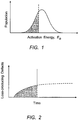
- the active form of hydrogen reacts with existing sites in the glass to form loss-causing defects. Data to date indicates that the reaction occurs with a broad distribution of activation energies. This is illustrated in Fig. 1 , which shows the number density of sites with activation energy, E a .
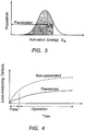
- Fig. 1 which indicates the population of defects that have reacted with available hydrogen due to exposure at some temperature for some time. As time progresses, more sites are consumed and the growth of the population of reacted sites grows to some asymptotic limit because there is a finite set of glass sites that hydrogen can occupy. The extent of reaction and creation of loss-producing defects grows with time, as illustrated in Fig. 2 .
- Optical fibers such as transmission fiber and erbium-doped fiber can be sufficiently sensitive to reaction with hydrogen at typical operating temperatures and hydrogen levels that the change in optical loss over time is unacceptable.
- passivation procedures have been developed to produce fibers that are more stable over time. Successful passivation reacts the lowest-lying sites and thereby slows the subsequent reaction at operating conditions without inducing unacceptable initial background loss.
- deuterium may be substituted for hydrogen. Since deuterium is chemically similar to hydrogen, the kinetics of reaction with available glass sites is also very similar. However, because of the increase in atomic weight, the absorption spectra associated with deuterium species in glass is radically different than hydrogen.
- the hydroxyl overtone around 1.38 microns in silica which is responsible for most of the optical loss in the telecommunications window around 1.55 microns, is shifted away from the window. This reduces the impact on loss of reaction with deuterium. Thus passivation with deuterium can induce relatively little attenuation of the signal wavelength.
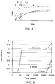
- Figs. 3 and 4 show a population of sites reacted with deuterium during passivation.
- the induced loss is small and can be accounted for prior to placing the optical fiber in service.
- the hydrogen sites remaining (the sites that were not passivated) have higher activation energy than those consumed during passivation, so the reaction rate proceeds more slowly.
- the additional optical loss in service should therefore be small, despite the higher molar absorption of hydrogen. This renders the fiber much more stable over time than a non-passivated fiber.
- Passivation essentially accelerates the consumption of the lowest-lying sites, using accelerated conditions, i.e., much higher temperature and gas pressure than anticipated in service, and fills the sites with species that are relatively loss-less.
- the concepts discussed can be used to allow accurate prediction of the growth of optical loss in a fiber during its service lifetime. Since the reaction with deuterium shifts the optical absorption of the reacted defects away from the wavelength of operation, the loss induced during passivation with deuterium is relatively small. Focus has therefore been on calculating the expected growth of loss during operation, and determining an appropriate level of passivation to attain adequate end-of-life characteristics. Any attenuation due to passivation has been relatively minor and treated as a necessary cost. Since typical passivation conditions may entail temperatures in excess of 100°C for many hours, in some cases the passivation process is limited by coating degradation or simple fiber processing cost, rather than by induced optical loss.
- Fibers exhibit similar excessive loss due to passivation, such as erbium doped fibers intended for exposure to harsh environments or high-reliability applications. These fibers may have high concentrations of aluminum.
- Curve (b) shows more aggressive passivation (at higher temperature, for example), resulting in more incurred passivation loss, but subsequent reactivity has been slowed sufficiently so that after long service time the total incurred loss is lower than in curve (a). Yet more aggressive passivation in curve (c) renders the fiber quite stable to degradation in service, but this does not compensate for the high passivation loss, and the end-of-life loss is higher than curve (b). Thus it is shown that the passivation process can be too severe as well as too mild. While it would normally be assumed that an effective passivation process may only need to account for a passivation threshold, the afore-stated understanding establishes that optimum passivation conditions have both a maximum as well as a minimum. Thus in designing a deuterium passivation process it is desirable to calculate not only the lower limits of process conditions but the upper limits as well.
- One aspect of the invention is an experimental protocol for determining [ H *].
- the diffusion constant and solubility of H 2 in silica as a function of temperature and pressure can be obtained from the literature (e.g. Lemaire, Optical engineering, June 1981, V30, no 6, pp 781 equations 2 and 3 ).
- the hydrogen activity can be determined.
- the dominant activity is adsorption of H 2 directly onto the loss-generating site with subsequent splitting of the hydrogen- hydrogen bond.
- the activity has the form of an adsorption isotherm, with general form 1 + A 1 + A B ⁇ H 2 with [ H 2 ] determined directly from the diffusion and solubility, and A and B estimated experimentally.
- the model above can be fit based on experimental data from appropriate experiments to estimate the activity. Subsequent experiments are helpful in refining the activity to improve the accuracy of long-term prediction.
- a multimode fiber was fabricated with a Ge-P doped core.
- the optical fibers were treated in a heated furnace with an atmosphere of deuterium mixed with nitrogen. Nominal overall pressure was 1 atmosphere.
- simulations were performed to predict fiber end-of-life performance after passivation at 72C and 1 atm of deuterium for different times.
- the exposure durations of 4, 8 and 12 hrs are plotted in the Fig. 6 .
- In service conditions were assumed to be 25C and 10 -4 atm of hydrogen, with an operating lifetime of 10 yrs.
- the short passivation (4hrs) is inadequate for reacting a sufficient population of reactive sites while the long passivation (12hrs) is excessive.
- Minimum end-of-life loss is found at passivation duration of 8 hrs.
- the preferred treatments comprise an initial treatment in heated deuterium, followed by a drive-in anneal in an inert gas, e.g., nitrogen.
- an inert gas e.g., nitrogen.
- the inert gas drive-in allows diffusion of absorbed deuterium through the fiber, and allows the desired reactions to occur.
- the pressure of deuterium is 0.25 to 0.75 atmospheres and the preferred overall treatment period is in the range 18 to 30 hours, with a deuterium treatment period of two to six hours.
- the corresponding treatment temperature range is 65 to 100 degrees C.
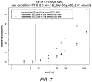
- Fig. 7 provides raw data measured from unpassivated fiber vs passivated fiber, measured at 1310 nm, at an accelerated condition of 70° C, 0.3 atmosphere H 2 .
- the optical fiber composition was 14% P 2 O 5 , 13% GeO 2 , 73% essentially SiO 2 .
- the horizontal axis is time at the accelerated condition in hours.
- the vertical axis is incremental loss in dB per kilometer.
- the vertical line at approximately 5 hours is a rough estimate of the time at the accelerated condition corresponding to end of life for exposure at 40 C ., 35 years, 0.01 atm hydrogen.
- the estimate of end of life loss for each fiber is given in the legend.
- the effect of passivation can be clearly seen as the unpassivated fiber (triangle symbol ⁇ ) stays strictly above the passivated fibers once the noise floor of the measurement is exceeded.
- compositions of primary interest are silica-based optical fibers co-doped with GeO 2 and P 2 O 5 .
- the mol ratio of GeO 2 to P 2 O 5 may vary widely, for example, from 0.5 to 10.
- the overall dopant concentration typically varies from 15 to 32 mol%, remainder SiO 2 .
- the phosphorus content is generally in the range 2 mol% to 20 mol%.
- Specific compositions of interest are GeO 2 20% +/- 3% with P 2 O 5 3% +/- 1 %, and GeO 2 13% +/- 3% with P 2 O 5 14% +/- 3%.
- Multimode fiber that is the subject of the foregoing description can be recognized as generally having a relatively large core diameter, typically greater than 10 microns. This property distinguishes the optical fiber from single mode optical fiber that typically has a core diameter of 6 microns or less.
Landscapes
- Chemical & Material Sciences (AREA)
- Life Sciences & Earth Sciences (AREA)
- Materials Engineering (AREA)
- Engineering & Computer Science (AREA)
- Chemical Kinetics & Catalysis (AREA)
- General Chemical & Material Sciences (AREA)
- Geochemistry & Mineralogy (AREA)
- Organic Chemistry (AREA)
- General Life Sciences & Earth Sciences (AREA)
- Toxicology (AREA)
- Health & Medical Sciences (AREA)
- Physics & Mathematics (AREA)
- Optics & Photonics (AREA)
- Glass Compositions (AREA)
- Optical Fibers, Optical Fiber Cores, And Optical Fiber Bundles (AREA)
Claims (12)
- Verfahren zum Passivieren einer optischen Faser, wobei die optische Faser SiO2 ist, das mit GeO2 und P2O5, co-dotiert ist, mit dem Schritt eines Erwärmens der optischen Faser in einer deuteriumhaltigen Atmosphäre bei einer Temperatur in dem Bereich von 65-100 Grad C für zumindest zwei Stunden,
wobei die Atmosphäre 0,25-0,75 Atmosphären Deuterium aufweist. - Das Verfahren gemäß Anspruch 1, bei dem die optische Faser mit GeO2 in dem Bereich von 15 Mol-% bis 30 Mol-% co-dotiert ist.
- Das Verfahren gemäß Anspruch 2, bei dem die Menge an P2O5 zumindest 2% beträgt.
- Das Verfahren gemäß Anspruch 1, bei dem die Atmosphäre 0,25-0,75 Atmosphären Deuterium aufweist, wobei der Rest Stickstoff ist.
- Das Verfahren gemäß Anspruch 1, bei dem die Zusammensetzung der optischen Faser 20 Mol-% +/- 3% GeO2 mit 3 Mol-% +/- 1 % P2O5 ist.
- Das Verfahren gemäß Anspruch 1, bei dem die Zusammensetzung der optischen Faser 13 Mol-% +/- 3% GeO2 mit 14 Mol-% +/- 3% P2O5 ist.
- Das Verfahren gemäß Anspruch 1, bei dem die optische Faser eine Mehrmodenfaser ist.
- Das Verfahren gemäß Anspruch 7, bei dem die optische Faser einen Kern mit einem Durchmesser von mehr als 10 Mikrometern aufweist.
- Das Verfahren gemäß Anspruch 1, bei dem die optische Faser nachfolgend in einer inerten Atmosphäre erwärmt wird.
- Das Verfahren gemäß Anspruch 1, bei dem die optische Faser für einen Zeitraum in dem Bereich von 16-26 Stunden in einer inerten Atmosphäre erwärmt wird.
- Das Verfahren gemäß Anspruch 10, bei dem die Passivierungsbedingungen 0,4 +/- 0,2 Atmosphären Deuterium für 3 +/- 1 Stunden, mit der Temperatur in dem Bereich von 82-92 Grad C sind.
- Verfahren zum Passivieren einer optischen Faser, wobei die optische Faser SiO2 ist, das mit GeO2 und P2O5 co-dotiert ist, mit einer Anfangsbehandlung der optischen Faser für 2 bis 6 Stunden in einer Atmosphäre mit 0,25-0,75 Atmosphären Deuterium, die erwärmt wird auf eine Temperatur in dem Bereich von 65-100 Grad C, gefolgt durch ein Eindring-Ausheilen in einem Inertgas für einen derartigen Zeitraum, dass der Gesamtbehandlungszeitraum in dem Bereich von 18 bis 30 Stunden liegt.
Applications Claiming Priority (2)
| Application Number | Priority Date | Filing Date | Title |
|---|---|---|---|
| US12/072,433 US8111961B2 (en) | 2008-02-26 | 2008-02-26 | Accelerated aging of phosphorus-doped optical fibers |
| EP08021945A EP2096088A1 (de) | 2008-02-26 | 2008-12-17 | Beschleunigte Alterung von phosphordotierten optischen Fasern |
Related Parent Applications (2)
| Application Number | Title | Priority Date | Filing Date |
|---|---|---|---|
| EP08021945.4 Division | 2008-12-17 | ||
| EP08021945A Division EP2096088A1 (de) | 2008-02-26 | 2008-12-17 | Beschleunigte Alterung von phosphordotierten optischen Fasern |
Publications (2)
| Publication Number | Publication Date |
|---|---|
| EP2196441A1 EP2196441A1 (de) | 2010-06-16 |
| EP2196441B1 true EP2196441B1 (de) | 2017-11-15 |
Family
ID=40671002
Family Applications (2)
| Application Number | Title | Priority Date | Filing Date |
|---|---|---|---|
| EP08021945A Withdrawn EP2096088A1 (de) | 2008-02-26 | 2008-12-17 | Beschleunigte Alterung von phosphordotierten optischen Fasern |
| EP10157306.1A Ceased EP2196441B1 (de) | 2008-02-26 | 2008-12-17 | Beschleunigte Alterung von phosphordotierten optischen Fasern |
Family Applications Before (1)
| Application Number | Title | Priority Date | Filing Date |
|---|---|---|---|
| EP08021945A Withdrawn EP2096088A1 (de) | 2008-02-26 | 2008-12-17 | Beschleunigte Alterung von phosphordotierten optischen Fasern |
Country Status (4)
| Country | Link |
|---|---|
| US (1) | US8111961B2 (de) |
| EP (2) | EP2096088A1 (de) |
| JP (1) | JP5506210B2 (de) |
| CN (1) | CN101597144B (de) |
Families Citing this family (16)
| Publication number | Priority date | Publication date | Assignee | Title |
|---|---|---|---|---|
| US8498046B2 (en) | 2008-12-04 | 2013-07-30 | Imra America, Inc. | Highly rare-earth-doped optical fibers for fiber lasers and amplifiers |
| US7450813B2 (en) | 2006-09-20 | 2008-11-11 | Imra America, Inc. | Rare earth doped and large effective area optical fibers for fiber lasers and amplifiers |
| US8445059B2 (en) * | 2008-02-26 | 2013-05-21 | Ofs Fitel, Llc | Accelerated aging of phosphorus-doped optical fibers |
| WO2013074078A1 (en) * | 2011-11-15 | 2013-05-23 | Corning Incorporated | Method of manufacturing optical fiber with selected draw tension |
| FR2971061B1 (fr) * | 2011-01-31 | 2013-02-08 | Draka Comteq France | Fibre optique a large bande passante et a faibles pertes par courbure |
| US8965163B2 (en) * | 2011-11-04 | 2015-02-24 | Corning Incorporated | Ge-P co-doped multimode optical fiber |
| US8588568B2 (en) | 2011-11-04 | 2013-11-19 | Corning Incorporated | Bend loss resistant multi-mode fiber |
| US8971683B2 (en) * | 2012-10-31 | 2015-03-03 | Corning Incorporated | Multimode optical fiber and systems comprising such fiber |
| LT3441425T (lt) | 2016-12-05 | 2021-06-25 | Furukawa Electric Co., Ltd. | Celiuliozės-aliuminio disperguota polietileno dervos kompozicinė medžiaga, granulės ir suformuotas gaminys, panaudojant ją, ir jos gamybos būdas |
| KR20200043998A (ko) | 2017-08-23 | 2020-04-28 | 후루카와 덴키 고교 가부시키가이샤 | 셀룰로오스 섬유 분산 폴리에틸렌 수지 복합재, 이를 이용한 성형체 및 펠릿, 이들의 제조 방법, 그리고 셀룰로오스 섬유 부착 폴리에틸렌 박막편의 리사이클 방법 |
| WO2019038868A1 (ja) | 2017-08-23 | 2019-02-28 | 古河電気工業株式会社 | セルロース繊維分散ポリエチレン樹脂複合材、これを用いた成形体及びペレット、これらの製造方法、並びにセルロース繊維付着ポリエチレン薄膜片のリサイクル方法 |
| WO2019039569A1 (ja) | 2017-08-23 | 2019-02-28 | 古河電気工業株式会社 | セルロース繊維分散ポリオレフィン樹脂複合材、これを用いたペレット及び成形体、並びにセルロース繊維分散ポリオレフィン樹脂複合材の製造方法 |
| CN111094430A (zh) | 2017-08-23 | 2020-05-01 | 古河电气工业株式会社 | 分散有纤维素纤维的聚烯烃树脂复合材料 |
| CN108545967A (zh) * | 2018-05-22 | 2018-09-18 | 浙江富春江光电科技有限公司 | 一种光纤氮气智能处理柜 |
| CN108751750A (zh) * | 2018-05-22 | 2018-11-06 | 浙江富春江光电科技有限公司 | 一种衰减稳定超高强度的光纤的制备方法 |
| WO2023192120A1 (en) * | 2022-04-01 | 2023-10-05 | Corning Incorporated | Methods of categorizing single mode optical fibers |
Family Cites Families (15)
| Publication number | Priority date | Publication date | Assignee | Title |
|---|---|---|---|---|
| US4339173A (en) * | 1975-09-08 | 1982-07-13 | Corning Glass Works | Optical waveguide containing P2 O5 and GeO2 |
| JPS6090852A (ja) * | 1983-10-22 | 1985-05-22 | Furukawa Electric Co Ltd:The | 光ファイバの処理方法 |
| JPS60215550A (ja) * | 1984-04-12 | 1985-10-28 | Sumitomo Electric Ind Ltd | 弗素とp↓2o↓5を含有する石英系ガラス光伝送用フアイバ |
| EP0673895A3 (de) * | 1994-03-24 | 1996-01-03 | At & T Corp | Optische Wellenleiter aus Glas die gegen durch Wasserstoff induzierten Dämpfungszunahmen passiviert sind. |
| US6499318B1 (en) * | 1994-03-24 | 2002-12-31 | Fitel Usa Corp. | Glass optical waveguides passivated against hydrogen-induced loss increases |
| TW434432B (en) * | 1998-01-19 | 2001-05-16 | Sumitomo Electric Industries | Optical waveguide path grating and method of manufacturing it |
| JP2001255564A (ja) * | 2000-03-09 | 2001-09-21 | Nippon Telegr & Teleph Corp <Ntt> | ラマン増幅用ファイバおよび光ファイバ線路 |
| DE60039600D1 (de) * | 2000-08-25 | 2008-09-04 | Draka Comteq Bv | Verfahren zur Verringerung der Wasserstoffempfindlichkeit von Glasfasern bei 1380-1410 nm |
| US20030084684A1 (en) * | 2001-10-19 | 2003-05-08 | Jds Uniphase Corporation | Method of reducing a hydrogen content of an optical fiber or preform |
| JP2005112690A (ja) * | 2003-10-10 | 2005-04-28 | Furukawa Electric Co Ltd:The | 光導波路の製造方法 |
| CN1251985C (zh) * | 2004-03-18 | 2006-04-19 | 烽火通信科技股份有限公司 | 一种降低光纤氢损的处理方法以及该方法所使用设备 |
| KR100651528B1 (ko) * | 2004-06-03 | 2006-11-29 | 삼성전자주식회사 | 광섬유의 수소 민감도를 감소하기 위한 방법 |
| CN101523257B (zh) * | 2005-11-18 | 2011-05-04 | 斯德莱特技术有限公司 | 具有减少氢感生损耗的光纤及其制造方法 |
| US7421174B2 (en) * | 2006-08-28 | 2008-09-02 | Furakawa Electric North America; Inc. | Multi-wavelength, multimode optical fibers |
| US8445059B2 (en) * | 2008-02-26 | 2013-05-21 | Ofs Fitel, Llc | Accelerated aging of phosphorus-doped optical fibers |
-
2008
- 2008-02-26 US US12/072,433 patent/US8111961B2/en active Active
- 2008-12-17 EP EP08021945A patent/EP2096088A1/de not_active Withdrawn
- 2008-12-17 EP EP10157306.1A patent/EP2196441B1/de not_active Ceased
-
2009
- 2009-02-10 CN CN2009100058694A patent/CN101597144B/zh not_active Expired - Fee Related
- 2009-02-26 JP JP2009043269A patent/JP5506210B2/ja not_active Expired - Fee Related
Non-Patent Citations (1)
| Title |
|---|
| None * |
Also Published As
| Publication number | Publication date |
|---|---|
| US20090211303A1 (en) | 2009-08-27 |
| EP2196441A1 (de) | 2010-06-16 |
| JP2009203157A (ja) | 2009-09-10 |
| EP2096088A1 (de) | 2009-09-02 |
| JP5506210B2 (ja) | 2014-05-28 |
| US8111961B2 (en) | 2012-02-07 |
| CN101597144B (zh) | 2013-10-30 |
| CN101597144A (zh) | 2009-12-09 |
Similar Documents
| Publication | Publication Date | Title |
|---|---|---|
| EP2196441B1 (de) | Beschleunigte Alterung von phosphordotierten optischen Fasern | |
| DK1930753T3 (en) | Optical fiber having a high Brillouin threshold strength and low bending | |
| EP2418523B1 (de) | Vertiefte multimodale Gradientenglasfaser | |
| US8980369B2 (en) | Accelerated aging of phosphorus-doped optical fibers | |
| EP2749917B1 (de) | Quarzglas Ausgangsmaterial zur Herstellung einer optischen Faser | |
| EP2856225B1 (de) | Multimodale glasfaser und system mit solch einer faser | |
| EP2541292B1 (de) | Multimode-Lichtleitfaser | |
| EP3715923B1 (de) | Singlemode-glasfaser mit ultrageringem verlust und grosser effektiver fläche und herstellungsverfahren dafür | |
| EP3111260B1 (de) | Multimodale optische faser mit hoher bandbreite über einen erweiterten wellenlängenbereich und entsprechendes multimodales optisches system | |
| EP3330755A1 (de) | Einzelmodusfaser mit ultraniedriger dämpfung und biegungsunempfindlichkeit | |
| EP3330756B1 (de) | Singlemode-glasfaser mit extrem niedriger dämpfung und grosser wirkfläche | |
| Ten | Ultra low-loss optical fiber technology | |
| Kanamori | Transmission loss of optical fibers; achievements in half a century | |
| US10261242B2 (en) | Optical fiber and method of producing an optical fiber | |
| Sato et al. | Ultra-low loss 0.1397 dB/km silica-core single-mode fiber | |
| JP4229123B2 (ja) | 光伝送路 | |
| CN110244402B (zh) | 一种超低损耗大有效面积单模光纤设计及其制造方法 | |
| EP1672396A1 (de) | Faseroptik | |
| Bruce | Silica glass-based fibers | |
| Sato et al. | Ultra-Low-Loss Silica-Core Fiber with 0.1397 dB/km | |
| Chang et al. | 2 Optical Fibers to Support CWDM |
Legal Events
| Date | Code | Title | Description |
|---|---|---|---|
| PUAI | Public reference made under article 153(3) epc to a published international application that has entered the european phase |
Free format text: ORIGINAL CODE: 0009012 |
|
| AC | Divisional application: reference to earlier application |
Ref document number: 2096088 Country of ref document: EP Kind code of ref document: P |
|
| AK | Designated contracting states |
Kind code of ref document: A1 Designated state(s): FR GB NL |
|
| RIN1 | Information on inventor provided before grant (corrected) |
Inventor name: VAIDYA, DURGESH SHIVRAM Inventor name: DIGIOVANNI, DAVID J. Inventor name: LUVALLE, MICHAEL Inventor name: OULUNDSEN, GEORGE E. Inventor name: LINGLE, ROBERT JR. |
|
| 17P | Request for examination filed |
Effective date: 20101216 |
|
| 17Q | First examination report despatched |
Effective date: 20120824 |
|
| RAP1 | Party data changed (applicant data changed or rights of an application transferred) |
Owner name: OFS FITEL, LLC |
|
| GRAP | Despatch of communication of intention to grant a patent |
Free format text: ORIGINAL CODE: EPIDOSNIGR1 |
|
| INTG | Intention to grant announced |
Effective date: 20170601 |
|
| GRAS | Grant fee paid |
Free format text: ORIGINAL CODE: EPIDOSNIGR3 |
|
| GRAA | (expected) grant |
Free format text: ORIGINAL CODE: 0009210 |
|
| AC | Divisional application: reference to earlier application |
Ref document number: 2096088 Country of ref document: EP Kind code of ref document: P |
|
| AK | Designated contracting states |
Kind code of ref document: B1 Designated state(s): FR GB NL |
|
| REG | Reference to a national code |
Ref country code: GB Ref legal event code: FG4D |
|
| REG | Reference to a national code |
Ref country code: FR Ref legal event code: PLFP Year of fee payment: 10 |
|
| REG | Reference to a national code |
Ref country code: NL Ref legal event code: FP |
|
| PLBE | No opposition filed within time limit |
Free format text: ORIGINAL CODE: 0009261 |
|
| STAA | Information on the status of an ep patent application or granted ep patent |
Free format text: STATUS: NO OPPOSITION FILED WITHIN TIME LIMIT |
|
| 26N | No opposition filed |
Effective date: 20180817 |
|
| PGFP | Annual fee paid to national office [announced via postgrant information from national office to epo] |
Ref country code: GB Payment date: 20201228 Year of fee payment: 13 Ref country code: FR Payment date: 20201227 Year of fee payment: 13 |
|
| PGFP | Annual fee paid to national office [announced via postgrant information from national office to epo] |
Ref country code: NL Payment date: 20201226 Year of fee payment: 13 |
|
| REG | Reference to a national code |
Ref country code: NL Ref legal event code: MM Effective date: 20220101 |
|
| GBPC | Gb: european patent ceased through non-payment of renewal fee |
Effective date: 20211217 |
|
| PG25 | Lapsed in a contracting state [announced via postgrant information from national office to epo] |
Ref country code: NL Free format text: LAPSE BECAUSE OF NON-PAYMENT OF DUE FEES Effective date: 20220101 |
|
| PG25 | Lapsed in a contracting state [announced via postgrant information from national office to epo] |
Ref country code: GB Free format text: LAPSE BECAUSE OF NON-PAYMENT OF DUE FEES Effective date: 20211217 |
|
| PG25 | Lapsed in a contracting state [announced via postgrant information from national office to epo] |
Ref country code: FR Free format text: LAPSE BECAUSE OF NON-PAYMENT OF DUE FEES Effective date: 20211231 |