EP2196609B1 - Beschlagteil für einen Treibstangenbeschlag - Google Patents
Beschlagteil für einen Treibstangenbeschlag Download PDFInfo
- Publication number
- EP2196609B1 EP2196609B1 EP09176580.0A EP09176580A EP2196609B1 EP 2196609 B1 EP2196609 B1 EP 2196609B1 EP 09176580 A EP09176580 A EP 09176580A EP 2196609 B1 EP2196609 B1 EP 2196609B1
- Authority
- EP
- European Patent Office
- Prior art keywords
- fitting
- housing
- fitting part
- part according
- espagnolette
- Prior art date
- Legal status (The legal status is an assumption and is not a legal conclusion. Google has not performed a legal analysis and makes no representation as to the accuracy of the status listed.)
- Not-in-force
Links
- 229910000831 Steel Inorganic materials 0.000 claims description 6
- 239000010959 steel Substances 0.000 claims description 6
- 230000000903 blocking effect Effects 0.000 claims description 2
- 230000008878 coupling Effects 0.000 description 4
- 238000010168 coupling process Methods 0.000 description 4
- 238000005859 coupling reaction Methods 0.000 description 4
- 230000009286 beneficial effect Effects 0.000 description 2
- 230000000994 depressogenic effect Effects 0.000 description 1
- 239000000523 sample Substances 0.000 description 1
Images
Classifications
-
- E—FIXED CONSTRUCTIONS
- E05—LOCKS; KEYS; WINDOW OR DOOR FITTINGS; SAFES
- E05D—HINGES OR SUSPENSION DEVICES FOR DOORS, WINDOWS OR WINGS
- E05D15/00—Suspension arrangements for wings
- E05D15/48—Suspension arrangements for wings allowing alternative movements
- E05D15/52—Suspension arrangements for wings allowing alternative movements for opening about a vertical as well as a horizontal axis
- E05D15/526—Safety devices
-
- E—FIXED CONSTRUCTIONS
- E05—LOCKS; KEYS; WINDOW OR DOOR FITTINGS; SAFES
- E05B—LOCKS; ACCESSORIES THEREFOR; HANDCUFFS
- E05B63/00—Locks or fastenings with special structural characteristics
- E05B63/18—Locks or fastenings with special structural characteristics with arrangements independent of the locking mechanism for retaining the bolt or latch in the retracted position
- E05B63/185—Preventing actuation of a bolt when the wing is open
-
- E—FIXED CONSTRUCTIONS
- E05—LOCKS; KEYS; WINDOW OR DOOR FITTINGS; SAFES
- E05C—BOLTS OR FASTENING DEVICES FOR WINGS, SPECIALLY FOR DOORS OR WINDOWS
- E05C19/00—Other devices specially designed for securing wings, e.g. with suction cups
- E05C19/02—Automatic catches, i.e. released by pull or pressure on the wing
-
- E—FIXED CONSTRUCTIONS
- E05—LOCKS; KEYS; WINDOW OR DOOR FITTINGS; SAFES
- E05C—BOLTS OR FASTENING DEVICES FOR WINGS, SPECIALLY FOR DOORS OR WINDOWS
- E05C9/00—Arrangements of simultaneously actuated bolts or other securing devices at well-separated positions on the same wing
- E05C9/02—Arrangements of simultaneously actuated bolts or other securing devices at well-separated positions on the same wing with one sliding bar for fastening when moved in one direction and unfastening when moved in opposite direction; with two sliding bars moved in the same direction when fastening or unfastening
- E05C9/021—Arrangements of simultaneously actuated bolts or other securing devices at well-separated positions on the same wing with one sliding bar for fastening when moved in one direction and unfastening when moved in opposite direction; with two sliding bars moved in the same direction when fastening or unfastening with rack and pinion mechanism
-
- E—FIXED CONSTRUCTIONS
- E05—LOCKS; KEYS; WINDOW OR DOOR FITTINGS; SAFES
- E05C—BOLTS OR FASTENING DEVICES FOR WINGS, SPECIALLY FOR DOORS OR WINDOWS
- E05C9/00—Arrangements of simultaneously actuated bolts or other securing devices at well-separated positions on the same wing
- E05C9/06—Arrangements of simultaneously actuated bolts or other securing devices at well-separated positions on the same wing with three or more sliding bars
- E05C9/063—Arrangements of simultaneously actuated bolts or other securing devices at well-separated positions on the same wing with three or more sliding bars extending along three or more sides of the wing or frame
-
- E—FIXED CONSTRUCTIONS
- E05—LOCKS; KEYS; WINDOW OR DOOR FITTINGS; SAFES
- E05Y—INDEXING SCHEME ASSOCIATED WITH SUBCLASSES E05D AND E05F, RELATING TO CONSTRUCTION ELEMENTS, ELECTRIC CONTROL, POWER SUPPLY, POWER SIGNAL OR TRANSMISSION, USER INTERFACES, MOUNTING OR COUPLING, DETAILS, ACCESSORIES, AUXILIARY OPERATIONS NOT OTHERWISE PROVIDED FOR, APPLICATION THEREOF
- E05Y2900/00—Application of doors, windows, wings or fittings thereof
- E05Y2900/10—Application of doors, windows, wings or fittings thereof for buildings or parts thereof
- E05Y2900/13—Type of wing
- E05Y2900/148—Windows
Definitions
- the invention relates to a fitting for an espagnolette fitting of a window hinged against a frame of a window with a movement of a longitudinally displaceable drive rod with the wings pivoted away from the frame blocking false lock, with a protruding button of the false lock and with an edge gear for driving the drive rod, said Edge gear, a part of the wing frictionally retaining in the frame latch and a guide for the button are arranged in a common housing.
- the fitting has a misoperation lock.
- the mishandling device acts as a catch, with which a pivoting opening position of the wing can be avoided when located in the rotary opening position drive rod drive.
- a fitting part is for example from the DE 25 07 910 B2 known and has a plate connected to the drive rod.
- the plate has recesses into which a cam engages the false-lock.
- the cam is connected to a button and pivotally mounted on the edge gear.
- the false-lock ensures that the espagnolette fitting is only adjusted can if the wing is in the frame.
- a disadvantage of the known fitting part is that the wing lying in the frame can be pressed by the button of the false lock. An in-frame position of the wing is not durable without locking the espagnolette fitting.
- the invention is based on the problem to further develop a fitting of the type mentioned that it is easy to assemble and that the wing is reliably held in the frame even in the unlocked state.
- the housing has a recess limited by ramps for receiving an elastically biased body of the latch.
- the leaf lying in the frame is frictionally held in its position by the catch.
- a locking of the espagnolette fitting is not required thanks to the invention to hold the wing in the frame with a designated force.
- the fitting part according to the invention can be particularly easy to assemble.
- recesses and openings in the profile of the window are kept low, so that the fitting part according to the invention is particularly suitable for windows with a concealed drive rod.
- the fitting part according to the invention can be manufactured particularly cost-effectively, because the housing has a recess bounded by ramps for receiving having an elastically biased body of the latch.
- the elastically biased body of the latch is to be arranged on the fitting part according to the invention opposite the component of the wing or the frame.
- the common housing can be particularly easy to assemble according to an advantageous embodiment of the invention, when the edge gear has a parallel to the drive rod of the espagnolette longitudinally displaceable rail part and when the rail part has coupling means for positive connection with the drive rod.
- the fitting part according to the invention can be particularly easily adapted to an intended backset of the window.
- the fitting part according to the invention is thus particularly versatile. This design also allows the concealed arrangement of the drive rod in the window.
- the drive rod must be accessible only from a mounting side of the common fitting part.
- the common fitting part is simply mounted on the window while the coupling means positively connected to the drive rod.
- the structural complexity for connecting the rail part with the drive rod is kept very low.
- connection of the fitting part according to the invention with adjacent sections of the espagnolette fitting has a particularly high stability when the housing has an elongate guide recess arranged parallel to the direction of movement of the rail part and if the coupling means has a web which is connected to the rail part and penetrates the guide recess.
- the housing has a cover plate with a cylindrical guide bearing for guiding a drive pinion of the edge gear. Furthermore, the fitting part according to the invention can thereby be mounted particularly easily.
- the fitting part according to the invention has a high stability and can be manufactured particularly cost-effectively, if the housing has a connected to the cover plate and the guide plate plastic part and if the cover plate and the guide plate are made of sheet steel.
- the guide plate and the cover plate are screwed, riveted or clipped to the plastic part.
- this allows the rail part, a drive pinion of the fitting and the probe simply in the plastic part.
- the false-lock designed according to another advantageous embodiment of the invention structurally particularly simple when the rail part has at least one recess and when the button engages positively in a protruding position in the recess and is separated in a depressed position of the recess.
- the protruding over the base part position characterizes in the mounted state of the espagnolette fitting remote from the frame position of the wing. If the wing is moved against the frame, the button comes out of the recess and releases the movement of the rail part.
- the button is structurally particularly simple according to another advantageous embodiment of the invention, when the button is pivotally mounted in the housing and is biased with a first lever arm out of the housing in the protruding position and penetrates with a second lever arm in the recess of the rail part ,
- the drive rod When espagnolettes with a hidden guide the drive rod, a profile of the window on individual, separate openings through which the drive rod is accessible.
- the fitting part according to the invention can be easily used in such a concealed guide the drive rod when the common housing has a designed to cover an opening in the window aperture.
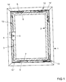
- FIG. 1 shows a window with a pivotable against a frame 1 wings 2 and with a drive rod fitting 3 for selectively locking and unlocking the wing 2 in the frame 1.
- the espagnolette fitting 3 has a fitting part 4 with a drive pinion 5, which can be coupled with a handle, not shown, and exemplarily two each a closure 6, 7 having fitting parts 8, 9 controls a longitudinally displaceable guided drive rod 10.
- the espagnolette fitting 3 has a scissor bearing 12 and a rotary / tilting bearing 13. In the corner regions of the wing 2 Eckumlenkeptache 14 are arranged.
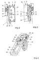
- FIG. 2 shows enlarged the drive pinion 5 having fitting part 4 of the espagnolette fitting 3 of Figure 1.
- the fitting 4 has a limited by ramps 15 recess 16 of the wing 2 in the frame 1 frictionally retaining latch 17.
- the catch 17 has a fitting part 4 opposite to the frame 1 arranged bushing 18 with one of spring elements 19 resiliently in the Recess 16 of the fitting part 4 prestressed body 20.
- the fitting part 4 has a housing 21 with a plastic part 22 and a cover plate 23 made of sheet steel.
- the cover plate 23 is bolted to the plastic part 22, riveted or clipped.
- the drive pinion 5 is mounted by means of a cylindrical guide bearing 24.
- the housing 21 has an aperture 25 for covering an opening 26 arranged in the wing 2.
- FIG. 3 shows the fitting part 4 FIG. 2 in a back view. It can be seen that the fitting part 4 coupling means 27 with a protruding from the housing 21 web 28 for the positive connection with the in FIG. 1 illustrated drive rod 10 has.
- the web 28 is guided in a guide plate 29 made of sheet steel.
- the guide plate 29 is bolted to the plastic part 22 of the housing 21, riveted or clipped.
- a button 30 a Fehlschaltsperre 31.
- the button 30 is biased against the sleeve 18 of the catch 17.
- FIG. 4 shows in a perspective view on the within the in FIGS. 2 and 3
- the drive pinion 5 meshes with a longitudinally displaceably guided in the housing 21 rail part 32 and thus forms an edge gear 33 for driving the in FIG. 1 shown drive rod 10.
- the rail part 32 is integral with the in FIG. 3
- the switch 30 of the false switch lock 31 has a first lever arm 35, with which it protrudes from the housing 21 and is biased against the bush 18 of the catch 17.
- a second lever arm 36 of the button 30 is opposite to the recesses 34 in the rail part 32.
- the button 30 is by means of a Torsion spring 37 biased into the position in which the first lever arm 35 protrudes from the housing 21 and the second lever arm 36, one of the recesses 34 of the rail part 32 penetrates.
- the false lock 31 blocks the movement of the drive rod 10 when the wing 2 is removed from the frame 1.
- the guide plate 29 has a guide recess 38 for the web 28 of the rail part 32.
- the button 30 has bearing shafts 39 for its guidance in the housing 21st
Landscapes
- Engineering & Computer Science (AREA)
- Mechanical Engineering (AREA)
- Structural Engineering (AREA)
- Operating, Guiding And Securing Of Roll- Type Closing Members (AREA)
- Power-Operated Mechanisms For Wings (AREA)
- Lock And Its Accessories (AREA)
- Window Of Vehicle (AREA)
Description
- Die Erfindung betrifft ein Beschlagteil für einen Treibstangenbeschlag eines gegen einen Rahmen schwenkbaren Flügels eines Fensters mit einer die Bewegung einer längsverschieblichen Treibstange bei von dem Rahmen weg geschwenktem Flügel blockierenden Fehlschaltsperre, mit einem hervorstehenden Taster der Fehlschaltsperre und mit einem Kantengetriebe zum Antrieb der Treibstange, wobei das Kantengetriebe, ein Teil eines den Flügel kraftschlüssig in dem Rahmen halternden Schnäppers und eine Führung für den Taster in einem gemeinsamen Gehäuse angeordnet sind.
- Aus der
EP 1 207 260 A2 ist ein Beschlagteil der eingangs genannten Art bekannt geworden. Das Beschlagteil hat eine Fehlbedienungssperre. Die Fehlbedienungssperre wirkt als Schnäpper, mit dem eine Schwenköffnungsstellung des Flügels bei in Dreh- Öffnungsstellung befindlichem Treibstangenantrieb vermieden werden kann. - Ein Beschlagteil ist beispielsweise aus der
DE 25 07 910 B2 bekannt und hat eine mit der Treibstange verbundene Platte. Die Platte weist Ausnehmungen auf, in die ein Nocken der Fehlschaltsperre eingreift. Der Nocken ist mit einem Taster verbunden und an dem Kantengetriebe schwenkbar gelagert. Damit muss nur ein einziges Beschlagteil für die Fehlschaltsperre und das Kantengetriebe an dem Fenster montiert werden. Die Fehlschaltsperre stellt sicher, dass der Treibstangenbeschlag nur verstellt werden kann, wenn der Flügel in dem Rahmen liegt. Nachteilig bei dem bekannten Beschlagteil ist, dass der im Rahmen liegende Flügel von dem Taster der Fehlschaltsperre aufgedrückt werden kann. Eine im Rahmen liegende Stellung des Flügels ist ohne Verriegelung des Treibstangenbeschlages nicht haltbar. - Aus der
DE 200 20 665 U1 ist eine Fehlschaltsperre bekannt geworden, bei der eine Lasche über einem Kantengetriebe hervorsteht. Bei einer Bewegung des Flügels gegen den Rahmen wird die Lasche gegen die Kraft einer Feder verschoben. Die Federkraft ist genau entgegen der Schließrichtung des Flügels gerichtet, so dass auch hier der Flügel von der Fehlschaltsperre aufgedrückt werden kann. - Der Erfindung liegt das Problem zugrunde, ein Beschlagteil der eingangs genannten Art so weiter zu bilden, dass es einfach zu montieren ist und dass der Flügel auch im unverriegelten Zustand zuverlässig in dem Rahmen gehalten ist.
- Dieses Problem wird erfindungsgemäß dadurch gelöst, dass das Gehäuse eine von Rampen begrenzte Ausnehmung zur Aufnahme eines elastisch vorgespannten Körpers des Schnäppers aufweist.
- Durch diese Gestaltung wird der im Rahmen liegende Flügel von dem Schnäpper kraftschlüssig in seiner Lage gehalten. Eine Verriegelung des Treibstangenbeschlages ist dank der Erfindung nicht erforderlich, um den Flügel im Rahmen mit einer vorgesehenen Kraft zu halten. Da der Schnäpper, die Fehlschaltsperre und das Kantengetriebe in nur einem einzigen Gehäuse angeordnet sind, lässt sich das erfindungsgemäße Beschlagteil besonders einfach montieren. Weiterhin werden Ausnehmungen und Durchbrüche im Profil des Fensters gering gehalten, so dass das erfindungsgemäße Beschlagteil besonders für Fenster mit einer verdeckt angeordneten Treibstange geeignet ist. Das erfindungsgemäße Beschlagteil lässt sich jedoch besonders kostengünstig fertigen, weil das Gehäuse eine von Rampen begrenzte Ausnehmung zur Aufnahme eines elastisch vorgespannten Körpers des Schnäppers aufweist. Durch diese Gestaltung ist der elastisch vorgespannte Körper des Schnäppers an dem dem erfindungsgemäßen Beschlagteil gegenüberliegenden Bauteil des Flügels oder des Rahmens anzuordnen.
- Das gemeinsame Gehäuse lässt sich gemäß einer vorteilhaften Weiterbildung der Erfindung besonders einfach montieren, wenn das Kantengetriebe ein parallel zur Treibstange des Treibstangenbeschlages längsverschiebliches Schienenteil hat und wenn das Schienenteil Koppelmittel zur formschlüssigen Verbindung mit der Treibstange hat. Hierdurch ist es nicht erforderlich, ein Antriebsritzel des Kantengetriebes mit der Treibstange des Treibstangenbeschlages direkt zu koppeln. Damit lässt sich das erfindungsgemäße Beschlagteil besonders einfach auf ein vorgesehenes Dornmaß des Fensters anpassen. Das erfindungsgemäße Beschlagteil ist hierdurch besonders vielseitig einsetzbar. Diese Gestaltung ermöglicht zudem die verdeckte Anordnung der Treibstange in dem Fenster. Die Treibstange muss dabei ausschließlich von einer Montageseite des gemeinsamen Beschlagteils zugänglich sein. Im einfachsten Fall wird das gemeinsame Beschlagteil einfach an dem Fenster montiert und dabei die Koppelmittel formschlüssig mit der Treibstange verbunden. Der bauliche Aufwand zur Verbindung des Schienenteils mit der Treibstange wird dabei besonders gering halten.
- Die Verbindung des erfindungsgemäßen Beschlagteils mit angrenzenden Abschnitten des Treibstangenbeschlages weist eine besonders hohe Stabilität auf, wenn das Gehäuse eine parallel zur Bewegungsrichtung des Schienenteils angeordnete, lang gestreckte Führungsausnehmung aufweist und wenn die Koppelmittel einen mit dem Schienenteil verbundenen, die Führungsausnehmung durchdringenden Steg haben.
- Zur weiteren Erhöhung der Stabilität der Verbindung des erfindungsgemäßen Beschlagteils mit angrenzenden Abschnitten des Treibstangenbeschlages trägt es bei, wenn das Gehäuse eine Führungsplatte mit der Führungsausnehmung aufweist.
- Zur weiteren Erhöhung der Stabilität der Verbindung des erfindungsgemäßen Beschlagteils mit angrenzenden Abschnitten des Treibstangenbeschlages trägt es bei, wenn der Steg und das Schienenteil einstückig aus Stahlblech gefertigt sind.
- Zur Erhöhung der Stabilität des Kantengetriebes des erfindungsgemäßen Beschlagteils trägt es bei, wenn das Gehäuse eine Deckplatte mit einem zylindrischen Führungslager zur Führung eines Antriebsritzels des Kantengetriebes hat. Weiterhin lässt sich das erfindungsgemäße Beschlagteil hierdurch besonders einfach montieren.
- Das erfindungsgemäße Beschlagteil hat eine hohe Stabilität und lässt sich besonders kostengünstig fertigen, wenn das Gehäuse ein mit der Deckplatte und der Führungsplatte verbundenes Kunststoffteil hat und wenn die Deckplatte und die Führungsplatte aus Stahlblech gefertigt sind.
- Zur Vereinfachung der Montage des erfindungsgemäßen Beschlagteils trägt es bei, wenn die Führungsplatte und die Deckplatte mit dem Kunststoffteil verschraubt, vernietet oder verklipst sind. Im einfachsten Fall lassen sich hierdurch das Schienenteil, ein Antriebsritzel des Beschlagteils und der Taster einfach in dem Kunststoffteil einsetzen. Nach der Montage der Führungsplatte und der Deckplatte ist das erfindungsgemäße Beschlagteil vollständig montiert.
- Die Fehlschaltsperre gestaltet sich gemäß einer anderen vorteilhaften Weiterbildung der Erfindung konstruktiv besonders einfach, wenn das Schienenteil zumindest eine Ausnehmung hat und wenn der Taster in einer hervorstehenden Stellung in die Ausnehmung formschlüssig eingreift und in einer eingedrückten Stellung von der Ausnehmung getrennt ist. Die über das Grundteil überstehende Stellung kennzeichnet im montierten Zustand des Treibstangenbeschlages die von dem Rahmen entfernte Stellung des Flügels. Wird der Flügel gegen den Rahmen bewegt, gelangt der Taster aus der Ausnehmung heraus und gibt die Bewegung des Schienenteils frei.
- Der Taster gestaltet sich gemäß einer anderen vorteilhaften Weiterbildung der Erfindung konstruktiv besonders einfach, wenn der Taster schwenkbar in dem Gehäuse gelagert ist und mit einem ersten Hebelarm aus dem Gehäuse heraus in die hervorstehende Stellung vorgespannt ist und mit einem zweiten Hebelarm in die Ausnehmung des Schienenteils eindringt.
- Bei Treibstangenbeschlägen mit einer verdeckten Führung der Treibstange weist ein Profil des Fensters einzelne, voneinander getrennte Öffnungen auf, durch die die Treibstange zugänglich ist. Das erfindungsgemäße Beschlagteil lässt sich bei einer solchen verdeckten Führung der Treibstange einfach einsetzen, wenn das gemeinsame Gehäuse eine zur Abdeckung einer Öffnung in dem Fenster ausgebildete Blende aufweist.
- Die Erfindung lässt zahlreiche Ausführungsformen zu. Zur weiteren Verdeutlichung ihres Grundprinzips ist eine davon in der Zeichnung dargestellt und wird nachfolgend beschrieben. Diese zeigt in
- Fig. 1
- ein Fenster mit einem Treibstangenbeschlag und einem erfindungsgemäßen Beschlagteil,
- Fig. 2
- vergrößert das erfindungsgemäße Beschlagteil aus
Figur 1 , - Fig. 3
- eine rückseitige Ansicht des erfindungsgemäßen Beschlagteils aus
Figur 2 , - Fig. 4
- perspektivisch bewegliche, innerhalb eines Gehäuses angeordnete Bauteile des Beschlagteils aus
Figur 1 . -
Figur 1 zeigt ein Fenster mit einem gegen einen Rahmen 1 schwenkbaren Flügel 2 und mit einem Treibstangenbeschlag 3 zur wahlweisen Verriegelung und Entriegelung des Flügels 2 in dem Rahmen 1. Zur Verdeutlichung ist der Flügel 2 geschnitten dargestellt. Der Treibstangenbeschlag 3 hat ein Beschlagteil 4 mit einem Antriebsritzel 5, welches sich mit einer nicht dargestellten Handhabe koppeln lässt und beispielhaft zwei jeweils einen Verschluss 6, 7 aufweisende Beschlagteile 8, 9 über eine längsverschieblich geführte Treibstange 10 ansteuert. Weiterhin hat der Treibstangenbeschlag 3 ein Scherenlager 12 und ein Dreh-/ Kipplager 13. In den Eckbereichen des Flügels 2 sind Eckumlenkungen 14 angeordnet. -
Figur 2 zeigt vergrößert das das Antriebsritzel 5 aufweisende Beschlagteil 4 des Treibstangenbeschlages 3 aus Figur 1. Zur Verdeutlichung sind inFigur 2 strichpunktiert der Flügel 2 und der Rahmen 1 dargestellt. Das Beschlagteil 4 hat eine von Rampen 15 begrenzte Ausnehmung 16 eines den Flügel 2 in dem Rahmen 1 kraftschlüssig halternden Schnäppers 17. Der Schnäpper 17 hat eine dem Beschlagteil 4 gegenüberliegend an dem Rahmen 1 angeordnete Buchse 18 mit einem von Federelementen 19 federnd in die Ausnehmung 16 des Beschlagteils 4 vorgespannten Körper 20. Das Beschlagteil 4 weist ein Gehäuse 21 mit einem Kunststoffteil 22 und einer Deckplatte 23 aus Stahlblech auf. Die Deckplatte 23 ist mit dem Kunststoffteil 22 verschraubt, vernietet oder verklipst. An der Deckplatte 23 ist das Antriebsritzel 5 mittels eines zylindrischen Führungslagers 24 gelagert. Das Gehäuse 21 hat eine Blende 25 zur Abdeckung einer in dem Flügel 2 angeordneten Öffnung 26. -
Figur 3 zeigt das Beschlagteil 4 ausFigur 2 in einer rückseitigen Ansicht. Hierbei ist zu erkennen, dass das Beschlagteil 4 Koppelmittel 27 mit einem aus dem Gehäuse 21 herausragenden Steg 28 zur formschlüssigen Verbindung mit der inFigur 1 dargestellten Treibstange 10 hat. Der Steg 28 ist in einer aus Stahlblech gefertigten Führungsplatte 29 geführt. Die Führungsplatte 29 ist mit dem Kunststoffteil 22 des Gehäuses 21 verschraubt, vernietet oder verklipst. Weiterhin ist inFigur 3 ein Taster 30 einer Fehlschaltsperre 31 zu erkennen. Der Taster 30 ist gegen die Buchse 18 des Schnäppers 17 vorgespannt. -
Figur 4 zeigt in einer perspektivischen Darstellung auf die innerhalb des inFigur 2 und 3 dargestellten Gehäuses 21 angeordneten, beweglichen Bauteile und die Führungsplatte 29. Das Antriebsritzel 5 kämmt ein in dem Gehäuse 21 längsverschieblich geführtes Schienenteil 32 und bildet damit ein Kantengetriebe 33 zum Antrieb der inFigur 1 dargestellten Treibstange 10. Das Schienenteil 32 ist einstückig mit dem inFigur 3 dargestellten Steg 28 gefertigt und hat mehrere Ausnehmungen 34. Der Taster 30 der Fehlschaltsperre 31 hat einen ersten Hebelarm 35, mit dem er aus dem Gehäuse 21 herausragt und gegen die Buchse 18 des Schnäppers 17 vorgespannt ist. Ein zweiter Hebelarm 36 des Tasters 30 steht den Ausnehmungen 34 in dem Schienenteil 32 gegenüber. Der Taster 30 ist mittels einer Drehfeder 37 in die Stellung vorgespannt, in der der erste Hebelarm 35 aus dem Gehäuse 21 herausragt und der zweite Hebelarm 36 eine der Ausnehmungen 34 des Schienenteils 32 eindringt. Damit blockiert die Fehlschaltsperre 31 die Bewegung der Treibstange 10, wenn der Flügel 2 von dem Rahmen 1 entfernt ist. Die Führungsplatte 29 hat eine Führungsausnehmung 38 für den Steg 28 des Schienenteils 32. Der Taster 30 hat Lagerachsen 39 zu seiner Führung in dem Gehäuse 21.
Claims (11)
- Beschlagteil für einen Treibstangenbeschlag eines gegen einen Rahmen (1) schwenkbaren Flügels (2) eines Fensters mit einer die Bewegung einer längsverschieblichen Treibstange (10) bei von dem Rahmen (1) weg geschwenktem Flügel (2) blockierenden Fehlschaltsperre, mit einem hervorstehenden Taster der Fehlschaltsperre (31) und mit einem Kantengetriebe zum Antrieb der Treibstange, wobei das Kantengetriebe (33), ein Teil eines den Flügel (2) kraftschlüssig in dem Rahmen (1) halternden Schnäppers (17) und eine Führung für den Taster (30) in einem gemeinsamen Gehäuse (21) angeordnet sind, dadurch gekennzeichnet, dass das Gehäuse (21) eine von Rampen (15) begrenzte Ausnehmung (16) zur Aufnahme eines elastisch vorgespannten Körpers (20) des Schnäppers (17) aufweist.
- Beschlagteil nach Anspruch 1, dadurch gekennzeichnet, dass das Kantengetriebe (33) ein parallel zur Treibstange (10) des Treibstangenbeschlages (3) längsverschiebliches Schienenteil (32) hat und dass das Schienenteil (32) Koppelmittel (27) zur formschlüssigen Verbindung mit der Treibstange (10) hat.
- Beschlagteil nach Anspruch 2, dadurch gekennzeichnet, dass das Gehäuse (21) eine parallel zur Bewegungsrichtung des Schienenteils (32) angeordnete, lang gestreckte Führungsausnehmung (38) aufweist und dass die Koppelmittel (27) einen mit dem Schienenteil (32) verbundenen, die Führungsausnehmung (38) durchdringenden Steg (28) haben.
- Beschlagteil nach Anspruch 3, dadurch gekennzeichnet, dass das Gehäuse (21) eine Führungsplatte (29) mit der Führungsausnehmung (38) aufweist.
- Beschlagteil nach Anspruch 3 oder 4, dadurch gekennzeichnet, dass der Steg (28) und das Schienenteil (32) einstückig aus Stahlblech gefertigt sind.
- Beschlagteil nach einem der vorhergehenden Ansprüche, dadurch gekennzeichnet, dass das Gehäuse (21) eine Deckplatte (23) mit einem zylindrischen Führungslager (24) zur Führung eines Antriebsritzels (5) des Kantengetriebes (33) hat.
- Beschlagteil nach Anspruch 6, dadurch gekennzeichnet, dass das Gehäuse (21) ein mit der Deckplatte (23) und der Führungsplatte (29) verbundenes Kunststoffteil (22) hat und dass die Deckplatte (23) und die Führungsplatte (29) aus Stahlblech gefertigt sind.
- Beschlagteil nach Anspruch 7, dadurch gekennzeichnet, dass die Führungsplatte (29) und die Deckplatte (23) mit dem Kunststoffteil (22) verschraubt, vernietet oder verklipst sind.
- Beschlagteil nach einem der vorhergehenden Ansprüche, dadurch gekennzeichnet, dass das Schienenteil (32) zumindest eine Ausnehmung (34) hat und dass der Taster (30) in einer hervorstehenden Stellung in die Ausnehmung (34) formschlüssig eingreift und in einer eingedrückten Stellung von der Ausnehmung (34) getrennt ist.
- Beschlagteil nach Anspruch 9, dadurch gekennzeichnet, dass der Taster (30) schwenkbar in dem Gehäuse (21) gelagert ist und mit einem ersten Hebelarm (35) aus dem Gehäuse (21) heraus in die hervorstehende Stellung vorgespannt ist und mit einem zweiten Hebelarm (36) in die Ausnehmung (34) des Schienenteils (32) eindringt.
- Beschlagteil nach einem der vorhergehenden Ansprüche, dadurch gekennzeichnet, dass das gemeinsame Gehäuse (21) eine zur Abdeckung einer Öffnung (26) in dem Fenster ausgebildete Blende (25) aufweist.
Applications Claiming Priority (1)
| Application Number | Priority Date | Filing Date | Title |
|---|---|---|---|
| DE102008054562A DE102008054562A1 (de) | 2008-12-12 | 2008-12-12 | Beschlagteil für einen Treibstangenbeschlag |
Publications (3)
| Publication Number | Publication Date |
|---|---|
| EP2196609A2 EP2196609A2 (de) | 2010-06-16 |
| EP2196609A3 EP2196609A3 (de) | 2013-11-27 |
| EP2196609B1 true EP2196609B1 (de) | 2016-11-09 |
Family
ID=41716241
Family Applications (1)
| Application Number | Title | Priority Date | Filing Date |
|---|---|---|---|
| EP09176580.0A Not-in-force EP2196609B1 (de) | 2008-12-12 | 2009-11-20 | Beschlagteil für einen Treibstangenbeschlag |
Country Status (2)
| Country | Link |
|---|---|
| EP (1) | EP2196609B1 (de) |
| DE (1) | DE102008054562A1 (de) |
Families Citing this family (1)
| Publication number | Priority date | Publication date | Assignee | Title |
|---|---|---|---|---|
| DK202570024A1 (en) * | 2025-02-28 | 2026-02-20 | Vkr Holding As | A roof window comprising a handle with a locking mechanism. |
Family Cites Families (5)
| Publication number | Priority date | Publication date | Assignee | Title |
|---|---|---|---|---|
| DE2507910C3 (de) | 1975-02-24 | 1986-10-02 | Fa. Aug. Winkhaus, 4404 Telgte | Fehlbedienungssicherung für das Betätigungsgestänge eines Dreh-Kipp- Fensters |
| DE10056607C1 (de) * | 2000-11-15 | 2002-05-08 | Siegenia Frank Kg | Fehlbedienungssperre für Treibstangenbeschläge |
| DE20020665U1 (de) | 2000-11-29 | 2001-03-01 | Gretsch-Unitas GmbH Baubeschläge, 71254 Ditzingen | Verschlussgetriebe |
| DE20311828U1 (de) * | 2003-07-24 | 2003-10-02 | Gretsch-Unitas GmbH Baubeschläge, 71254 Ditzingen | Schließeinrichtung |
| ITBO20050036A1 (it) * | 2005-01-21 | 2006-07-22 | Gsg Internat Spa | Maniglia per infissi con apertura ad anta e ad anta ribaltata |
-
2008
- 2008-12-12 DE DE102008054562A patent/DE102008054562A1/de not_active Withdrawn
-
2009
- 2009-11-20 EP EP09176580.0A patent/EP2196609B1/de not_active Not-in-force
Also Published As
| Publication number | Publication date |
|---|---|
| EP2196609A3 (de) | 2013-11-27 |
| EP2196609A2 (de) | 2010-06-16 |
| DE102008054562A1 (de) | 2010-06-17 |
Similar Documents
| Publication | Publication Date | Title |
|---|---|---|
| EP2312102B1 (de) | Überwachungseinrichtung zur Überwachung einer Schließstellung eines Treibstangenbeschlages | |
| EP2251508B1 (de) | Schliessblech für Fenster oder Türen | |
| EP2196609B1 (de) | Beschlagteil für einen Treibstangenbeschlag | |
| EP2146032A1 (de) | Vorrichtung zum Öffnen und/oder Schliessen sowie zum Verriegeln eines geschlossenen Zustandes einer Verschlusseinrichtung zum Verschliessen einer Raumöffnung sowie Verschlusseinrichtung mit einer solchen Vorrichtung | |
| EP1298269B1 (de) | Betätigungsgetriebe, insbesondere Schloss für einen Treibstangenbeschlag sowie Treibstangenbeschlag mit einem solchen Betätigungsgetriebe | |
| DE10360188A1 (de) | Fehlschaltsicherung für ein Fenster, eine Tür oder dergleichen | |
| EP2754804B1 (de) | Verschluss für einen Treibstangenbeschlag | |
| EP1147278B1 (de) | Verschlussvorrichtung für den unterschlagenden flügel zweiflügeliger setzholzloser fenster, türen od. dgl. | |
| DE102005056151B4 (de) | Ecklageranordnung für Fenster, Türen oder dergleichen | |
| EP1498563B1 (de) | Spaltlüftungsvorrichtung | |
| EP1798360B1 (de) | Beschlagteil für einen Treibstangenbeschlag | |
| EP4446533B1 (de) | Fenster oder fenstertür mit einem auf einem hauptflügel aufgesetzten vorsatzflügel | |
| EP4174264B1 (de) | Flügelanordnung | |
| EP0668426A1 (de) | Beschlag für Fenster oder Türen | |
| EP1757760B1 (de) | Beschlagteil für einen Treibstangenbeschlag | |
| EP1835108B1 (de) | Fehlschaltsicherung für einen Treibstangenbeschlag eines Fensters oder einer Tür | |
| DE202007011079U1 (de) | Ausstellvorrichtung | |
| EP1757759B1 (de) | Beschlagteil für einen Treibstangenbeschlag | |
| EP1801334B1 (de) | Verschluss für einen Treibstangenbeschlag und Fenster mit einem solchen Verschluss | |
| EP3626918B1 (de) | Beschlag für ein fenster, fenster | |
| EP2330265B1 (de) | Fehlschaltsperre für einen Treibstangenbeschlag | |
| EP1867818B1 (de) | Verschluss für einen Treibstangenbeschlag und Fenster, Fenstertür oder dergleichen mit einem solchen Verschluss | |
| EP4089257A1 (de) | Überwachungseinrichtung für einen treibstangenbeschlag | |
| EP4628689A1 (de) | Öffnungsbegrenzungseinrichtung für einen treibstangenbeschlag | |
| EP1918496B1 (de) | Treibstangenbeschlag für einen gegen einen Rahmen schwenkbaren Flügel eines Fensters |
Legal Events
| Date | Code | Title | Description |
|---|---|---|---|
| PUAI | Public reference made under article 153(3) epc to a published international application that has entered the european phase |
Free format text: ORIGINAL CODE: 0009012 |
|
| AK | Designated contracting states |
Kind code of ref document: A2 Designated state(s): AT BE BG CH CY CZ DE DK EE ES FI FR GB GR HR HU IE IS IT LI LT LU LV MC MK MT NL NO PL PT RO SE SI SK SM TR |
|
| AX | Request for extension of the european patent |
Extension state: AL BA RS |
|
| PUAL | Search report despatched |
Free format text: ORIGINAL CODE: 0009013 |
|
| AK | Designated contracting states |
Kind code of ref document: A3 Designated state(s): AT BE BG CH CY CZ DE DK EE ES FI FR GB GR HR HU IE IS IT LI LT LU LV MC MK MT NL NO PL PT RO SE SI SK SM TR |
|
| AX | Request for extension of the european patent |
Extension state: AL BA RS |
|
| RIC1 | Information provided on ipc code assigned before grant |
Ipc: E05D 15/526 20060101AFI20131021BHEP Ipc: E05C 9/12 20060101ALI20131021BHEP Ipc: E05C 9/06 20060101ALI20131021BHEP |
|
| 17P | Request for examination filed |
Effective date: 20140331 |
|
| RBV | Designated contracting states (corrected) |
Designated state(s): AT BE BG CH CY CZ DE DK EE ES FI FR GB GR HR HU IE IS IT LI LT LU LV MC MK MT NL NO PL PT RO SE SI SK SM TR |
|
| REG | Reference to a national code |
Ref country code: DE Ref legal event code: R079 Ref document number: 502009013344 Country of ref document: DE Free format text: PREVIOUS MAIN CLASS: E05D0015526000 Ipc: E05B0063180000 |
|
| RIC1 | Information provided on ipc code assigned before grant |
Ipc: E05B 63/18 20060101AFI20160524BHEP Ipc: E05D 15/526 20060101ALI20160524BHEP Ipc: E05C 9/06 20060101ALI20160524BHEP Ipc: E05C 9/02 20060101ALI20160524BHEP Ipc: E05C 19/02 20060101ALI20160524BHEP |
|
| GRAP | Despatch of communication of intention to grant a patent |
Free format text: ORIGINAL CODE: EPIDOSNIGR1 |
|
| INTG | Intention to grant announced |
Effective date: 20160701 |
|
| GRAS | Grant fee paid |
Free format text: ORIGINAL CODE: EPIDOSNIGR3 |
|
| GRAA | (expected) grant |
Free format text: ORIGINAL CODE: 0009210 |
|
| AK | Designated contracting states |
Kind code of ref document: B1 Designated state(s): AT BE BG CH CY CZ DE DK EE ES FI FR GB GR HR HU IE IS IT LI LT LU LV MC MK MT NL NO PL PT RO SE SI SK SM TR |
|
| REG | Reference to a national code |
Ref country code: GB Ref legal event code: FG4D Free format text: NOT ENGLISH |
|
| REG | Reference to a national code |
Ref country code: AT Ref legal event code: REF Ref document number: 844080 Country of ref document: AT Kind code of ref document: T Effective date: 20161115 Ref country code: CH Ref legal event code: EP |
|
| REG | Reference to a national code |
Ref country code: IE Ref legal event code: FG4D Free format text: LANGUAGE OF EP DOCUMENT: GERMAN |
|
| REG | Reference to a national code |
Ref country code: DE Ref legal event code: R096 Ref document number: 502009013344 Country of ref document: DE |
|
| PG25 | Lapsed in a contracting state [announced via postgrant information from national office to epo] |
Ref country code: LV Free format text: LAPSE BECAUSE OF FAILURE TO SUBMIT A TRANSLATION OF THE DESCRIPTION OR TO PAY THE FEE WITHIN THE PRESCRIBED TIME-LIMIT Effective date: 20161109 |
|
| REG | Reference to a national code |
Ref country code: LT Ref legal event code: MG4D |
|
| REG | Reference to a national code |
Ref country code: NL Ref legal event code: MP Effective date: 20161109 |
|
| PG25 | Lapsed in a contracting state [announced via postgrant information from national office to epo] |
Ref country code: NL Free format text: LAPSE BECAUSE OF FAILURE TO SUBMIT A TRANSLATION OF THE DESCRIPTION OR TO PAY THE FEE WITHIN THE PRESCRIBED TIME-LIMIT Effective date: 20161109 Ref country code: LT Free format text: LAPSE BECAUSE OF FAILURE TO SUBMIT A TRANSLATION OF THE DESCRIPTION OR TO PAY THE FEE WITHIN THE PRESCRIBED TIME-LIMIT Effective date: 20161109 Ref country code: NO Free format text: LAPSE BECAUSE OF FAILURE TO SUBMIT A TRANSLATION OF THE DESCRIPTION OR TO PAY THE FEE WITHIN THE PRESCRIBED TIME-LIMIT Effective date: 20170209 Ref country code: SE Free format text: LAPSE BECAUSE OF FAILURE TO SUBMIT A TRANSLATION OF THE DESCRIPTION OR TO PAY THE FEE WITHIN THE PRESCRIBED TIME-LIMIT Effective date: 20161109 Ref country code: GR Free format text: LAPSE BECAUSE OF FAILURE TO SUBMIT A TRANSLATION OF THE DESCRIPTION OR TO PAY THE FEE WITHIN THE PRESCRIBED TIME-LIMIT Effective date: 20170210 |
|
| PG25 | Lapsed in a contracting state [announced via postgrant information from national office to epo] |
Ref country code: HR Free format text: LAPSE BECAUSE OF FAILURE TO SUBMIT A TRANSLATION OF THE DESCRIPTION OR TO PAY THE FEE WITHIN THE PRESCRIBED TIME-LIMIT Effective date: 20161109 Ref country code: PL Free format text: LAPSE BECAUSE OF FAILURE TO SUBMIT A TRANSLATION OF THE DESCRIPTION OR TO PAY THE FEE WITHIN THE PRESCRIBED TIME-LIMIT Effective date: 20161109 Ref country code: FI Free format text: LAPSE BECAUSE OF FAILURE TO SUBMIT A TRANSLATION OF THE DESCRIPTION OR TO PAY THE FEE WITHIN THE PRESCRIBED TIME-LIMIT Effective date: 20161109 Ref country code: ES Free format text: LAPSE BECAUSE OF FAILURE TO SUBMIT A TRANSLATION OF THE DESCRIPTION OR TO PAY THE FEE WITHIN THE PRESCRIBED TIME-LIMIT Effective date: 20161109 Ref country code: IS Free format text: LAPSE BECAUSE OF FAILURE TO SUBMIT A TRANSLATION OF THE DESCRIPTION OR TO PAY THE FEE WITHIN THE PRESCRIBED TIME-LIMIT Effective date: 20170309 Ref country code: PT Free format text: LAPSE BECAUSE OF FAILURE TO SUBMIT A TRANSLATION OF THE DESCRIPTION OR TO PAY THE FEE WITHIN THE PRESCRIBED TIME-LIMIT Effective date: 20170309 |
|
| REG | Reference to a national code |
Ref country code: CH Ref legal event code: PL |
|
| PG25 | Lapsed in a contracting state [announced via postgrant information from national office to epo] |
Ref country code: CH Free format text: LAPSE BECAUSE OF NON-PAYMENT OF DUE FEES Effective date: 20161130 Ref country code: LI Free format text: LAPSE BECAUSE OF NON-PAYMENT OF DUE FEES Effective date: 20161130 Ref country code: RO Free format text: LAPSE BECAUSE OF FAILURE TO SUBMIT A TRANSLATION OF THE DESCRIPTION OR TO PAY THE FEE WITHIN THE PRESCRIBED TIME-LIMIT Effective date: 20161109 Ref country code: SK Free format text: LAPSE BECAUSE OF FAILURE TO SUBMIT A TRANSLATION OF THE DESCRIPTION OR TO PAY THE FEE WITHIN THE PRESCRIBED TIME-LIMIT Effective date: 20161109 Ref country code: DK Free format text: LAPSE BECAUSE OF FAILURE TO SUBMIT A TRANSLATION OF THE DESCRIPTION OR TO PAY THE FEE WITHIN THE PRESCRIBED TIME-LIMIT Effective date: 20161109 Ref country code: EE Free format text: LAPSE BECAUSE OF FAILURE TO SUBMIT A TRANSLATION OF THE DESCRIPTION OR TO PAY THE FEE WITHIN THE PRESCRIBED TIME-LIMIT Effective date: 20161109 Ref country code: CZ Free format text: LAPSE BECAUSE OF FAILURE TO SUBMIT A TRANSLATION OF THE DESCRIPTION OR TO PAY THE FEE WITHIN THE PRESCRIBED TIME-LIMIT Effective date: 20161109 |
|
| REG | Reference to a national code |
Ref country code: DE Ref legal event code: R097 Ref document number: 502009013344 Country of ref document: DE |
|
| REG | Reference to a national code |
Ref country code: IE Ref legal event code: MM4A |
|
| PG25 | Lapsed in a contracting state [announced via postgrant information from national office to epo] |
Ref country code: BG Free format text: LAPSE BECAUSE OF FAILURE TO SUBMIT A TRANSLATION OF THE DESCRIPTION OR TO PAY THE FEE WITHIN THE PRESCRIBED TIME-LIMIT Effective date: 20170209 Ref country code: SM Free format text: LAPSE BECAUSE OF FAILURE TO SUBMIT A TRANSLATION OF THE DESCRIPTION OR TO PAY THE FEE WITHIN THE PRESCRIBED TIME-LIMIT Effective date: 20161109 |
|
| PLBE | No opposition filed within time limit |
Free format text: ORIGINAL CODE: 0009261 |
|
| STAA | Information on the status of an ep patent application or granted ep patent |
Free format text: STATUS: NO OPPOSITION FILED WITHIN TIME LIMIT |
|
| PG25 | Lapsed in a contracting state [announced via postgrant information from national office to epo] |
Ref country code: MC Free format text: LAPSE BECAUSE OF FAILURE TO SUBMIT A TRANSLATION OF THE DESCRIPTION OR TO PAY THE FEE WITHIN THE PRESCRIBED TIME-LIMIT Effective date: 20161109 Ref country code: LU Free format text: LAPSE BECAUSE OF NON-PAYMENT OF DUE FEES Effective date: 20161130 |
|
| REG | Reference to a national code |
Ref country code: FR Ref legal event code: ST Effective date: 20170901 |
|
| 26N | No opposition filed |
Effective date: 20170810 |
|
| GBPC | Gb: european patent ceased through non-payment of renewal fee |
Effective date: 20170209 |
|
| PG25 | Lapsed in a contracting state [announced via postgrant information from national office to epo] |
Ref country code: FR Free format text: LAPSE BECAUSE OF NON-PAYMENT OF DUE FEES Effective date: 20170109 |
|
| PG25 | Lapsed in a contracting state [announced via postgrant information from national office to epo] |
Ref country code: SI Free format text: LAPSE BECAUSE OF FAILURE TO SUBMIT A TRANSLATION OF THE DESCRIPTION OR TO PAY THE FEE WITHIN THE PRESCRIBED TIME-LIMIT Effective date: 20161109 Ref country code: IE Free format text: LAPSE BECAUSE OF NON-PAYMENT OF DUE FEES Effective date: 20161120 |
|
| PG25 | Lapsed in a contracting state [announced via postgrant information from national office to epo] |
Ref country code: GB Free format text: LAPSE BECAUSE OF NON-PAYMENT OF DUE FEES Effective date: 20170209 |
|
| PGFP | Annual fee paid to national office [announced via postgrant information from national office to epo] |
Ref country code: IT Payment date: 20171124 Year of fee payment: 9 Ref country code: BE Payment date: 20171124 Year of fee payment: 9 |
|
| PG25 | Lapsed in a contracting state [announced via postgrant information from national office to epo] |
Ref country code: CY Free format text: LAPSE BECAUSE OF FAILURE TO SUBMIT A TRANSLATION OF THE DESCRIPTION OR TO PAY THE FEE WITHIN THE PRESCRIBED TIME-LIMIT Effective date: 20161109 Ref country code: HU Free format text: LAPSE BECAUSE OF FAILURE TO SUBMIT A TRANSLATION OF THE DESCRIPTION OR TO PAY THE FEE WITHIN THE PRESCRIBED TIME-LIMIT; INVALID AB INITIO Effective date: 20091120 |
|
| PG25 | Lapsed in a contracting state [announced via postgrant information from national office to epo] |
Ref country code: MK Free format text: LAPSE BECAUSE OF FAILURE TO SUBMIT A TRANSLATION OF THE DESCRIPTION OR TO PAY THE FEE WITHIN THE PRESCRIBED TIME-LIMIT Effective date: 20161109 Ref country code: TR Free format text: LAPSE BECAUSE OF FAILURE TO SUBMIT A TRANSLATION OF THE DESCRIPTION OR TO PAY THE FEE WITHIN THE PRESCRIBED TIME-LIMIT Effective date: 20161109 |
|
| PG25 | Lapsed in a contracting state [announced via postgrant information from national office to epo] |
Ref country code: MT Free format text: LAPSE BECAUSE OF FAILURE TO SUBMIT A TRANSLATION OF THE DESCRIPTION OR TO PAY THE FEE WITHIN THE PRESCRIBED TIME-LIMIT Effective date: 20161109 |
|
| REG | Reference to a national code |
Ref country code: BE Ref legal event code: MM Effective date: 20181130 |
|
| PG25 | Lapsed in a contracting state [announced via postgrant information from national office to epo] |
Ref country code: IT Free format text: LAPSE BECAUSE OF NON-PAYMENT OF DUE FEES Effective date: 20181120 |
|
| PG25 | Lapsed in a contracting state [announced via postgrant information from national office to epo] |
Ref country code: BE Free format text: LAPSE BECAUSE OF NON-PAYMENT OF DUE FEES Effective date: 20181130 |
|
| PGFP | Annual fee paid to national office [announced via postgrant information from national office to epo] |
Ref country code: AT Payment date: 20191121 Year of fee payment: 11 |
|
| REG | Reference to a national code |
Ref country code: AT Ref legal event code: MM01 Ref document number: 844080 Country of ref document: AT Kind code of ref document: T Effective date: 20201120 |
|
| PG25 | Lapsed in a contracting state [announced via postgrant information from national office to epo] |
Ref country code: AT Free format text: LAPSE BECAUSE OF NON-PAYMENT OF DUE FEES Effective date: 20201120 |
|
| PGFP | Annual fee paid to national office [announced via postgrant information from national office to epo] |
Ref country code: DE Payment date: 20211122 Year of fee payment: 13 |
|
| REG | Reference to a national code |
Ref country code: DE Ref legal event code: R119 Ref document number: 502009013344 Country of ref document: DE |
|
| P01 | Opt-out of the competence of the unified patent court (upc) registered |
Effective date: 20230515 |
|
| PG25 | Lapsed in a contracting state [announced via postgrant information from national office to epo] |
Ref country code: DE Free format text: LAPSE BECAUSE OF NON-PAYMENT OF DUE FEES Effective date: 20230601 |