EP2196640B1 - Silencieux - Google Patents
Silencieux Download PDFInfo
- Publication number
- EP2196640B1 EP2196640B1 EP20090014710 EP09014710A EP2196640B1 EP 2196640 B1 EP2196640 B1 EP 2196640B1 EP 20090014710 EP20090014710 EP 20090014710 EP 09014710 A EP09014710 A EP 09014710A EP 2196640 B1 EP2196640 B1 EP 2196640B1
- Authority
- EP
- European Patent Office
- Prior art keywords
- jacket
- silencer
- chamber
- inlet
- exhaust gas
- Prior art date
- Legal status (The legal status is an assumption and is not a legal conclusion. Google has not performed a legal analysis and makes no representation as to the accuracy of the status listed.)
- Active
Links
Images


Classifications
-
- F—MECHANICAL ENGINEERING; LIGHTING; HEATING; WEAPONS; BLASTING
- F01—MACHINES OR ENGINES IN GENERAL; ENGINE PLANTS IN GENERAL; STEAM ENGINES
- F01N—GAS-FLOW SILENCERS OR EXHAUST APPARATUS FOR MACHINES OR ENGINES IN GENERAL; GAS-FLOW SILENCERS OR EXHAUST APPARATUS FOR INTERNAL-COMBUSTION ENGINES
- F01N1/00—Silencing apparatus characterised by method of silencing
- F01N1/02—Silencing apparatus characterised by method of silencing by using resonance
-
- F—MECHANICAL ENGINEERING; LIGHTING; HEATING; WEAPONS; BLASTING
- F01—MACHINES OR ENGINES IN GENERAL; ENGINE PLANTS IN GENERAL; STEAM ENGINES
- F01N—GAS-FLOW SILENCERS OR EXHAUST APPARATUS FOR MACHINES OR ENGINES IN GENERAL; GAS-FLOW SILENCERS OR EXHAUST APPARATUS FOR INTERNAL-COMBUSTION ENGINES
- F01N1/00—Silencing apparatus characterised by method of silencing
- F01N1/02—Silencing apparatus characterised by method of silencing by using resonance
- F01N1/023—Helmholtz resonators
-
- F—MECHANICAL ENGINEERING; LIGHTING; HEATING; WEAPONS; BLASTING
- F01—MACHINES OR ENGINES IN GENERAL; ENGINE PLANTS IN GENERAL; STEAM ENGINES
- F01N—GAS-FLOW SILENCERS OR EXHAUST APPARATUS FOR MACHINES OR ENGINES IN GENERAL; GAS-FLOW SILENCERS OR EXHAUST APPARATUS FOR INTERNAL-COMBUSTION ENGINES
- F01N1/00—Silencing apparatus characterised by method of silencing
- F01N1/08—Silencing apparatus characterised by method of silencing by reducing exhaust energy by throttling or whirling
- F01N1/10—Silencing apparatus characterised by method of silencing by reducing exhaust energy by throttling or whirling in combination with sound-absorbing materials
-
- F—MECHANICAL ENGINEERING; LIGHTING; HEATING; WEAPONS; BLASTING
- F01—MACHINES OR ENGINES IN GENERAL; ENGINE PLANTS IN GENERAL; STEAM ENGINES
- F01N—GAS-FLOW SILENCERS OR EXHAUST APPARATUS FOR MACHINES OR ENGINES IN GENERAL; GAS-FLOW SILENCERS OR EXHAUST APPARATUS FOR INTERNAL-COMBUSTION ENGINES
- F01N13/00—Exhaust or silencing apparatus characterised by constructional features
- F01N13/18—Construction facilitating manufacture, assembly, or disassembly
- F01N13/1838—Construction facilitating manufacture, assembly, or disassembly characterised by the type of connection between parts of exhaust or silencing apparatus, e.g. between housing and tubes, between tubes and baffles
-
- F—MECHANICAL ENGINEERING; LIGHTING; HEATING; WEAPONS; BLASTING
- F01—MACHINES OR ENGINES IN GENERAL; ENGINE PLANTS IN GENERAL; STEAM ENGINES
- F01N—GAS-FLOW SILENCERS OR EXHAUST APPARATUS FOR MACHINES OR ENGINES IN GENERAL; GAS-FLOW SILENCERS OR EXHAUST APPARATUS FOR INTERNAL-COMBUSTION ENGINES
- F01N2450/00—Methods or apparatus for fitting, inserting or repairing different elements
- F01N2450/22—Methods or apparatus for fitting, inserting or repairing different elements by welding or brazing
-
- F—MECHANICAL ENGINEERING; LIGHTING; HEATING; WEAPONS; BLASTING
- F01—MACHINES OR ENGINES IN GENERAL; ENGINE PLANTS IN GENERAL; STEAM ENGINES
- F01N—GAS-FLOW SILENCERS OR EXHAUST APPARATUS FOR MACHINES OR ENGINES IN GENERAL; GAS-FLOW SILENCERS OR EXHAUST APPARATUS FOR INTERNAL-COMBUSTION ENGINES
- F01N2470/00—Structure or shape of exhaust gas passages, pipes or tubes
- F01N2470/14—Plurality of outlet tubes, e.g. in parallel or with different length
-
- F—MECHANICAL ENGINEERING; LIGHTING; HEATING; WEAPONS; BLASTING
- F01—MACHINES OR ENGINES IN GENERAL; ENGINE PLANTS IN GENERAL; STEAM ENGINES
- F01N—GAS-FLOW SILENCERS OR EXHAUST APPARATUS FOR MACHINES OR ENGINES IN GENERAL; GAS-FLOW SILENCERS OR EXHAUST APPARATUS FOR INTERNAL-COMBUSTION ENGINES
- F01N2470/00—Structure or shape of exhaust gas passages, pipes or tubes
- F01N2470/18—Structure or shape of exhaust gas passages, pipes or tubes the axis of inlet or outlet tubes being other than the longitudinal axis of apparatus
Definitions
- the present invention relates to a silencer, in particular rear silencer, for an exhaust system of an internal combustion engine, in particular a motor vehicle engine, comprising a casing comprising a shell and two end walls, at least one exhaust gas inlet opening and at least one exhaust gas outlet opening and at least substantially housed in the housing silencer elements. It further relates to a method for producing such a silencer.
- Such mufflers are used as standard in motor vehicles in particular in order to reduce the noise level generated by the vehicle engine.
- a sleeve has hitherto been inserted into the jacket and a weld is made within the jacket.
- a welding within the shell is at least difficult, in particular in the case of a mounting of the silencer transverse to the direction of travel of the relevant motor vehicle.
- the publication DE 20 2007 010 754 U1 describes a muffler for the exhaust system of an internal combustion engine having a housing comprising a shell and two end walls and housed in the housing muffler elements.
- the muffler elements comprise an outlet pipe piece, which extends with one end through a shell-side exhaust gas outlet opening of the housing to the outside.
- the exhaust gas outlet opening is provided in a separately manufactured from the shell and then connectable with this closure plate through which a recess provided in the jacket can be closed.
- Other conventional mufflers for exhaust systems of internal combustion engines are in the publications DE 10 2004 059 540 B3 and DE 10 2005 026 376 A1 described.
- the invention has for its object to provide an improved muffler of the type mentioned, which is particularly easy to install, especially in a transverse installation.
- the silencer elements accommodated at least substantially in the housing comprise an inlet or outlet pipe section which is connected to a first end in a shell-side exhaust gas inlet. or exhaust gas outlet opening of the housing opens or extends through the latter to the outside, and that this Abgaseintritts- or exhaust outlet opening is provided in a separately manufactured from the jacket, then connectable with this closure plate, through which provided in the shell, in a shell end opening opening closable is.
- the muffler is particularly suitable for a transverse installation in the relevant motor vehicle. While the at least one exhaust gas inlet or exhaust gas outlet opening is provided on the shell side, the at least one exhaust gas outlet or exhaust gas inlet opening can be provided in particular on at least one of the two end sides.
- the muffler elements to be accommodated at least essentially in the housing, including the inlet or outlet pipe piece can be pushed into the jacket from the relevant jacket end side. In this case, these muffler elements can already be firmly connected to each other before, for example, welded. Welding within the shell is therefore not required.
- the recess provided in the jacket can then be closed by the closure plate, which is manufactured separately from the jacket and provided with the exhaust gas inlet or exhaust gas outlet opening.
- the silencer elements to be accommodated at least substantially in the housing are designed as a prefabricated, in particular dimensionally stable insert, separate from the jacket.
- This encompassing the at least substantially housed in the housing silencer elements Insert can then be inserted from the adjacent to the recess, then closable by a first end wall shell end side forth in the longitudinal direction of the housing in the jacket.
- the insert which is prefabricated separately from the casing, preferably comprises a support element which can be inserted into the casing in the sliding seat and to which the inlet or outlet pipe piece is firmly connected.
- the inlet or outlet pipe piece can therefore be connected in advance firmly with this support element. Welding within the shell is therefore no longer necessary.
- the inlet or outlet pipe piece is connectable via the closure plate with the shell.
- the insert via the connection of the inlet pipe piece with the closure plate and the connection of the closure plate with the shell in the shell can be fixed.
- the closure plate can already be connected to the inlet or outlet pipe piece, in particular welded, before or only after the insert has been inserted.
- the closure plate can then be fixedly connected to the jacket, in particular welded again.
- the jacket can in particular be longitudinally folded and / or welded.
- At least the first end wall is subsequently also welded, ie after the insertion of the silencer elements or of the comprehensive insert into the jacket, with the jacket. It can thus be welded all in one. So now all welds can be made by a single robot in a single operation be, which brings a particularly cost-effective production or assembly with it.
- the closure plate can be made larger than the recess, whereby an optimal closure of the recess is ensured and the stability is increased.
- the closure plate can also be made thicker than the jacket, which in turn results in a higher stability.
- the jacket can be made substantially thin-walled, thus weight is saved.
- the closure plate is provided with a collar.
- this collar can enclose at least a part of the outwardly extending end of the inlet or outlet pipe piece, resulting in particular again a higher stability.
- such a collar is also conceivable when the inlet or outlet tube piece opens into the gas inlet or gas outlet opening provided in the closure plate.
- the insert may in particular also comprise one or more further tube pieces firmly connected to the support element.
- a first chamber in particular a reflection chamber, and between between the support element and the first end wall adjacent to the closure plate the support member and the second end wall, a second chamber, in particular resonance chamber formed.
- the support element comprises two partitions having a spacing from one another in the housing longitudinal direction, between which a third chamber is formed, which may in particular be an absorption chamber.
- the partition wall provided between the first and third chambers preferably has a perforation, via which the first chamber communicates with the third chamber.
- the partition wall provided between the second and the third chamber is preferably not perforated.
- the inlet or outlet pipe piece may in particular have a perforation, via which it is connected to the first chamber.
- the insert preferably comprises one or more further tube pieces fixedly connected to the support element, which are respectively connected to the first chamber via a perforation, extend through the support element or the third chamber and through the second chamber, and in each case into one in the second Front wall provided gas outlet or gas inlet opening.
- one, two or even a plurality of such, each in a provided in the second end wall gas outlet or gas inlet opening pipe sections may be provided.
- one or more further firmly connected to the support member pipe pieces are conceivable, each in a in the first end wall provided gas outlet or gas inlet opening.
- the inlet or outlet pipe piece can pass through the support element or the third chamber and open with its second end in the second chamber.
- the insert comprises a resonance tube piece which is inserted at one end into the second end of the inlet or outlet tube piece and opens at its other end into the second chamber formed as a resonance chamber.
- the cross section of the resonance tube piece can be smaller than the cross section of the inlet or outlet tube piece in particular.
- the resonance tube piece can be supported in the second chamber via at least one connecting element on at least one pipe piece which opens into a gas outlet or gas inlet opening.
- the inventive method for producing a muffler according to the invention is characterized in that the at least substantially be housed in the housing silencer elements including the inlet or outlet pipe piece are prefabricated as particular dimensionally stable use separately from the jacket, that the jacket is made with a opening into a mantle end recess in that a closure plate having the exhaust gas inlet or exhaust gas outlet opening is manufactured separately from the jacket, that the insert is inserted in the jacket in the longitudinal direction of the housing in the jacket adjacent to the recess, then closable by an end wall in the longitudinal direction of the housing and that the recess provided in the jacket is then closed by the closure plate having the exhaust gas inlet opening, wherein the closure plate connected to the jacket, in particular welded becomes.
- the closure plate can already be connected, in particular welded, in advance or else only after the insert has been inserted, with the end of the inlet or outlet tube piece which opens out into the exhaust gas inlet or exhaust gas outlet opening or outwards through the latter.
- the silencer according to the invention can in principle be used both as a pre, main or as a rear muffler. Preferably, however, is the use as a rear muffler.
- the silencer according to the invention is particularly suitable for transverse installation. An exit is conceivable on one or both ends.
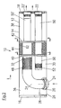
- Fig. 1 shows a schematic longitudinal sectional view of an exemplary embodiment of a muffler 10, in particular rear muffler, for an exhaust system of an internal combustion engine, in particular motor vehicle engine.
- the silencer can basically be used as a pre-, main- or as a rear silencer. Preferably, however, is the use as a rear muffler.
- Fig. 2 shows a schematic longitudinal sectional view rotated by 90 ° about its longitudinal axis muffler 10th
- the muffler 10 has a housing 12, which comprises a jacket 14 and two end walls 16, 18 and at least one exhaust gas inlet opening 20 and at least one exhaust gas outlet opening 22, 22 'has. In the present embodiment, an exhaust gas inlet opening 20 and two exhaust gas outlet openings 22, 22 'are provided.
- the silencer 10 also includes at least substantially housed in the housing 12, described in more detail below muffler elements.
- the silencer elements to be accommodated, at least substantially, in the housing 12 include, inter alia, an inlet pipe piece 24 which opens with a first end in a shell-side exhaust gas inlet opening 20 of the housing 12 or, as in the present embodiment, extends outwardly through the latter.
- this exhaust gas inlet opening 20 is provided in a separately manufactured from the jacket 14, then connectable with this closure plate 26 through which a provided in the jacket 14 recess 28 is subsequently closed, in a jacket end face in the Fig. 1 and 2 the left side of the jacket, opens.
- the at least substantially to be accommodated in the housing 12 silencer elements including the inlet pipe piece 24 are preferably designed as a separate from the shell 14 prefabricated, in particular dimensionally stable insert 30. In this case, this is the at least substantially housed in the housing 12 silencer elements including the inlet tube piece 24 comprehensive insert 30 of the adjacent to the recess 28, then closable by a first end wall 16 shell end side in the longitudinal direction L of the housing 12 in the shell 14 can be inserted.
- the insert 30, which is prefabricated separately from the casing 14, comprises a support element 32 which can be inserted into the casing 14 in a sliding fit, with which the inlet pipe piece 24 can be firmly connected from the outset.
- the insert 30 can thus be prefabricated with the inlet pipe piece 24 firmly connected to the support element 32 and then be inserted as a dimensionally stable unit in the jacket 14.
- the insert 30 can be fixed in the jacket 14 via the connection of the inlet tube piece 24 to the closure plate 26 and the connection of the closure plate 26 to the jacket 14.
- the inlet pipe 24 can already be connected in advance or only after the introduction of the insert with the closure plate 26, in particular welded.
- the closure plate 26 is connected after insertion of the insert in the jacket 14 with this, in particular welded again.
- the jacket 14 may in particular be longitudinally folded and / or welded.
- the first end wall 16 after insertion of the insert 30 with the jacket 14 are welded.
- the second end wall 18 can be welded to the jacket 14 again.
- the separate to the jacket 14 prefabricated insert 30 can thus be inserted or inserted from the one end face in the jacket 14.
- the jacket 14 is provided with a recess 26 which opens into the relevant end face and is only subsequently closed by the closure plate 26 having the exhaust gas inlet opening 20.
- the opening into the gas inlet opening 20 or through this outwardly extending inlet pipe section 24th can thus be connected from the outset firmly with the support member 32, whereby a subsequent welding within the shell 14 is omitted. Everything can now be welded together. Due to the shell-side inlet of the exhaust gas transverse installation of the muffler 10 in the relevant motor vehicle is possible.
- the closure plate 26 may in particular also be made larger than the recess 28, whereby a secure closing of the recess 28 is ensured and the stability is increased.
- the closure plate 26 may in particular also be made thicker than the jacket 14, whereby the stability is further increased.
- the insert 30 except the inlet pipe piece 24 one or more further, in particular fixedly connected to the support member 30, further described in detail below pipe pieces.
- a first chamber 36 in particular Reflection chamber
- a second chamber 38 in particular resonance chamber
- the support element 30 may comprise, in particular, two partitions or inner bottoms 40, 42 spaced apart from each other in the longitudinal direction of the housing L, between which a third chamber 44, in particular an absorption chamber, is formed.
- the partition wall 40 provided between the first and the third chamber 36 or 44 has in the present case a perforation 46 (cf. Fig. 5 ), via which the first chamber 36 communicates with the third chamber 44.
- partition wall 42 is not perforated.
- the inlet pipe piece 24 may have a perforation 48, via which it is connected to the first chamber 36.
- the insert 30 may include one or more further, in particular fixedly connected to the support member 32 pipe sections 50, 50 ', which are each connected via a perforation 52 to the first chamber 36, through the support member 32 and the third chamber 44 and through the second chamber 38 extend therethrough and each in a provided in the second end wall 18 gas outlet opening 22 and 22 'open.
- two such pipe sections 50, 50 ' are provided.
- only such a further pipe section opening into a gas outlet opening can be provided.
- more than two such each opening into a gas outlet opening further pipe sections may be provided.
- the inlet tube piece, the support member 32 and the third chamber 44 pass through and open with its second end in the second chamber 38, as is the case in the present embodiment.
- the insert 30 can also comprise a resonance tube piece 54 which is inserted at one end into the second end of the inlet tube piece 24 and opens at its other end into the second chamber 38, which is preferably designed as a resonance chamber.
- this resonance tube piece 54 may be supported in the second chamber 38 via at least one connecting element 56 at least one in a gas outlet opening 22, 22 'opening pipe section 50, 50'.
- the resonance pipe section 54 has a smaller cross-section than the inlet pipe piece 24. It passes through a provided in the partition wall opening 58 into the inlet pipe piece 24.
- the resonance pipe piece 24 is thus held on the one hand in the opening provided in the partition wall 42 and on the other hand via the connecting element 56 on at least one of the pipe sections 50, 50 'supported, whereby it again fixed relative to the support member 32.
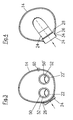
- Fig. 3 shows the muffler 10 in a schematic end view, in which the two exhaust gas outlet openings 22, 22 'can be seen, in each of which one of the two pipe sections 50, 50' opens.
- the point 60 is awarded, on which the jacket 14 is longitudinally folded and / or welded.
- Fig. 4 shows a schematic cross-sectional view of the muffler 10, taken along the line CC of Fig. 1 .
- the closure plate 26 may be enlarged not only relative to the recess 28, but for example, be provided with a collar 34 which encloses at least a portion of here, for example, through the exhaust inlet opening 20 to the outside extending end of the inlet tube piece 24.
- a collar 34 is basically also conceivable when the inlet pipe piece 24 opens into the exhaust gas inlet opening 20.
- Fig. 5 shows a further schematic cross-sectional view of the muffler 10, taken along the line AA Fig. 2 , In this case, in addition to the inlet pipe piece 24 and the two pipe sections 50, 50 'in particular, the perforation 46 of the partition 40 can be seen.
- Fig. 6 shows a further schematic cross-sectional view of the muffler 10, taken along the line BB of Fig. 2 , Based on this Fig. 6 it can be seen in particular that the partition wall 42 provided between the second chamber 38 and the third chamber 44 is designed without perforation. Moreover, in this illustration again the inlet pipe piece 24 and the two pipe sections 50, 50 'can be seen.
- the support member 32 may include a particular 62 of sound-absorbing material molding.
- the silencer according to the invention can be produced or mounted in particular by virtue of the fact that the silencer elements, including the inlet pipe piece 24, which are to be accommodated at least substantially in the housing 12, are separated from the insert 30 as a particularly dimensionally stable insert 30
- the opening into the exhaust gas inlet opening 20 or extending therethrough outwardly extending end of the inlet pipe piece 24 may be connected after insertion of the insert with the closure plate 26, in particular welded.
- the closure plate 26 in particular welded.
- a bonding after insertion of the insert into the jacket is preferred.
- the inlet pipe piece 24 may in particular comprise a generally in the longitudinal direction L of the housing 12 extending portion and a bent-off to the shell side portion.
- the pipe section 24 to be connected via the closure plate 26 to the jacket 14 is an inlet tube piece.
- this pipe section 24 forms a faithfulsroh published.
- the exhaust gas inlet opening 20 is then corresponding to the exhaust gas outlet opening, while the exhaust gas outlet openings 22, 22 'are corresponding to exhaust gas inlet openings.
Landscapes
- Engineering & Computer Science (AREA)
- Chemical & Material Sciences (AREA)
- Combustion & Propulsion (AREA)
- Mechanical Engineering (AREA)
- General Engineering & Computer Science (AREA)
- Exhaust Silencers (AREA)
Claims (15)
- Silencieux (10), en particulier silencieux secondaire, pour une installation de gaz d'échappement d'un moteur à combustion interne, en particulier d'un moteur de véhicule automobile, comprenant un boîtier (12) comportant une enveloppe (14) et deux parois frontales (16, 18), présentant au moins une ouverture d'entrée de gaz d'échappement et une ouverture de sortie de gaz d'échappement, et des éléments amortisseurs de bruit logés au moins essentiellement dans le boîtier (12), dans lequel lesdits éléments amortisseurs de bruit logés au moins essentiellement dans le boîtier (12) comprennent une pièce tubulaire d'entrée ou de sortie (24), qui débouche avec une première extrémité dans une ouverture d'entrée ou de sortie de gaz d'échappement (20) située côté enveloppe dans le boîtier (12) ou s'étend à travers cette ouverture vers l'extérieur, et dans lequel cette ouverture d'entrée ou de sortie de gaz d'échappement (20) est prévue dans une plaque d'obturation (26) fabriquée séparément de l'enveloppe (14) et susceptible d'être reliée ensuite à celle-ci, au moyen de laquelle un évidement (28) prévu dans l'enveloppe (14) est capable d'être obturé, caractérisé en ce que l'évidement (28) prévu dans l'enveloppe (14) débouche dans une face frontale de l'enveloppe.
- Silencieux selon la revendication 1,
caractérisé en ce que les éléments amortisseurs de bruit logés au moins essentiellement dans le boîtier (12), y compris la pièce tubulaire d'entrée ou de sortie (24) sont réalisés sous forme d'un insert préfabriqué séparément de l'enveloppe (14) et en particulier présentant une forme stable,
dans lequel l'insert (30) qui inclut les éléments amortisseurs de bruit à loger au moins essentiellement dans le boîtier (12) est de préférence susceptible d'être enfilé à l'intérieur de l'enveloppe (14) en direction longitudinale (L) du boîtier (12), depuis le côté frontal de l'enveloppe adjacent à l'évidement (28)'et susceptible d'être obturé ensuite par une première paroi frontale (16) et/ou l'insert (30) préfabriqué séparément de l'enveloppe (14) comprend un élément de soutien (32) susceptible d'être mis en place en coulissement dans l'enveloppe (14) et avec lequel est reliée fermement la pièce tubulaire d'entrée ou de sortie (24). - Silencieux selon l'une des revendications précédentes,
caractérisé en ce que la pièce tubulaire d'entrée ou de sortie (24) est susceptible d'être reliée avec l'enveloppe via la plaque d'obturation (26), dans lequel l'insert (30) est de préférence susceptible d'être fixé dans l'enveloppe (14) via la liaison de la pièce tubulaire d'entrée ou de sortie (24) avec la plaque d'obturation (26) et via la liaison de la plaque d'obturation (26) avec l'enveloppe (14). - Silencieux selon l'une des revendications précédentes,
caractérisé en ce que la pièce tubulaire d'entrée ou de sortie (24) est soudée avec la plaque d'obturation (26) et/ou en ce que la plaque d'obturation (26) est soudée avec l'enveloppe. - Silencieux selon l'une des revendications précédentes,
caractérisé en ce que l'enveloppe (14) est repliée et/ou soudée dans le sens de la longueur. - Silencieux selon l'une des revendications précédentes,
caractérisé en ce que la première paroi frontale (16) au moins est soudée avec l'enveloppe (14). - Silencieux selon l'une des revendications précédentes,
caractérisé en ce que la plaque d'obturation (26) est réalisée plus grande que l'évidement (28) et/ou en ce que la plaque d'obturation (26) est réalisée plus épaisse que l'enveloppe (12). - Silencieux selon l'une des revendications précédentes,
caractérisé en ce que la plaque d'obturation (26) est pourvue d'une collerette (34), ladite collerette (34) entourant de préférence au moins une partie de l'extrémité, s'étendant vers l'extérieur à travers l'ouverture d'entrée ou de sortie (20) des gaz d'échappement, de la pièce tubulaire d'entrée ou de sortie (24), et/ou en ce que l'insert (30) inclut, outre la pièce tubulaire d'entrée ou de sortie (24), une ou plusieurs autres pièces tubulaires reliées fermement avec l'élément de soutien (30). - Silencieux selon l'une des revendications précédentes,
caractérisé en ce qu'une première chambre (36), en particulier une chambre de réflexion, est formée entre l'élément de soutien (30) et la première paroi frontale (16) voisine de la plaque d'obturation (26), et en ce qu'une seconde chambre (38), en particulier une chambre de résonance, est formée entre l'élément de soutien (30) et la seconde paroi frontale (18),
dans lequel l'élément de soutien (30) comprend de préférence deux parois de séparation (40, 42) présentant une distance l'une de l'autre dans la direction longitudinale (L) du boîtier, entre lesquelles est formée une troisième chambre (44), en particulier une chambre d'absorption. - Silencieux selon l'une des revendications précédentes,
caractérisé en ce que la paroi de séparation (40) prévue entre la première et la troisième chambre (36 ou 44) présente une perforation (46), via laquelle la première chambre (36) communique avec la troisième chambre (44), et/ou en ce que la paroi de séparation (42) prévue entre la seconde et la troisième chambre (38 ou 44) n'est pas perforée. - Silencieux selon l'une des revendications précédentes,
caractérisé en ce que la pièce tubulaire d'entrée ou de sortie (24) présente une perforation (48) via laquelle elle est raccordée à la première chambre (36). - Silencieux selon l'une des revendications précédentes,
caractérisé en ce que l'insert (30) inclut une ou plusieurs autres pièces tubulaires (50, 50') reliées fermement à l'élément de soutien (32), lesquelles sont respectivement raccordées via une perforation (52) à la première chambre (36), s'étendent à travers l'élément de soutien (32) ou à travers la troisième chambre (44) ainsi qu'à travers la seconde chambre (38), et débouchent respectivement dans une ouverture de sortie ou d'entrée de gaz (22, 22') prévue dans la seconde paroi frontale. - Silencieux selon l'une des revendications précédentes,
caractérisé en ce que la pièce tubulaire d'entrée ou de sortie (24) traverse l'élément de soutien (32) ou respectivement la troisième chambre (44), et débouche dans la seconde chambre avec sa seconde extrémité. - Silencieux selon l'une des revendications précédentes,
caractérisé en ce que l'insert (30) inclut une pièce tubulaire de résonance (54), qui est mise en place avec une extrémité dans la seconde extrémité de la pièce tubulaire d'entrée ou de sortie (24) et qui débouche avec sa seconde extrémité dans la seconde chambre (38) réalisée à titre de chambre de résonance,
dans lequel la pièce tubulaire de résonance (54) est soutenue dans la seconde chambre (38) via au moins un élément de liaison (56) sur au moins une pièce tubulaire (50, 50') qui débouche dans une ouverture de sortie ou d'entrée de gaz (22, 22'). - Procédé pour la réalisation d'un silencieux selon l'une des revendications précédentes,
caractérisé en ce que
les éléments amortisseurs de bruit à loger au moins essentiellement dans le boîtier (12), y compris la pièce tubulaire d'entrée ou de sortie (24), sont préfabriqués séparément de l'enveloppe (14) sous la forme d'un insert (30) en particulier de forme stable, en ce que l'enveloppe (14) est fabriqué avec un évidement (28) qui débouche dans une face frontale de l'enveloppe, en ce qu'une plaque d'obturation (26) qui présente l'ouverture d'entrée ou de sortie de gaz d'échappement (20) est fabriquée séparément de l'enveloppe (14), en ce que l'insert (30) est enfilé dans l'enveloppe (14) en direction longitudinale (L) du boîtier (12) depuis une face frontale de l'enveloppe adjacente à l'évidement (28) et susceptible d'être ensuite obturée par une paroi frontale (16), et en ce que l'évidement (28) prévu dans l'enveloppe (14) est ensuite obturé par la plaque d'obturation (26) qui présente l'ouverture d'entrée ou de sortie de gaz d'échappement (20), et la plaque d'obturation (26) est reliée à l'enveloppe (14), en particulier soudée.
Applications Claiming Priority (1)
| Application Number | Priority Date | Filing Date | Title |
|---|---|---|---|
| DE200810062014 DE102008062014A1 (de) | 2008-12-12 | 2008-12-12 | Schalldämpfer |
Publications (3)
| Publication Number | Publication Date |
|---|---|
| EP2196640A2 EP2196640A2 (fr) | 2010-06-16 |
| EP2196640A3 EP2196640A3 (fr) | 2012-07-18 |
| EP2196640B1 true EP2196640B1 (fr) | 2014-10-08 |
Family
ID=41662363
Family Applications (1)
| Application Number | Title | Priority Date | Filing Date |
|---|---|---|---|
| EP20090014710 Active EP2196640B1 (fr) | 2008-12-12 | 2009-11-25 | Silencieux |
Country Status (2)
| Country | Link |
|---|---|
| EP (1) | EP2196640B1 (fr) |
| DE (1) | DE102008062014A1 (fr) |
Cited By (2)
| Publication number | Priority date | Publication date | Assignee | Title |
|---|---|---|---|---|
| US10196947B2 (en) | 2016-02-02 | 2019-02-05 | Kohler Co. | Muffler |
| US11421569B2 (en) | 2019-10-18 | 2022-08-23 | Tenneco Automotive Operating Company Inc. | Muffler |
Families Citing this family (7)
| Publication number | Priority date | Publication date | Assignee | Title |
|---|---|---|---|---|
| CA2897293C (fr) * | 2013-01-11 | 2017-05-02 | Futaba Industrial Co., Ltd. | Procede de montage de tube d'entree et procede de support de tube d'entree |
| DE102013208946A1 (de) | 2013-05-15 | 2014-11-20 | Bayerische Motoren Werke Aktiengesellschaft | Abgasanlage für eine Brennkraftmaschine und Verfahren zum Betreiben der Abgasanlage |
| DE102014103054A1 (de) | 2014-03-07 | 2015-09-10 | Tenneco Gmbh | Abgasschalldämpfer |
| DE102014107907A1 (de) | 2014-06-04 | 2015-12-17 | Eberspächer Exhaust Technology GmbH & Co. KG | Schalldämpfer |
| DE102016114317A1 (de) * | 2016-08-03 | 2018-02-08 | Friedrich Boysen Gmbh & Co. Kg | Baueinheit für eine Abgasanlage |
| EP3431732B1 (fr) | 2017-07-21 | 2020-04-22 | Bosal Emission Control Systems NV | Procédé de formation d'un collier dans un boîtier de silencieux |
| DE102020123069A1 (de) | 2020-09-03 | 2022-03-03 | Faurecia Emissions Control Technologies, Germany Gmbh | Abgasschalldämpfer sowie Verfahren zur Herstellung eines Abgasschalldämpfers |
Family Cites Families (10)
| Publication number | Priority date | Publication date | Assignee | Title |
|---|---|---|---|---|
| US3703938A (en) * | 1971-04-06 | 1972-11-28 | Nelson Muffler Corp | Exhaust muffler |
| US3687225A (en) * | 1971-04-06 | 1972-08-29 | Nelson Muffler Corp | Combined exhaust muffler with spark arrester |
| US3776366A (en) * | 1972-07-24 | 1973-12-04 | Outboard Marine Corp | Exhaust muffler |
| AT355878B (de) * | 1975-05-30 | 1980-03-25 | Vmw Ranshofen Berndorf Ag | Auspuffanlage |
| US4305477A (en) * | 1979-12-20 | 1981-12-15 | Deere & Company | Exhaust tuning means for internal combustion engines |
| US6467570B1 (en) * | 2001-05-15 | 2002-10-22 | Arvin Technologies, Inc. | Spark arrester with spark filter |
| GB2383604A (en) * | 2001-12-27 | 2003-07-02 | Wilson F G | Exhaust gas silencer with combined acoustic resonator chamber and spark arrester |
| DE102004059540B3 (de) * | 2004-12-09 | 2006-08-31 | J. Eberspächer GmbH & Co. KG | Vorrichtung zum Drosseln und Steuern von Strömungswegen, insbesondere in einem Schalldämpfer |
| DE102005026376C5 (de) * | 2005-06-08 | 2019-05-02 | Faurecia Emissions Control Technologies, Germany Gmbh | Fahrzeugschalldämpfer |
| DE202007010754U1 (de) * | 2007-08-02 | 2007-10-31 | Heinrich Gillet Gmbh | Gehäuse für Abgasanlagen |
-
2008
- 2008-12-12 DE DE200810062014 patent/DE102008062014A1/de not_active Withdrawn
-
2009
- 2009-11-25 EP EP20090014710 patent/EP2196640B1/fr active Active
Cited By (3)
| Publication number | Priority date | Publication date | Assignee | Title |
|---|---|---|---|---|
| US10196947B2 (en) | 2016-02-02 | 2019-02-05 | Kohler Co. | Muffler |
| US11421569B2 (en) | 2019-10-18 | 2022-08-23 | Tenneco Automotive Operating Company Inc. | Muffler |
| DE112020005026B4 (de) * | 2019-10-18 | 2024-12-19 | Tenneco Automotive Operating Company Inc. | Schalldämpfer |
Also Published As
| Publication number | Publication date |
|---|---|
| DE102008062014A1 (de) | 2010-06-17 |
| EP2196640A3 (fr) | 2012-07-18 |
| EP2196640A2 (fr) | 2010-06-16 |
Similar Documents
| Publication | Publication Date | Title |
|---|---|---|
| EP2196640A2 (fr) | Silencieux | |
| DE102011077183B4 (de) | Schalldämpfer und Herstellungsverfahren | |
| EP2362076B1 (fr) | Amortisseur de bruit | |
| DE102005026376C5 (de) | Fahrzeugschalldämpfer | |
| DE202018006874U1 (de) | Akustisch abgestimmter Schalldämpfer | |
| DE69918633T2 (de) | Ansauggeräuschdämpfer für Kraftfahrzeuge | |
| EP2131015B1 (fr) | Silencieux pour un système d'échappement | |
| EP1959106B2 (fr) | Silencieux pour un système d'échappement | |
| DE102008056350B4 (de) | Schalldämpfer und zugehöriges Herstellungsverfahren | |
| DE102007010486A1 (de) | Abgasnachbehandlungseinrichtung eines Kraftfahrzeugs | |
| DE102005054002B4 (de) | Schalldämpfer | |
| DE102017124750A1 (de) | Schalldämpfereinsatz, Schalldämpfer mit diesem und Verfahren zur Herstellung eines Schalldämpfereinsatzes | |
| DE102021113611A1 (de) | Schallminderer, Verfahren zu dessen Herstellung und Fluidleitungssystem mit einem solchen Schallminderer | |
| DE10045499B4 (de) | Auspuffsystem für ein Motorrad | |
| EP2639423B1 (fr) | Silencieux d'échappement | |
| EP1627997B1 (fr) | Silencieux d'échappement et méthode de fabrication | |
| EP4098851B1 (fr) | Silencieux | |
| DE102009023029A1 (de) | Schalldämpfer | |
| DE102013220686A1 (de) | Ansaugschalldämpfer | |
| EP1795719B1 (fr) | Silencieux pour un système d'échappement | |
| DE102014110101A1 (de) | Schalldämpfer | |
| WO2020148129A1 (fr) | Procédé de fabrication d'un silencieux, silencieux et véhicule | |
| WO2009018950A1 (fr) | Enceinte pour silencieux | |
| DE102014114254A1 (de) | Passiver Schalldämpfer mit Helmholtz-Resonator für mehrflutige Abgasanlagen | |
| DE102004042110B3 (de) | Schalldämpfer für eine Abgasanlage |
Legal Events
| Date | Code | Title | Description |
|---|---|---|---|
| PUAI | Public reference made under article 153(3) epc to a published international application that has entered the european phase |
Free format text: ORIGINAL CODE: 0009012 |
|
| AK | Designated contracting states |
Kind code of ref document: A2 Designated state(s): AT BE BG CH CY CZ DE DK EE ES FI FR GB GR HR HU IE IS IT LI LT LU LV MC MK MT NL NO PL PT RO SE SI SK SM TR |
|
| AX | Request for extension of the european patent |
Extension state: AL BA RS |
|
| PUAL | Search report despatched |
Free format text: ORIGINAL CODE: 0009013 |
|
| AK | Designated contracting states |
Kind code of ref document: A3 Designated state(s): AT BE BG CH CY CZ DE DK EE ES FI FR GB GR HR HU IE IS IT LI LT LU LV MC MK MT NL NO PL PT RO SE SI SK SM TR |
|
| AX | Request for extension of the european patent |
Extension state: AL BA RS |
|
| RIC1 | Information provided on ipc code assigned before grant |
Ipc: F01N 13/18 20100101ALI20120608BHEP Ipc: F01N 1/02 20060101AFI20120608BHEP Ipc: F01N 1/10 20060101ALI20120608BHEP |
|
| 17P | Request for examination filed |
Effective date: 20130107 |
|
| GRAP | Despatch of communication of intention to grant a patent |
Free format text: ORIGINAL CODE: EPIDOSNIGR1 |
|
| INTG | Intention to grant announced |
Effective date: 20140415 |
|
| GRAS | Grant fee paid |
Free format text: ORIGINAL CODE: EPIDOSNIGR3 |
|
| GRAA | (expected) grant |
Free format text: ORIGINAL CODE: 0009210 |
|
| AK | Designated contracting states |
Kind code of ref document: B1 Designated state(s): AT BE BG CH CY CZ DE DK EE ES FI FR GB GR HR HU IE IS IT LI LT LU LV MC MK MT NL NO PL PT RO SE SI SK SM TR |
|
| REG | Reference to a national code |
Ref country code: GB Ref legal event code: FG4D Free format text: NOT ENGLISH |
|
| REG | Reference to a national code |
Ref country code: AT Ref legal event code: REF Ref document number: 690760 Country of ref document: AT Kind code of ref document: T Effective date: 20141015 Ref country code: CH Ref legal event code: EP |
|
| REG | Reference to a national code |
Ref country code: IE Ref legal event code: FG4D Free format text: LANGUAGE OF EP DOCUMENT: GERMAN |
|
| REG | Reference to a national code |
Ref country code: DE Ref legal event code: R096 Ref document number: 502009010057 Country of ref document: DE Effective date: 20141120 |
|
| REG | Reference to a national code |
Ref country code: NL Ref legal event code: VDEP Effective date: 20141008 |
|
| REG | Reference to a national code |
Ref country code: LT Ref legal event code: MG4D |
|
| PG25 | Lapsed in a contracting state [announced via postgrant information from national office to epo] |
Ref country code: NL Free format text: LAPSE BECAUSE OF FAILURE TO SUBMIT A TRANSLATION OF THE DESCRIPTION OR TO PAY THE FEE WITHIN THE PRESCRIBED TIME-LIMIT Effective date: 20141008 |
|
| PG25 | Lapsed in a contracting state [announced via postgrant information from national office to epo] |
Ref country code: ES Free format text: LAPSE BECAUSE OF FAILURE TO SUBMIT A TRANSLATION OF THE DESCRIPTION OR TO PAY THE FEE WITHIN THE PRESCRIBED TIME-LIMIT Effective date: 20141008 Ref country code: IS Free format text: LAPSE BECAUSE OF FAILURE TO SUBMIT A TRANSLATION OF THE DESCRIPTION OR TO PAY THE FEE WITHIN THE PRESCRIBED TIME-LIMIT Effective date: 20150208 Ref country code: FI Free format text: LAPSE BECAUSE OF FAILURE TO SUBMIT A TRANSLATION OF THE DESCRIPTION OR TO PAY THE FEE WITHIN THE PRESCRIBED TIME-LIMIT Effective date: 20141008 Ref country code: PT Free format text: LAPSE BECAUSE OF FAILURE TO SUBMIT A TRANSLATION OF THE DESCRIPTION OR TO PAY THE FEE WITHIN THE PRESCRIBED TIME-LIMIT Effective date: 20150209 Ref country code: LT Free format text: LAPSE BECAUSE OF FAILURE TO SUBMIT A TRANSLATION OF THE DESCRIPTION OR TO PAY THE FEE WITHIN THE PRESCRIBED TIME-LIMIT Effective date: 20141008 Ref country code: NO Free format text: LAPSE BECAUSE OF FAILURE TO SUBMIT A TRANSLATION OF THE DESCRIPTION OR TO PAY THE FEE WITHIN THE PRESCRIBED TIME-LIMIT Effective date: 20150108 |
|
| PG25 | Lapsed in a contracting state [announced via postgrant information from national office to epo] |
Ref country code: SE Free format text: LAPSE BECAUSE OF FAILURE TO SUBMIT A TRANSLATION OF THE DESCRIPTION OR TO PAY THE FEE WITHIN THE PRESCRIBED TIME-LIMIT Effective date: 20141008 Ref country code: HR Free format text: LAPSE BECAUSE OF FAILURE TO SUBMIT A TRANSLATION OF THE DESCRIPTION OR TO PAY THE FEE WITHIN THE PRESCRIBED TIME-LIMIT Effective date: 20141008 Ref country code: GR Free format text: LAPSE BECAUSE OF FAILURE TO SUBMIT A TRANSLATION OF THE DESCRIPTION OR TO PAY THE FEE WITHIN THE PRESCRIBED TIME-LIMIT Effective date: 20150109 Ref country code: PL Free format text: LAPSE BECAUSE OF FAILURE TO SUBMIT A TRANSLATION OF THE DESCRIPTION OR TO PAY THE FEE WITHIN THE PRESCRIBED TIME-LIMIT Effective date: 20141008 Ref country code: LV Free format text: LAPSE BECAUSE OF FAILURE TO SUBMIT A TRANSLATION OF THE DESCRIPTION OR TO PAY THE FEE WITHIN THE PRESCRIBED TIME-LIMIT Effective date: 20141008 Ref country code: CY Free format text: LAPSE BECAUSE OF FAILURE TO SUBMIT A TRANSLATION OF THE DESCRIPTION OR TO PAY THE FEE WITHIN THE PRESCRIBED TIME-LIMIT Effective date: 20141008 |
|
| PG25 | Lapsed in a contracting state [announced via postgrant information from national office to epo] |
Ref country code: BE Free format text: LAPSE BECAUSE OF NON-PAYMENT OF DUE FEES Effective date: 20141130 |
|
| REG | Reference to a national code |
Ref country code: CH Ref legal event code: PL |
|
| REG | Reference to a national code |
Ref country code: DE Ref legal event code: R097 Ref document number: 502009010057 Country of ref document: DE |
|
| PG25 | Lapsed in a contracting state [announced via postgrant information from national office to epo] |
Ref country code: DK Free format text: LAPSE BECAUSE OF FAILURE TO SUBMIT A TRANSLATION OF THE DESCRIPTION OR TO PAY THE FEE WITHIN THE PRESCRIBED TIME-LIMIT Effective date: 20141008 Ref country code: RO Free format text: LAPSE BECAUSE OF FAILURE TO SUBMIT A TRANSLATION OF THE DESCRIPTION OR TO PAY THE FEE WITHIN THE PRESCRIBED TIME-LIMIT Effective date: 20141008 Ref country code: SK Free format text: LAPSE BECAUSE OF FAILURE TO SUBMIT A TRANSLATION OF THE DESCRIPTION OR TO PAY THE FEE WITHIN THE PRESCRIBED TIME-LIMIT Effective date: 20141008 Ref country code: EE Free format text: LAPSE BECAUSE OF FAILURE TO SUBMIT A TRANSLATION OF THE DESCRIPTION OR TO PAY THE FEE WITHIN THE PRESCRIBED TIME-LIMIT Effective date: 20141008 Ref country code: MC Free format text: LAPSE BECAUSE OF FAILURE TO SUBMIT A TRANSLATION OF THE DESCRIPTION OR TO PAY THE FEE WITHIN THE PRESCRIBED TIME-LIMIT Effective date: 20141008 Ref country code: CZ Free format text: LAPSE BECAUSE OF FAILURE TO SUBMIT A TRANSLATION OF THE DESCRIPTION OR TO PAY THE FEE WITHIN THE PRESCRIBED TIME-LIMIT Effective date: 20141008 Ref country code: CH Free format text: LAPSE BECAUSE OF NON-PAYMENT OF DUE FEES Effective date: 20141130 Ref country code: LI Free format text: LAPSE BECAUSE OF NON-PAYMENT OF DUE FEES Effective date: 20141130 |
|
| PLBE | No opposition filed within time limit |
Free format text: ORIGINAL CODE: 0009261 |
|
| STAA | Information on the status of an ep patent application or granted ep patent |
Free format text: STATUS: NO OPPOSITION FILED WITHIN TIME LIMIT |
|
| REG | Reference to a national code |
Ref country code: IE Ref legal event code: MM4A |
|
| REG | Reference to a national code |
Ref country code: FR Ref legal event code: ST Effective date: 20150731 |
|
| PG25 | Lapsed in a contracting state [announced via postgrant information from national office to epo] |
Ref country code: IT Free format text: LAPSE BECAUSE OF FAILURE TO SUBMIT A TRANSLATION OF THE DESCRIPTION OR TO PAY THE FEE WITHIN THE PRESCRIBED TIME-LIMIT Effective date: 20141008 |
|
| 26N | No opposition filed |
Effective date: 20150709 |
|
| GBPC | Gb: european patent ceased through non-payment of renewal fee |
Effective date: 20150108 |
|
| PG25 | Lapsed in a contracting state [announced via postgrant information from national office to epo] |
Ref country code: GB Free format text: LAPSE BECAUSE OF NON-PAYMENT OF DUE FEES Effective date: 20150108 Ref country code: IE Free format text: LAPSE BECAUSE OF NON-PAYMENT OF DUE FEES Effective date: 20141125 |
|
| PG25 | Lapsed in a contracting state [announced via postgrant information from national office to epo] |
Ref country code: FR Free format text: LAPSE BECAUSE OF NON-PAYMENT OF DUE FEES Effective date: 20141208 |
|
| REG | Reference to a national code |
Ref country code: AT Ref legal event code: MM01 Ref document number: 690760 Country of ref document: AT Kind code of ref document: T Effective date: 20141125 |
|
| PG25 | Lapsed in a contracting state [announced via postgrant information from national office to epo] |
Ref country code: SI Free format text: LAPSE BECAUSE OF FAILURE TO SUBMIT A TRANSLATION OF THE DESCRIPTION OR TO PAY THE FEE WITHIN THE PRESCRIBED TIME-LIMIT Effective date: 20141008 Ref country code: AT Free format text: LAPSE BECAUSE OF NON-PAYMENT OF DUE FEES Effective date: 20141125 |
|
| PG25 | Lapsed in a contracting state [announced via postgrant information from national office to epo] |
Ref country code: SM Free format text: LAPSE BECAUSE OF FAILURE TO SUBMIT A TRANSLATION OF THE DESCRIPTION OR TO PAY THE FEE WITHIN THE PRESCRIBED TIME-LIMIT Effective date: 20141008 |
|
| PG25 | Lapsed in a contracting state [announced via postgrant information from national office to epo] |
Ref country code: BG Free format text: LAPSE BECAUSE OF FAILURE TO SUBMIT A TRANSLATION OF THE DESCRIPTION OR TO PAY THE FEE WITHIN THE PRESCRIBED TIME-LIMIT Effective date: 20141008 |
|
| PG25 | Lapsed in a contracting state [announced via postgrant information from national office to epo] |
Ref country code: MT Free format text: LAPSE BECAUSE OF FAILURE TO SUBMIT A TRANSLATION OF THE DESCRIPTION OR TO PAY THE FEE WITHIN THE PRESCRIBED TIME-LIMIT Effective date: 20141008 Ref country code: HU Free format text: LAPSE BECAUSE OF FAILURE TO SUBMIT A TRANSLATION OF THE DESCRIPTION OR TO PAY THE FEE WITHIN THE PRESCRIBED TIME-LIMIT; INVALID AB INITIO Effective date: 20091125 Ref country code: LU Free format text: LAPSE BECAUSE OF NON-PAYMENT OF DUE FEES Effective date: 20141125 Ref country code: TR Free format text: LAPSE BECAUSE OF FAILURE TO SUBMIT A TRANSLATION OF THE DESCRIPTION OR TO PAY THE FEE WITHIN THE PRESCRIBED TIME-LIMIT Effective date: 20141008 |
|
| PG25 | Lapsed in a contracting state [announced via postgrant information from national office to epo] |
Ref country code: MK Free format text: LAPSE BECAUSE OF FAILURE TO SUBMIT A TRANSLATION OF THE DESCRIPTION OR TO PAY THE FEE WITHIN THE PRESCRIBED TIME-LIMIT Effective date: 20141008 |
|
| PGFP | Annual fee paid to national office [announced via postgrant information from national office to epo] |
Ref country code: DE Payment date: 20260128 Year of fee payment: 17 |