EP2131015B1 - Silencieux pour un système d'échappement - Google Patents
Silencieux pour un système d'échappement Download PDFInfo
- Publication number
- EP2131015B1 EP2131015B1 EP09155257.0A EP09155257A EP2131015B1 EP 2131015 B1 EP2131015 B1 EP 2131015B1 EP 09155257 A EP09155257 A EP 09155257A EP 2131015 B1 EP2131015 B1 EP 2131015B1
- Authority
- EP
- European Patent Office
- Prior art keywords
- neck
- volume
- housing
- exhaust pipes
- silencer according
- Prior art date
- Legal status (The legal status is an assumption and is not a legal conclusion. Google has not performed a legal analysis and makes no representation as to the accuracy of the status listed.)
- Not-in-force
Links
Images


Classifications
-
- F—MECHANICAL ENGINEERING; LIGHTING; HEATING; WEAPONS; BLASTING
- F01—MACHINES OR ENGINES IN GENERAL; ENGINE PLANTS IN GENERAL; STEAM ENGINES
- F01N—GAS-FLOW SILENCERS OR EXHAUST APPARATUS FOR MACHINES OR ENGINES IN GENERAL; GAS-FLOW SILENCERS OR EXHAUST APPARATUS FOR INTERNAL-COMBUSTION ENGINES
- F01N1/00—Silencing apparatus characterised by method of silencing
- F01N1/02—Silencing apparatus characterised by method of silencing by using resonance
-
- F—MECHANICAL ENGINEERING; LIGHTING; HEATING; WEAPONS; BLASTING
- F01—MACHINES OR ENGINES IN GENERAL; ENGINE PLANTS IN GENERAL; STEAM ENGINES
- F01N—GAS-FLOW SILENCERS OR EXHAUST APPARATUS FOR MACHINES OR ENGINES IN GENERAL; GAS-FLOW SILENCERS OR EXHAUST APPARATUS FOR INTERNAL-COMBUSTION ENGINES
- F01N1/00—Silencing apparatus characterised by method of silencing
- F01N1/003—Silencing apparatus characterised by method of silencing by using dead chambers communicating with exhaust gas flow passages
- F01N1/006—Silencing apparatus characterised by method of silencing by using dead chambers communicating with exhaust gas flow passages comprising at least one perforated tube extending from inlet to outlet of the silencer
-
- F—MECHANICAL ENGINEERING; LIGHTING; HEATING; WEAPONS; BLASTING
- F01—MACHINES OR ENGINES IN GENERAL; ENGINE PLANTS IN GENERAL; STEAM ENGINES
- F01N—GAS-FLOW SILENCERS OR EXHAUST APPARATUS FOR MACHINES OR ENGINES IN GENERAL; GAS-FLOW SILENCERS OR EXHAUST APPARATUS FOR INTERNAL-COMBUSTION ENGINES
- F01N1/00—Silencing apparatus characterised by method of silencing
- F01N1/02—Silencing apparatus characterised by method of silencing by using resonance
- F01N1/023—Helmholtz resonators
-
- F—MECHANICAL ENGINEERING; LIGHTING; HEATING; WEAPONS; BLASTING
- F01—MACHINES OR ENGINES IN GENERAL; ENGINE PLANTS IN GENERAL; STEAM ENGINES
- F01N—GAS-FLOW SILENCERS OR EXHAUST APPARATUS FOR MACHINES OR ENGINES IN GENERAL; GAS-FLOW SILENCERS OR EXHAUST APPARATUS FOR INTERNAL-COMBUSTION ENGINES
- F01N13/00—Exhaust or silencing apparatus characterised by constructional features
- F01N13/011—Exhaust or silencing apparatus characterised by constructional features having two or more purifying devices arranged in parallel
- F01N13/017—Exhaust or silencing apparatus characterised by constructional features having two or more purifying devices arranged in parallel the purifying devices are arranged in a single housing
-
- F—MECHANICAL ENGINEERING; LIGHTING; HEATING; WEAPONS; BLASTING
- F01—MACHINES OR ENGINES IN GENERAL; ENGINE PLANTS IN GENERAL; STEAM ENGINES
- F01N—GAS-FLOW SILENCERS OR EXHAUST APPARATUS FOR MACHINES OR ENGINES IN GENERAL; GAS-FLOW SILENCERS OR EXHAUST APPARATUS FOR INTERNAL-COMBUSTION ENGINES
- F01N13/00—Exhaust or silencing apparatus characterised by constructional features
- F01N13/04—Exhaust or silencing apparatus characterised by constructional features having two or more silencers in parallel, e.g. having interconnections for multi-cylinder engines
-
- F—MECHANICAL ENGINEERING; LIGHTING; HEATING; WEAPONS; BLASTING
- F01—MACHINES OR ENGINES IN GENERAL; ENGINE PLANTS IN GENERAL; STEAM ENGINES
- F01N—GAS-FLOW SILENCERS OR EXHAUST APPARATUS FOR MACHINES OR ENGINES IN GENERAL; GAS-FLOW SILENCERS OR EXHAUST APPARATUS FOR INTERNAL-COMBUSTION ENGINES
- F01N2470/00—Structure or shape of exhaust gas passages, pipes or tubes
- F01N2470/14—Plurality of outlet tubes, e.g. in parallel or with different length
-
- F—MECHANICAL ENGINEERING; LIGHTING; HEATING; WEAPONS; BLASTING
- F01—MACHINES OR ENGINES IN GENERAL; ENGINE PLANTS IN GENERAL; STEAM ENGINES
- F01N—GAS-FLOW SILENCERS OR EXHAUST APPARATUS FOR MACHINES OR ENGINES IN GENERAL; GAS-FLOW SILENCERS OR EXHAUST APPARATUS FOR INTERNAL-COMBUSTION ENGINES
- F01N2470/00—Structure or shape of exhaust gas passages, pipes or tubes
- F01N2470/16—Plurality of inlet tubes, e.g. discharging into different chambers
Definitions
- the present invention relates to a silencer for an at least partially twin-flow exhaust system of an internal combustion engine, in particular of a motor vehicle.
- the invention also relates to an exhaust system equipped with such a silencer.
- the exhaust gas generated by the internal combustion engine is discharged via two separate floods.
- a double-flow design can be useful, for example, in V-engines or boxer engines.
- the two strands of the twin-flow exhaust system can be assigned to common silencer, for example.
- Such a silencer in this case comprises a housing which encloses an interior space, and two exhaust pipes through which exhaust gas can flow in parallel and which are respectively led through the interior of the housing.
- a silencer can be designed as a Helmholtz resonator. The interior of the housing then serves as a resonance volume.
- a T-shaped neck body may be provided, which is communicatively connected via a cross tube to the two exhaust pipes and from which an extending between the exhaust pipes extending tube, which is open to the interior of the housing.
- a cross tube to the two exhaust pipes and from which an extending between the exhaust pipes extending tube, which is open to the interior of the housing.
- EP1959106A1 discloses a conventional muffler with a Helmholtz resonator.
- the present invention is concerned with the problem of providing for a muffler of the type mentioned or for an exhaust system equipped therewith with an improved embodiment, which is characterized in particular by the fact that the muffler is comparatively compact and comparatively inexpensive to produce, at the same time a sufficient Damping effect should be feasible.
- the invention is based on the general idea to form the neck body by means of two sheet-shaped longitudinal walls, which are spaced apart and abut respectively on both exhaust pipes. Between these longitudinal walls, a neck volume is limited, which is open on the one hand to the resonant volume, ie to the interior of the housing and in the other side side openings of the exhaust pipes open.
- the neck body receives an extremely easy to implement structure that can be produced inexpensively and also comparatively easy gas-tight connect with the exhaust pipes. For example, only straight welds are required, which are relatively easy to produce with high quality.
- the neck body between the two exhaust pipes requires little installation space, since the two longitudinal walls are supported directly on the exhaust pipes, so that lying between the two longitudinal walls wall portions of the exhaust pipes form lateral boundaries of the neck volume and thus contribute to the realization of the neck body.
- the proposed neck body comes with a comparatively small distance between the exhaust pipes to a sufficient neck volume for to realize the desired Helmholtz resonator. Accordingly, the proposed muffler can build comparatively compact.
- the neck body may also have a sheet-like transverse wall which limits the neck volume on the one hand of the side openings, so that the neck volume only on the other hand, the side openings to the resonance volume is open. Due to this construction, the formed Helmholtz resonator has only a single neck volume, whereby it can be designed specifically for a specific resonance frequency.
- the neck body is formed by a U-shaped sheet metal part, whose legs form the longitudinal walls and whose two legs connecting base forms the transverse wall.
- this sheet metal part may be formed in particular from a single piece of sheet metal.
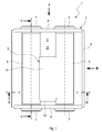
- Fig. 1 to 8 comprises a muffler 1, which can be used in a not shown here, at least partially twin-flow exhaust system of an internal combustion engine, which may be arranged in particular in a motor vehicle, a housing 2, the interior 3 encloses.
- the housing 2 consists, for example, of two frontally arranged bottoms 4 and of two half-shells 5, which surround the interior 3 laterally and in which the bottoms 4 are used for longitudinal limitation of the interior 3.
- Fig. 1 is the observer facing half-shell 5 omitted to allow insight into the interior 3 of the housing 2.
- the housing 2 has through the two half-shells 5 and through the two floors 4 an extremely simple and inexpensive construction. In principle, however, other designs for the housing 2 are conceivable.
- a one-piece tubular body can be used instead of the two half-shells 5.
- the muffler 1 also has exactly two or at least two exhaust pipes 6, which can be flowed through in parallel by the exhaust gas of the internal combustion engine and which are respectively guided through the inner space 3.
- the exhaust pipes 6 are guided through the two bottoms 4.
- the bottoms 4 have for this purpose annular collar 7, in which end portions of the exhaust pipes 6 are inserted.
- Each exhaust pipe 6 has within the housing 2 in the Fig. 4, 5 and 8th recognizable side opening 8. These side openings 8 are expediently arranged on the two exhaust pipes 6 so that they face each other. In particular, they are aligned with each other.
- the muffler 1 further includes a neck body 9, which serves to connect the two side openings 8 communicating with the interior 3 of the housing 2, in such a way that in this case a Helmholtz resonator is formed.
- the interior 3 of the housing 2 then serves as resonance volume of the Helmholtz resonator, while the neck body 9 encloses a neck volume 10 which defines the neck of the Helmholtz resonator.
- the neck body 9 has two sheet-shaped longitudinal walls 11, each at both exhaust pipes 6 abut.
- the longitudinal walls 11 are spaced from each other and define the aforementioned neck volume 10.
- the longitudinal walls 11 are arranged so that the side openings 8 open into the neck volume 10 between them.
- the two longitudinal walls 11 are open to the interior 3, that is to say to the resonant volume of the Helmholtz resonator designated below by 12.
- the neck body 9 is disposed entirely within the housing 2, in particular spaced from the housing 2 positioned.
- the neck body 9 also has a sheet-like transverse wall 13, which likewise forms a boundary of the neck volume 10. Accordingly, the neck volume 10 on the one hand of the side openings 8 is limited by the transverse wall 13 and on the other hand, the side openings 8 to the resonance volume 12 open. As a result, the neck volume 10 can be precisely determined, which simplifies the design of the Helmholtz resonator to a specific resonant frequency.
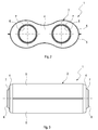
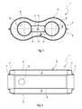
- the neck body 9 according to the 6 and 7 produce by means of a U-shaped sheet metal part 14, which may be formed in particular from a single piece of sheet metal.
- Legs 15 of the U-sheet metal part 14 form the longitudinal walls 11, while the two legs 15 interconnecting base 16 of the U-sheet metal part 14 forms the transverse wall 13.
- the Helmholtz resonator For the design of the Helmholtz resonator, it has proven to be favorable to arrange the two side openings 8 in the region of the transverse wall 13. As a result, virtually the entire neck volume 10 is available for generating a vibrating air mass.
- the neck body 9 can also be dispensed with the transverse wall 13, so that the neck volume 10 then on both sides of the side openings 8 to the resonance volume 12 is open.
- the neck body 9 then has two mutually opposite openings, with which it communicates with the resonance volume 12 and with the interior 3.
- the side openings 8 are located within the neck volume 10.
- the Helmholtz resonator acts uniformly for both exhaust pipes 6.
- the two exhaust pipes 6 are guided in a straight line and parallel to each other through the housing 2.
- the exhaust pipes 6 in the example between the plates 4 each have a constant cross section, which facilitates in particular the attachment of the neck body 9.
- other designs are conceivable here as well.
- the longitudinal walls 11 and the possibly existing transverse wall 13 are each "sheet-shaped" configured. This means in the present context, a substantially flat configuration of the walls, that is, the respective wall is dimensioned considerably larger in the longitudinal direction and in the width direction than in the thickness direction. Furthermore, the longitudinal walls 11 are each configured just here. Further, the investment areas in which the longitudinal walls 11 abut the exhaust pipes 6, designed here in a straight line, which is a gas-tight Connection between the longitudinal walls 11 and the exhaust pipes 6 simplified.
- the neck body 9 may be welded or soldered to the exhaust pipes 6.
- the bottoms 4 can be welded or soldered to the half-shells 5. Also, the two half-shells 5 can be attached to each other by welds or solder joints.
- the exhaust pipes 6 may be soldered or welded at their ends to the collar 7 of the bottom 4.
- the housing 2 may have a cross-section in the shape of a horizontal figure 8, that is, the half-shells 5 are each concave outwards.
- the stability of the housing 2 can be increased.
- this also the vibration behavior of the housing 2 can be influenced in the desired manner.
- this also allows the resonance volume 12 to be defined for the design of the Helmholtz resonator.
- the side openings 8 are provided with a circular cross-section. Fits to the transverse wall 13 in longitudinal section, such as in Fig. 7 clearly semicircular design. The radii of the side openings 8 and the transverse wall 3 are suitably coordinated with each other.
Landscapes
- Engineering & Computer Science (AREA)
- Chemical & Material Sciences (AREA)
- Combustion & Propulsion (AREA)
- Mechanical Engineering (AREA)
- General Engineering & Computer Science (AREA)
- Exhaust Silencers (AREA)
Claims (14)
- Silencieux pour un système d'échappement au moins partiellement à double flux d'un moteur à combustion interne, en particulier d'un véhicule automobile,- avec un carter (2) qui enferme un espace intérieur (3),- avec deux tubes de gaz d'échappement (6) pouvant être parcourus parallèlement par des gaz d'échappement, qui sont conduits respectivement à travers l'espace intérieur (3) et qui présentent respectivement à l'intérieur du carter (2) une ouverture latérale (8),- avec un corps de col (9) qui raccorde de façon communicante les deux ouvertures latérales (8) des tubes de gaz d'échappement (6) pour la formation d'un résonateur de Helmholtz avec l'espace intérieur (3) du carter (2) qui sert de volume de résonance (12),
caractérisé en ce que le corps de col (9) présente deux parois longitudinales (11) en forme de tôle qui sont respectivement adjacentes aux deux tubes de gaz d'échappement (6) et qui délimitent un volume de col (10) dans lequel débouchent les ouvertures latérales (8) des tubes de gaz d'échappement (6) et qui est ouvert vers le volume de résonance (12). - Silencieux selon la revendication 1,
caractérisé en ce que
le corps de col (9) présente une paroi transversale (13) en forme de tôle qui délimite le volume de col (10) d'un côté des ouvertures latérales (8) de telle sorte que en particulier le volume de col (10) n'est ouvert que de l'autre côté des ouvertures latérales (8) vers le volume de résonance (12). - Silencieux selon la revendication 2,
caractérisé en ce que
le corps de col (9) est formé d'une partie en tôle (14) en forme de U dont les branches (15) forment les parois longitudinales (11) et dont la base (16) forme la paroi transversale (13) et raccorde entre elles les deux branches (15). - Silencieux selon la revendication 3,
caractérisé en ce que
la partie en tôle (14) est formée d'une pièce en tôle unique. - Silencieux selon l'une des revendications 2 à 4,
caractérisé en ce que
les deux ouvertures latérales (8) sont disposées dans la zone de la paroi transversale (13). - Silencieux selon la revendication 1,
caractérisé en ce que
le volume de col (10) est ouvert des deux côtés des ouvertures latérales (8) vers le volume de résonance (12). - Silencieux selon l'une des revendications 1 à 6,
caractérisé en ce que
les ouvertures latérales (8) sont situées en face l'une de l'autre dans le volume de col (10). - Silencieux selon l'une des revendications 1 à 7,
caractérisé en ce que
les tubes de gaz d'échappement (6) sont conduits de façon rectiligne et parallèlement entre eux à travers le carter (2). - Silencieux selon l'une des revendications 1 à 8,
caractérisé en ce que
le carter (2) est constitué en construction monocoque. - Silencieux selon l'une des revendications 1 à 9,
caractérisé en ce que le corps de col (9) est disposé entre les deux tubes de gaz d'échappement (6). - Système de gaz d'échappement selon l'une des revendications 1 à 10,
caractérisé en ce que
des tronçons de paroi des deux tubes de gaz d'échappement (6) situés entre les parois longitudinales (11) forment des délimitations latérales du volume de col (10). - Silencieux selon l'une des revendications 1 à 11,
caractérisé en ce que
le corps de col (9) est disposé entièrement à l'intérieur du carter (2). - Silencieux selon l'une des revendications 1 à 12,
caractérisé en ce que
le corps de col (9) est positionné dans le carter (2) à distance de ce dernier. - Système de gaz d'échappement pour un moteur à combustion interne, en particulier d'un véhicule automobile, qui présente, dans un tronçon à double flux, un silencieux (1) selon l'une des revendications 1 à 13.
Applications Claiming Priority (1)
| Application Number | Priority Date | Filing Date | Title |
|---|---|---|---|
| DE102008027290A DE102008027290A1 (de) | 2008-06-06 | 2008-06-06 | Schalldämpfer für eine Abgasanlage |
Publications (2)
| Publication Number | Publication Date |
|---|---|
| EP2131015A1 EP2131015A1 (fr) | 2009-12-09 |
| EP2131015B1 true EP2131015B1 (fr) | 2015-10-21 |
Family
ID=40874753
Family Applications (1)
| Application Number | Title | Priority Date | Filing Date |
|---|---|---|---|
| EP09155257.0A Not-in-force EP2131015B1 (fr) | 2008-06-06 | 2009-03-16 | Silencieux pour un système d'échappement |
Country Status (3)
| Country | Link |
|---|---|
| US (1) | US7874401B2 (fr) |
| EP (1) | EP2131015B1 (fr) |
| DE (1) | DE102008027290A1 (fr) |
Families Citing this family (12)
| Publication number | Priority date | Publication date | Assignee | Title |
|---|---|---|---|---|
| US8191676B2 (en) | 2010-11-04 | 2012-06-05 | Ford Global Technologies, Llc | Resonator for a dual-flow exhaust system |
| DE102015211460A1 (de) * | 2015-06-22 | 2016-12-22 | Bayerische Motoren Werke Aktiengesellschaft | Abgasanlage |
| DE102018124198A1 (de) | 2017-10-05 | 2019-04-11 | Tenneco Automotive Operating Company Inc. | Akustisch abgestimmter Schalldämpfer |
| US11365658B2 (en) | 2017-10-05 | 2022-06-21 | Tenneco Automotive Operating Company Inc. | Acoustically tuned muffler |
| US11199116B2 (en) | 2017-12-13 | 2021-12-14 | Tenneco Automotive Operating Company Inc. | Acoustically tuned muffler |
| US11293664B2 (en) | 2018-03-06 | 2022-04-05 | Gulfstream Aerospace Corporation | Dual tube silencer for separate gas flows |
| DE102018106429A1 (de) | 2018-03-20 | 2019-09-26 | Eberspächer Exhaust Technology GmbH & Co. KG | Verfahren zur Herstellung eines Schalldämpfers |
| US11268429B2 (en) | 2019-01-17 | 2022-03-08 | Tenneco Automotive Operating Company Inc. | Diffusion surface alloyed metal exhaust component with inwardly turned edges |
| US11268430B2 (en) | 2019-01-17 | 2022-03-08 | Tenneco Automotive Operating Company Inc. | Diffusion surface alloyed metal exhaust component with welded edges |
| US10975743B1 (en) | 2020-03-13 | 2021-04-13 | Tenneco Automotive Operating Company Inc. | Vehicle exhaust component |
| CN115467733A (zh) * | 2022-09-15 | 2022-12-13 | 重庆市璧山区宗辉机械有限公司 | 一种摩托车分体式消声器 |
| US12116915B2 (en) | 2022-12-28 | 2024-10-15 | Tenneco Automotive Operating Company Inc. | Exhaust pipe bridge |
Family Cites Families (18)
| Publication number | Priority date | Publication date | Assignee | Title |
|---|---|---|---|---|
| US3114432A (en) * | 1961-08-21 | 1963-12-17 | Arvin Ind Inc | Sound attenuating gas conduit |
| DE1242414B (de) * | 1963-03-15 | 1967-06-15 | Daimler Benz Ag | Abgasanlage fuer Mehrzylinder-Brennkraftmaschinen |
| DE2706957C2 (de) * | 1977-02-18 | 1983-04-07 | Friedrich Boysen Gmbh & Co Kg, 7272 Altensteig | Abgasschalldämpfer |
| US4287962A (en) * | 1977-11-14 | 1981-09-08 | Industrial Acoustics Company | Packless silencer |
| DE2856889A1 (de) * | 1978-12-30 | 1980-11-20 | Zeuna Staerker Kg | Schalldaempfer in der abgasleitung eines verbrennungsmotors, insbesondere an einem kraftfahrzeug |
| JPS5893920A (ja) * | 1981-11-29 | 1983-06-03 | Nippon Radiator Co Ltd | 排気装置 |
| JPS5893919A (ja) * | 1981-11-29 | 1983-06-03 | Nippon Radiator Co Ltd | 排気装置 |
| US4487289A (en) * | 1982-03-01 | 1984-12-11 | Nelson Industries, Inc. | Exhaust muffler with protective shield |
| JPH068267Y2 (ja) * | 1987-01-28 | 1994-03-02 | カルソニック株式会社 | 制御型消音器の尾管構造 |
| US5009065A (en) * | 1988-08-15 | 1991-04-23 | Arvin Industries, Inc. | Tuned exhaust processor assembly |
| US4947645A (en) * | 1989-07-31 | 1990-08-14 | Pemberton Joseph H | Exhaust efficiency increasing apparatus |
| US5351481A (en) * | 1992-06-26 | 1994-10-04 | Flowmaster, Inc. | Muffler assembly with balanced chamber and method |
| US6470998B1 (en) * | 1999-10-26 | 2002-10-29 | James E. White | Modular muffler with end plate adaptors and spark arresters |
| US6889499B2 (en) * | 2001-05-16 | 2005-05-10 | Darryl C. Bassani | Internal combustion engine exhaust system |
| DE10300773A1 (de) * | 2003-01-11 | 2004-07-22 | Daimlerchrysler Ag | Abgasanlage für eine mehrzylindrige Brennkraftmaschine |
| DE10339811B4 (de) * | 2003-08-27 | 2005-09-22 | J. Eberspächer GmbH & Co. KG | Resonator zur Reduzierung von Luftschall |
| DE102005052619B4 (de) * | 2005-11-02 | 2012-10-18 | J. Eberspächer GmbH & Co. KG | Schalldämpfer für eine Abgasanlage |
| DE102007007600A1 (de) * | 2007-02-13 | 2008-08-14 | J. Eberspächer GmbH & Co. KG | Schalldämpfer für eine Abgasanlage |
-
2008
- 2008-06-06 DE DE102008027290A patent/DE102008027290A1/de not_active Withdrawn
-
2009
- 2009-03-16 EP EP09155257.0A patent/EP2131015B1/fr not_active Not-in-force
- 2009-05-19 US US12/468,230 patent/US7874401B2/en active Active
Also Published As
| Publication number | Publication date |
|---|---|
| US20090301807A1 (en) | 2009-12-10 |
| US7874401B2 (en) | 2011-01-25 |
| EP2131015A1 (fr) | 2009-12-09 |
| DE102008027290A1 (de) | 2009-12-10 |
Similar Documents
| Publication | Publication Date | Title |
|---|---|---|
| EP2131015B1 (fr) | Silencieux pour un système d'échappement | |
| DE69213709T2 (de) | Durch Stanzen hergestellter Schalldämpfer mit Reihenexpansionskammer und gebogen geformten Effektifströmungsröhren | |
| DE112018006353T5 (de) | Akustisch abgestimmter Schalldämpfer | |
| EP1467070A1 (fr) | Combinaison d'un traitement des gaz d'échappement et d'un silencieux implanté dans la ligne d'échappement d'un moteur à combustion interne | |
| EP2196640B1 (fr) | Silencieux | |
| EP2287451B1 (fr) | Système d'échappement et ensemble associé de connection à un actionneur | |
| DE112021003683T5 (de) | Plattenanordnung | |
| EP2446128B1 (fr) | Elément d isolation acoustique tubulaire | |
| DE102012204114B4 (de) | Schalldämpfer-Einheit | |
| EP3245396B1 (fr) | Silenciux pour vehicule | |
| EP1788216B1 (fr) | Liaison intermédiaire pour dispositif d'échappement | |
| DE10144015A1 (de) | Abgasanlage für mehrzylindrige Verbrennungsmotoren | |
| EP1375848B1 (fr) | Dispositif permettant de réduire les émissions sonores et méthode pour la réalisation d'un tel dispositif | |
| WO2012035163A1 (fr) | Unité de traitement de gaz d'échappement pour une conduite de recyclage de gaz d'échappement | |
| EP2407649A1 (fr) | Bride, bride de liaison et collecteur de gaz d'échappement | |
| DE102019101418A1 (de) | Schalldämpfer | |
| EP2607765A1 (fr) | Bride hybride | |
| DE102010039751A1 (de) | Abgasleitung für eine Brennkraftmaschine | |
| DE10359062A1 (de) | Haubenkrümmer | |
| DE102008021281A1 (de) | Abgasanlage für eine Brennkraftmaschine | |
| EP3265658B1 (fr) | Collecteur | |
| WO2009018950A1 (fr) | Enceinte pour silencieux | |
| WO2001051781A1 (fr) | Systeme d'echappement d'un moteur thermique | |
| DE102008021282A1 (de) | Abgasanlage für eine Brennkraftmaschine | |
| EP1524415A1 (fr) | Silencieux d'échappement |
Legal Events
| Date | Code | Title | Description |
|---|---|---|---|
| PUAI | Public reference made under article 153(3) epc to a published international application that has entered the european phase |
Free format text: ORIGINAL CODE: 0009012 |
|
| AK | Designated contracting states |
Kind code of ref document: A1 Designated state(s): AT BE BG CH CY CZ DE DK EE ES FI FR GB GR HR HU IE IS IT LI LT LU LV MC MK MT NL NO PL PT RO SE SI SK TR |
|
| AX | Request for extension of the european patent |
Extension state: AL BA RS |
|
| 17P | Request for examination filed |
Effective date: 20100609 |
|
| AKX | Designation fees paid |
Designated state(s): AT BE BG CH CY CZ DE DK EE ES FI FR GB GR HR HU IE IS IT LI LT LU LV MC MK MT NL NO PL PT RO SE SI SK TR |
|
| 17Q | First examination report despatched |
Effective date: 20120112 |
|
| RAP1 | Party data changed (applicant data changed or rights of an application transferred) |
Owner name: EBERSPAECHER EXHAUST TECHNOLOGY GMBH & CO. KG |
|
| GRAP | Despatch of communication of intention to grant a patent |
Free format text: ORIGINAL CODE: EPIDOSNIGR1 |
|
| RIC1 | Information provided on ipc code assigned before grant |
Ipc: F01N 1/02 20060101AFI20150702BHEP Ipc: F01N 13/00 20100101ALI20150702BHEP Ipc: F01N 1/00 20060101ALI20150702BHEP Ipc: F01N 13/04 20100101ALI20150702BHEP |
|
| INTG | Intention to grant announced |
Effective date: 20150720 |
|
| GRAS | Grant fee paid |
Free format text: ORIGINAL CODE: EPIDOSNIGR3 |
|
| GRAA | (expected) grant |
Free format text: ORIGINAL CODE: 0009210 |
|
| AK | Designated contracting states |
Kind code of ref document: B1 Designated state(s): AT BE BG CH CY CZ DE DK EE ES FI FR GB GR HR HU IE IS IT LI LT LU LV MC MK MT NL NO PL PT RO SE SI SK TR |
|
| REG | Reference to a national code |
Ref country code: GB Ref legal event code: FG4D Free format text: NOT ENGLISH Ref country code: NL Ref legal event code: MP Effective date: 20151021 |
|
| REG | Reference to a national code |
Ref country code: CH Ref legal event code: EP |
|
| REG | Reference to a national code |
Ref country code: AT Ref legal event code: REF Ref document number: 756751 Country of ref document: AT Kind code of ref document: T Effective date: 20151115 |
|
| REG | Reference to a national code |
Ref country code: IE Ref legal event code: FG4D Free format text: LANGUAGE OF EP DOCUMENT: GERMAN |
|
| REG | Reference to a national code |
Ref country code: DE Ref legal event code: R096 Ref document number: 502009011741 Country of ref document: DE |
|
| REG | Reference to a national code |
Ref country code: SE Ref legal event code: TRGR |
|
| REG | Reference to a national code |
Ref country code: LT Ref legal event code: MG4D |
|
| REG | Reference to a national code |
Ref country code: FR Ref legal event code: PLFP Year of fee payment: 8 |
|
| PG25 | Lapsed in a contracting state [announced via postgrant information from national office to epo] |
Ref country code: NO Free format text: LAPSE BECAUSE OF FAILURE TO SUBMIT A TRANSLATION OF THE DESCRIPTION OR TO PAY THE FEE WITHIN THE PRESCRIBED TIME-LIMIT Effective date: 20160121 Ref country code: HR Free format text: LAPSE BECAUSE OF FAILURE TO SUBMIT A TRANSLATION OF THE DESCRIPTION OR TO PAY THE FEE WITHIN THE PRESCRIBED TIME-LIMIT Effective date: 20151021 Ref country code: ES Free format text: LAPSE BECAUSE OF FAILURE TO SUBMIT A TRANSLATION OF THE DESCRIPTION OR TO PAY THE FEE WITHIN THE PRESCRIBED TIME-LIMIT Effective date: 20151021 Ref country code: NL Free format text: LAPSE BECAUSE OF FAILURE TO SUBMIT A TRANSLATION OF THE DESCRIPTION OR TO PAY THE FEE WITHIN THE PRESCRIBED TIME-LIMIT Effective date: 20151021 Ref country code: IS Free format text: LAPSE BECAUSE OF FAILURE TO SUBMIT A TRANSLATION OF THE DESCRIPTION OR TO PAY THE FEE WITHIN THE PRESCRIBED TIME-LIMIT Effective date: 20160221 Ref country code: LT Free format text: LAPSE BECAUSE OF FAILURE TO SUBMIT A TRANSLATION OF THE DESCRIPTION OR TO PAY THE FEE WITHIN THE PRESCRIBED TIME-LIMIT Effective date: 20151021 |
|
| PG25 | Lapsed in a contracting state [announced via postgrant information from national office to epo] |
Ref country code: PT Free format text: LAPSE BECAUSE OF FAILURE TO SUBMIT A TRANSLATION OF THE DESCRIPTION OR TO PAY THE FEE WITHIN THE PRESCRIBED TIME-LIMIT Effective date: 20160222 Ref country code: LV Free format text: LAPSE BECAUSE OF FAILURE TO SUBMIT A TRANSLATION OF THE DESCRIPTION OR TO PAY THE FEE WITHIN THE PRESCRIBED TIME-LIMIT Effective date: 20151021 Ref country code: GR Free format text: LAPSE BECAUSE OF FAILURE TO SUBMIT A TRANSLATION OF THE DESCRIPTION OR TO PAY THE FEE WITHIN THE PRESCRIBED TIME-LIMIT Effective date: 20160122 Ref country code: PL Free format text: LAPSE BECAUSE OF FAILURE TO SUBMIT A TRANSLATION OF THE DESCRIPTION OR TO PAY THE FEE WITHIN THE PRESCRIBED TIME-LIMIT Effective date: 20151021 Ref country code: FI Free format text: LAPSE BECAUSE OF FAILURE TO SUBMIT A TRANSLATION OF THE DESCRIPTION OR TO PAY THE FEE WITHIN THE PRESCRIBED TIME-LIMIT Effective date: 20151021 |
|
| REG | Reference to a national code |
Ref country code: DE Ref legal event code: R097 Ref document number: 502009011741 Country of ref document: DE |
|
| PG25 | Lapsed in a contracting state [announced via postgrant information from national office to epo] |
Ref country code: CZ Free format text: LAPSE BECAUSE OF FAILURE TO SUBMIT A TRANSLATION OF THE DESCRIPTION OR TO PAY THE FEE WITHIN THE PRESCRIBED TIME-LIMIT Effective date: 20151021 |
|
| PLBE | No opposition filed within time limit |
Free format text: ORIGINAL CODE: 0009261 |
|
| STAA | Information on the status of an ep patent application or granted ep patent |
Free format text: STATUS: NO OPPOSITION FILED WITHIN TIME LIMIT |
|
| PG25 | Lapsed in a contracting state [announced via postgrant information from national office to epo] |
Ref country code: RO Free format text: LAPSE BECAUSE OF FAILURE TO SUBMIT A TRANSLATION OF THE DESCRIPTION OR TO PAY THE FEE WITHIN THE PRESCRIBED TIME-LIMIT Effective date: 20151021 Ref country code: BE Free format text: LAPSE BECAUSE OF NON-PAYMENT OF DUE FEES Effective date: 20160331 Ref country code: DK Free format text: LAPSE BECAUSE OF FAILURE TO SUBMIT A TRANSLATION OF THE DESCRIPTION OR TO PAY THE FEE WITHIN THE PRESCRIBED TIME-LIMIT Effective date: 20151021 Ref country code: EE Free format text: LAPSE BECAUSE OF FAILURE TO SUBMIT A TRANSLATION OF THE DESCRIPTION OR TO PAY THE FEE WITHIN THE PRESCRIBED TIME-LIMIT Effective date: 20151021 Ref country code: SK Free format text: LAPSE BECAUSE OF FAILURE TO SUBMIT A TRANSLATION OF THE DESCRIPTION OR TO PAY THE FEE WITHIN THE PRESCRIBED TIME-LIMIT Effective date: 20151021 |
|
| 26N | No opposition filed |
Effective date: 20160722 |
|
| PG25 | Lapsed in a contracting state [announced via postgrant information from national office to epo] |
Ref country code: MC Free format text: LAPSE BECAUSE OF FAILURE TO SUBMIT A TRANSLATION OF THE DESCRIPTION OR TO PAY THE FEE WITHIN THE PRESCRIBED TIME-LIMIT Effective date: 20151021 Ref country code: LU Free format text: LAPSE BECAUSE OF FAILURE TO SUBMIT A TRANSLATION OF THE DESCRIPTION OR TO PAY THE FEE WITHIN THE PRESCRIBED TIME-LIMIT Effective date: 20160316 |
|
| REG | Reference to a national code |
Ref country code: CH Ref legal event code: PL |
|
| PG25 | Lapsed in a contracting state [announced via postgrant information from national office to epo] |
Ref country code: SI Free format text: LAPSE BECAUSE OF FAILURE TO SUBMIT A TRANSLATION OF THE DESCRIPTION OR TO PAY THE FEE WITHIN THE PRESCRIBED TIME-LIMIT Effective date: 20151021 |
|
| REG | Reference to a national code |
Ref country code: IE Ref legal event code: MM4A |
|
| PG25 | Lapsed in a contracting state [announced via postgrant information from national office to epo] |
Ref country code: LI Free format text: LAPSE BECAUSE OF NON-PAYMENT OF DUE FEES Effective date: 20160331 Ref country code: IE Free format text: LAPSE BECAUSE OF NON-PAYMENT OF DUE FEES Effective date: 20160316 Ref country code: CH Free format text: LAPSE BECAUSE OF NON-PAYMENT OF DUE FEES Effective date: 20160331 |
|
| REG | Reference to a national code |
Ref country code: FR Ref legal event code: PLFP Year of fee payment: 9 |
|
| REG | Reference to a national code |
Ref country code: AT Ref legal event code: MM01 Ref document number: 756751 Country of ref document: AT Kind code of ref document: T Effective date: 20160316 |
|
| PG25 | Lapsed in a contracting state [announced via postgrant information from national office to epo] |
Ref country code: AT Free format text: LAPSE BECAUSE OF NON-PAYMENT OF DUE FEES Effective date: 20160316 Ref country code: MT Free format text: LAPSE BECAUSE OF FAILURE TO SUBMIT A TRANSLATION OF THE DESCRIPTION OR TO PAY THE FEE WITHIN THE PRESCRIBED TIME-LIMIT Effective date: 20151021 |
|
| REG | Reference to a national code |
Ref country code: FR Ref legal event code: PLFP Year of fee payment: 10 |
|
| PG25 | Lapsed in a contracting state [announced via postgrant information from national office to epo] |
Ref country code: HU Free format text: LAPSE BECAUSE OF FAILURE TO SUBMIT A TRANSLATION OF THE DESCRIPTION OR TO PAY THE FEE WITHIN THE PRESCRIBED TIME-LIMIT; INVALID AB INITIO Effective date: 20090316 Ref country code: CY Free format text: LAPSE BECAUSE OF FAILURE TO SUBMIT A TRANSLATION OF THE DESCRIPTION OR TO PAY THE FEE WITHIN THE PRESCRIBED TIME-LIMIT Effective date: 20151021 |
|
| PGFP | Annual fee paid to national office [announced via postgrant information from national office to epo] |
Ref country code: IT Payment date: 20180322 Year of fee payment: 10 |
|
| PG25 | Lapsed in a contracting state [announced via postgrant information from national office to epo] |
Ref country code: TR Free format text: LAPSE BECAUSE OF FAILURE TO SUBMIT A TRANSLATION OF THE DESCRIPTION OR TO PAY THE FEE WITHIN THE PRESCRIBED TIME-LIMIT Effective date: 20151021 Ref country code: MK Free format text: LAPSE BECAUSE OF FAILURE TO SUBMIT A TRANSLATION OF THE DESCRIPTION OR TO PAY THE FEE WITHIN THE PRESCRIBED TIME-LIMIT Effective date: 20151021 |
|
| PG25 | Lapsed in a contracting state [announced via postgrant information from national office to epo] |
Ref country code: BG Free format text: LAPSE BECAUSE OF FAILURE TO SUBMIT A TRANSLATION OF THE DESCRIPTION OR TO PAY THE FEE WITHIN THE PRESCRIBED TIME-LIMIT Effective date: 20151021 |
|
| PG25 | Lapsed in a contracting state [announced via postgrant information from national office to epo] |
Ref country code: IT Free format text: LAPSE BECAUSE OF NON-PAYMENT OF DUE FEES Effective date: 20190316 |
|
| REG | Reference to a national code |
Ref country code: DE Ref legal event code: R081 Ref document number: 502009011741 Country of ref document: DE Owner name: PUREM GMBH, DE Free format text: FORMER OWNER: EBERSPAECHER EXHAUST TECHNOLOGY GMBH & CO. KG, 66539 NEUNKIRCHEN, DE |
|
| PGFP | Annual fee paid to national office [announced via postgrant information from national office to epo] |
Ref country code: SE Payment date: 20230315 Year of fee payment: 15 |
|
| PGFP | Annual fee paid to national office [announced via postgrant information from national office to epo] |
Ref country code: DE Payment date: 20240321 Year of fee payment: 16 Ref country code: GB Payment date: 20240322 Year of fee payment: 16 |
|
| PGFP | Annual fee paid to national office [announced via postgrant information from national office to epo] |
Ref country code: FR Payment date: 20240319 Year of fee payment: 16 |
|
| REG | Reference to a national code |
Ref country code: SE Ref legal event code: EUG |
|
| REG | Reference to a national code |
Ref country code: DE Ref legal event code: R119 Ref document number: 502009011741 Country of ref document: DE |
|
| PG25 | Lapsed in a contracting state [announced via postgrant information from national office to epo] |
Ref country code: SE Free format text: LAPSE BECAUSE OF NON-PAYMENT OF DUE FEES Effective date: 20240317 |
|
| GBPC | Gb: european patent ceased through non-payment of renewal fee |
Effective date: 20250316 |
|
| PG25 | Lapsed in a contracting state [announced via postgrant information from national office to epo] |
Ref country code: DE Free format text: LAPSE BECAUSE OF NON-PAYMENT OF DUE FEES Effective date: 20251001 |
|
| PG25 | Lapsed in a contracting state [announced via postgrant information from national office to epo] |
Ref country code: GB Free format text: LAPSE BECAUSE OF NON-PAYMENT OF DUE FEES Effective date: 20250316 |
|
| PG25 | Lapsed in a contracting state [announced via postgrant information from national office to epo] |
Ref country code: FR Free format text: LAPSE BECAUSE OF NON-PAYMENT OF DUE FEES Effective date: 20250331 |