EP2196688B1 - Mélangeur magnétique - Google Patents
Mélangeur magnétique Download PDFInfo
- Publication number
- EP2196688B1 EP2196688B1 EP10003314A EP10003314A EP2196688B1 EP 2196688 B1 EP2196688 B1 EP 2196688B1 EP 10003314 A EP10003314 A EP 10003314A EP 10003314 A EP10003314 A EP 10003314A EP 2196688 B1 EP2196688 B1 EP 2196688B1
- Authority
- EP
- European Patent Office
- Prior art keywords
- grooves
- bearing
- stirrer
- agitator
- rotor
- Prior art date
- Legal status (The legal status is an assumption and is not a legal conclusion. Google has not performed a legal analysis and makes no representation as to the accuracy of the status listed.)
- Active
Links
Images


Classifications
-
- F—MECHANICAL ENGINEERING; LIGHTING; HEATING; WEAPONS; BLASTING
- F16—ENGINEERING ELEMENTS AND UNITS; GENERAL MEASURES FOR PRODUCING AND MAINTAINING EFFECTIVE FUNCTIONING OF MACHINES OR INSTALLATIONS; THERMAL INSULATION IN GENERAL
- F16C—SHAFTS; FLEXIBLE SHAFTS; ELEMENTS OR CRANKSHAFT MECHANISMS; ROTARY BODIES OTHER THAN GEARING ELEMENTS; BEARINGS
- F16C33/00—Parts of bearings; Special methods for making bearings or parts thereof
- F16C33/02—Parts of sliding-contact bearings
- F16C33/04—Brasses; Bushes; Linings
- F16C33/06—Sliding surface mainly made of metal
- F16C33/10—Construction relative to lubrication
- F16C33/1025—Construction relative to lubrication with liquid, e.g. oil, as lubricant
- F16C33/106—Details of distribution or circulation inside the bearings, e.g. details of the bearing surfaces to affect flow or pressure of the liquid
- F16C33/1065—Grooves on a bearing surface for distributing or collecting the liquid
-
- B—PERFORMING OPERATIONS; TRANSPORTING
- B01—PHYSICAL OR CHEMICAL PROCESSES OR APPARATUS IN GENERAL
- B01F—MIXING, e.g. DISSOLVING, EMULSIFYING OR DISPERSING
- B01F27/00—Mixers with rotary stirring devices in fixed receptacles; Kneaders
- B01F27/80—Mixers with rotary stirring devices in fixed receptacles; Kneaders with stirrers rotating about a substantially vertical axis
- B01F27/808—Mixers with rotary stirring devices in fixed receptacles; Kneaders with stirrers rotating about a substantially vertical axis with stirrers driven from the bottom of the receptacle
-
- B—PERFORMING OPERATIONS; TRANSPORTING
- B01—PHYSICAL OR CHEMICAL PROCESSES OR APPARATUS IN GENERAL
- B01F—MIXING, e.g. DISSOLVING, EMULSIFYING OR DISPERSING
- B01F33/00—Other mixers; Mixing plants; Combinations of mixers
- B01F33/45—Magnetic mixers; Mixers with magnetically driven stirrers
- B01F33/453—Magnetic mixers; Mixers with magnetically driven stirrers using supported or suspended stirring elements
-
- F—MECHANICAL ENGINEERING; LIGHTING; HEATING; WEAPONS; BLASTING
- F16—ENGINEERING ELEMENTS AND UNITS; GENERAL MEASURES FOR PRODUCING AND MAINTAINING EFFECTIVE FUNCTIONING OF MACHINES OR INSTALLATIONS; THERMAL INSULATION IN GENERAL
- F16C—SHAFTS; FLEXIBLE SHAFTS; ELEMENTS OR CRANKSHAFT MECHANISMS; ROTARY BODIES OTHER THAN GEARING ELEMENTS; BEARINGS
- F16C17/00—Sliding-contact bearings for exclusively rotary movement
- F16C17/04—Sliding-contact bearings for exclusively rotary movement for axial load only
- F16C17/045—Sliding-contact bearings for exclusively rotary movement for axial load only with grooves in the bearing surface to generate hydrodynamic pressure, e.g. spiral groove thrust bearings
-
- F—MECHANICAL ENGINEERING; LIGHTING; HEATING; WEAPONS; BLASTING
- F16—ENGINEERING ELEMENTS AND UNITS; GENERAL MEASURES FOR PRODUCING AND MAINTAINING EFFECTIVE FUNCTIONING OF MACHINES OR INSTALLATIONS; THERMAL INSULATION IN GENERAL
- F16C—SHAFTS; FLEXIBLE SHAFTS; ELEMENTS OR CRANKSHAFT MECHANISMS; ROTARY BODIES OTHER THAN GEARING ELEMENTS; BEARINGS
- F16C17/00—Sliding-contact bearings for exclusively rotary movement
- F16C17/10—Sliding-contact bearings for exclusively rotary movement for both radial and axial load
-
- B—PERFORMING OPERATIONS; TRANSPORTING
- B01—PHYSICAL OR CHEMICAL PROCESSES OR APPARATUS IN GENERAL
- B01F—MIXING, e.g. DISSOLVING, EMULSIFYING OR DISPERSING
- B01F27/00—Mixers with rotary stirring devices in fixed receptacles; Kneaders
- B01F27/05—Stirrers
- B01F27/051—Stirrers characterised by their elements, materials or mechanical properties
- B01F27/053—Stirrers characterised by their elements, materials or mechanical properties characterised by their materials
-
- F—MECHANICAL ENGINEERING; LIGHTING; HEATING; WEAPONS; BLASTING
- F16—ENGINEERING ELEMENTS AND UNITS; GENERAL MEASURES FOR PRODUCING AND MAINTAINING EFFECTIVE FUNCTIONING OF MACHINES OR INSTALLATIONS; THERMAL INSULATION IN GENERAL
- F16C—SHAFTS; FLEXIBLE SHAFTS; ELEMENTS OR CRANKSHAFT MECHANISMS; ROTARY BODIES OTHER THAN GEARING ELEMENTS; BEARINGS
- F16C2240/00—Specified values or numerical ranges of parameters; Relations between them
- F16C2240/40—Linear dimensions, e.g. length, radius, thickness, gap
Definitions
- the invention relates to a magnetic stirrer for fluids, in particular for stirring sterile liquids, according to the preamble of patent claim 1.
- the stirring tools on the impeller head are designed as propellers. It can thereby generate an upward flow, so that an undesirable gas entry and foaming is avoided.
- the impeller head is provided with a bottom opening for receiving the split pot in a central cavity.
- the measure that between central cavity and the outer Surface is provided at least one connecting line, serves to constantly flush the inner cavity of the impeller with liquid, which facilitates the cleaning of the impeller.
- the object of the invention is therefore to provide a stirrer which does not have the disadvantages of the known devices. This object is achieved by a stirrer according to claim 1.
- the stirring head of the new stirrer comprises means for the hydrodynamic generation of a fluid film from the medium to be stirred for at least partially receiving the forces arising during stirring.
- the inventive stirrer 1 according to the embodiment of FIG. 1a is based on an impeller for use in the degradation of temperature and concentration gradients in aqueous solutions, as successfully produced and sold by the Applicant.
- a stirring head 2 preferably comprises two rings 3 and 4 arranged coaxially with one another, which are connected to one another via stirring elements 5.
- a magnetic outer rotor 6 is arranged in an upper bearing ring 4 is in the mixing head according to FIG. 1 a bearing shell 8 used.
- the bearing is a ceramic plain bearing.
- bearing shell 8 and bearing pin 9 cooperate in a known manner to ensure the radial and axial movement of the stirring head.
- bearing shell 8 and bearing pin 9 are provided at the lower end respectively with coaxial and coplanar disks 14, 15 which are vertical to the bearing axis A.
- the lower disc is designed as a stationary counter-disc 15 and the upper disc is formed as a rotor disc 14 radially and axially movable.
- An underside 16 of the rotor disk 14 is provided with hydrodynamically active structures, ie with grooves, preferably microgrooves.
- the liquid to be stirred is scooped into the grooves 20-24 and dammed up.
- the fluid pressure between the rotor disk 14 and the counter disk 15 becomes so high that the rotor disk 14 and with it the entire stirring head 2 in the axial direction is raised as it is in the Figure 1c is shown.
- the height of the resulting gap S between the rotor disk 14 and the counter disk 15 automatically adjusts as a function of the gap-opening forces and the gap-closing forces.
- the gap height is mainly dependent on the number and geometry of the grooves, the weight of the stirrer and the stirring members attached thereto, the speed at which it is stirred and the medium to be stirred.
- the illustrated embodiment of the FIG. 7 For example, depending on the speed, it stands out 0.05 to 1 mm.
- FIGS. 7a to 7b a further advantageous embodiment of the invention is shown in which, in contrast to the embodiment according to Fig. 1 the grooves do not extend over the entire surface of the bottom 16. In the center remains a circumferential web 18 stand, which rests on the top 17 of the counter-disc in the idle state. In the illustrated embodiment, the height of the groove decreases inwardly.
- the angle of inclination or tilt T is in the example shown at 7 °, the design and arrangement of the grooves is shown simplified. The tilt is preferably in the range of 0.1 to 10 ° and the inner web 18 is between 1 and 10 mm wide.
- the materials are chosen so that a clearance L of 0.02 to 0.5 mm - depending on the diameter and the sleeve length - is formed
- the means for the hydrodynamic generation of a fluid film are not formed as micro grooves but the underside
- the rotor disk is designed as a wavy face, as it is known for example from gas-lubricated mechanical seals of Flowserve, Irving, TX, USA.
- a frustoconical bearing can be used, in particular for smaller and lighter stirring heads, in which the axially and radially acting forces are generated and absorbed by only two surfaces.
- the means for hydrodynamic generation of the fluid film do not differ significantly from those described above.
- this is relevant only when starting and stopping the stirrer, otherwise an operating speed above the transition speed is selected.
- the transition speed also depends on the medium to be stirred, with high viscosity liquids reduce the transition speed and low viscosity increase it.
- FIG. 2 are in an exploded view in longitudinal section, the bearing 8, 9 and the means 14, 15 shown, which serve to relieve the bearing and to absorb the axial forces.
- bearing shell 8 and rotor disk 14 and corresponding bearing pin 9 and counter-disk 15 are each made in one piece.
- the rotor disk 14 and the counter-disk 15 are made of the same high-quality materials as the bearings, the friction does not occur when starting and stopping the stirrer Problem. As soon as the speed of the stirrer for the hydrodynamic generation of the fluid film from the medium to be stirred sufficient, this separates the two surfaces 16, 17 against the weight of the stirring head 2 and against the axially downwardly directed forces generated during stirring.
- a stirring head as in the FIG.
- stirrer 5 is outlined, carries depending on the application more on the shaft 19 superimposed stirrers and can weigh up to 50 kg. In order to avoid lateral tilting, these stirrers have hitherto had to be stabilized with an upper bearing 26. The upper storage dissolves However, the weight problem not because the stirring head still rests with the full weight on the gap pot.
- the present invention makes it particularly advantageous to relieve the bearing and to minimize the undesirable abrasion.
- Preferred materials for the production of bearing shell, rotor disk, bearing journal and counter disk are silicon carbide (SiC), zirconium oxide (ZrO 2 ), aluminum oxide (Al 2 O 3 ), polyether ether ketone (PEEK), polyvinylidene fluoride (PVDF), Teflon® (high-performance plastics perfluoroalkoxy copolymer ( PFA) and polytetrafluoroethylene (PTFE)), Teflon® with glass or carbon fiber, carbon or graphite
- SiC silicon carbide
- ZrO 2 zirconium oxide
- Al 2 O 3 aluminum oxide
- PEEK polyether ether ketone
- PVDF polyvinylidene fluoride
- Teflon® high-performance plastics perfluoroalkoxy copolymer
- PTFE polytetrafluoroethylene
- the rotor disk and the counter disk, respectively bearing shell and bearing journal are not made of the same material in order to minimize the tendency to seize.
- a preferred combination of materials is SiC and ZrO 2 .
- bearing shell / rotor disc and bearing pin / counter-disc are each shown in one piece, since the products shown are designed for use in sterile technology. In this area, all reusable components that are in contact with the sterile solutions must be able to be cleaned simply and with the utmost thoroughness, which clearly speaks in favor of the one-piece design of bearing shell / rotor disc and bearing journal / counter-disc. Since the seal between the bearing shell and rotor disc and bearing pin and counter-disc on the one hand consuming and on the other hand encounters the users in the sterile technology to rejection is set for commercial reasons on the one-piece construction. For applications in which it is not necessary to work sterile, two-piece bearing shell / rotor disk and bearing journal / counter disk come into consideration, whereby more material combinations are possible and the production costs can be reduced in a conventional seal.
- the stirrers according to the invention can be operated at substantially higher rotational speeds than was possible with known magnetic stirrers.
- Rotor-stator agitators which can be operated at up to 3000 rpm, are now possible.
- FIG. 6 is such a mixer for dispersing shown, with which the desired high peripheral speed can be realized.
- FIG. 1 In the FIG. 1 is the container bottom 11, in which a basal flange 12 of the split pot 10 is welded, only indicated.
- the illustrated example is a floor magnetic stirrer, as used, for example, in bioreactors. From the drive, only the driving magnet, that is to say an internal rotor 7, and the upper portions of a drive shaft 13, on which the internal rotor 7 is seated, are shown ,
- the outer rotor is preferably encapsulated in the drive ring and does not come into contact with the liquids to be stirred.
- the means for hydrodynamic generation of the fluid film comprise a portion of the top surface of the flange formed as a counter-disc and a portion of the underside of the drive ring formed as a rotor disc.
- the drive ring with its portion carrying the hydrodynamically active means lies on the region of the flange formed as a counter-disc.
- a fluid film forms between the rotor disk and the counter disk and the stirring head is raised.
- the effective surfaces of the rotor and the counter disk and their diameter can be greatly increased, so that even large and very heavy stirring elements can be easily lifted and stabilized during operation.
- the actual bearing of such a stirrer must have a corresponding axial clearance, wherein the radial portions 14, 15 as shown in the figures can be completely dispensed with.
- the area designated as the counter pane of the flange or the container bottom is preferably interrupted in further advantageous embodiments in the radial direction, in order to ensure a good circulation of the medium to be stirred. These interruptions allow simpler groove shapes, since the fluid no longer needs to be conveyed from the periphery to the center, but can be scooped into the grooves in the region of the interruptions over the entire width of the rotor disk.
- the stirrer according to the invention are optimized for installation in disposable containers.
- Stirrer and containment shell are preferably made of plastic, so that they can be easily disposed of together with the disposable container after a single use.
- Such disposable containers are used both to reduce costs for the plant parts per se, such as reactors, fermenters, mixing and transport containers, while avoiding their time and thus costly cleaning.
- Such disposable containers which are easy to dispose of after use, are known, for example, from Newport Bio Systems Inc. of Anderson CA, USA, and are advertised with the slogan "Biobags for biotech a cleanroom in a bag".
- These flexible disposable packages or biobags are made, for example, from class VI polyethylene with volumes between 0.5 and 2500 liters.
- the structure of the flexible container wall is different, with mostly multilayer coextruded films (LLDPE, EVOH, LLDPE / EVA, NYLON (PVdC coated)) being selected.
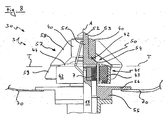
- FIG. 8 an embodiment of a stirrer 30 is shown, which is installed in such a disposable container 70.
- a split shell 50 made of plastic comprises a basal flange 12 ', which is provided for connection to a lower container wall 70 with a radial flange 56.
- the container wall 70 is preferably glued or welded to the flange 56, or flanged or clamped by suitable means.
- the container wall 70 may be attached in other, not shown in the figures embodiments, also directly on the basal flange 55 or the split pot 50, in all cases, a tight connection must be ensured.
- the split pot 50 For receiving the drive shaft 13 with the inner rotor 7, the split pot 50 in turn has a corresponding receiving space, so that the inner rotor 7 and a corresponding outer rotor 43 can be brought into a coplanar position to be able to couple the force of the inner rotor radially into the outer rotor can.
- the outer rotor 6 is completely encapsulated in the driving ring 41 made of plastic and instead of the above-described separate bearing shell and bearing ring act correspondingly formed areas of a bearing ring 40 with an axial bearing pin 51 of the containment shell together.
- the stirring heads 31 and the gap pots 50 are constructed so that they can be manufactured in injection molding technology.
- a separating plane can be laid through the stirring head 31 so that it is subdivided into two parts which can be removed from an injection mold without difficulty.
- the drive ring 41 is divided into a lower portion 42 having a receiving space for the outer rotor 43 and an upper cover 44.
- the cover 44 is preferably integrally formed on at least one of the stirrers 57, so that only two plastic components must be handled for assembly.
- the external rotor 43 which may comprise one or more individual magnets with a corresponding polarity, can be placed in the receiving space and a manufacturing-technically more complicated overmolding of the magnet or magnets in the mold is dispensed with.
- the upper portion 44 is placed both parts are connected together.
- the lid 44 is not connected to the stirring elements, but via a hinge to the lower part 42, so that it must be pivoted after inserting the magnets for assembly only to the hinge.
- Lid and base can each be welded together, for example, in the closed state, glued or be clamped, flanged or screwed by suitable means.
- the stirring members 57 of the embodiment of FIG. 8 can not inject undercut and thus have in this type of production preferably also on an upper 58 and a lower portion 59, which are preferably approximately in the region of the parting plane, for example, not shown in the drawing, male and female parts of a connector connected to each other.
- the stirrers 57 can, for example, act directly on the cover 44, which transmits the torque of the lower part and outer rotor 43 to the stirring elements.
- the interior of the disposable containers is no longer accessible after production.
- the containers are stored in a closed state and folded together in a space-saving manner and / or transported to their place of use. So that the stirring head 31 can not be detached from the split pot 50 during transport and during use, it is preferably caught on the bearing journal 51, as shown in FIG FIG. 8
- the stirring head 31 is mounted radially and axially movable with desired clearance. In the idle state, the stirring head 31 is located with a, corresponding to the underside of the rotor disk, underside 42 of the bearing ring 40 on one, the top of the opposite disc corresponding mating surface 54 of the split pot 50.
- the stirring head 31 From reaching the transitional speed, the stirring head 31 in turn lifts off from the containment shell, wherein the axial displacement mobility is limited upwards by a button 52 arranged at the upper end of the axis 51.
- a radially encircling bead 53 prevents the agitating head 31 from falling from the bearing journal 51 during transport or operation.
- the diameter of the knob 52 in the region of the bead 53 is preferably just so much larger than the inner diameter of the central opening in the bearing ring 40, that the stirring head 31 is held securely on the axis 51, but he simply in production over from above Knob 52 on the axle, respectively, the journals 51 poke.
- embodiments bearing ring 40 and axis 51 are not manufactured in one piece but comprise a separate bearing shell, respectively, a separate Journals.
- the hydrodynamically active agents can be designed in the disposable stirrer 30 substantially analogous to those of the above-described metal stirrer, the preferred injection molding production brings enormous benefits for the manufacturing cost.
- the plastic components of the stirrer 30 for disposable containers are preferably made of HDPE, since this Material can be well processed by injection molding and can be welded to the container wall 70.
- the types of motors that can be used with the stirrers according to the invention in the drive for are known from the prior art: DC drives, AC drives, if necessary, in explosion-proof design (ATEX), speed-controlled motors with external or integrated frequency converter and pneumatic actuators, each combined with a suitable transmission variant.
- ATEX explosion-proof design
- An optional quick release allows for easy disassembly of the motor in case the container is to be autoclaved.
- the drive comprises a lowering device for the drive shaft with the driving magnet 7. Especially with high-torque agitators this facilitates the safe and simple removal of the stirring head 2 even with strong magnetic fields.
- the transferable torques are in the inventive stirrers in the range of 30 Ncm to 300Nm.
Landscapes
- General Engineering & Computer Science (AREA)
- Engineering & Computer Science (AREA)
- Mechanical Engineering (AREA)
- Chemical & Material Sciences (AREA)
- Chemical Kinetics & Catalysis (AREA)
- Fluid Mechanics (AREA)
- Physics & Mathematics (AREA)
- Oil, Petroleum & Natural Gas (AREA)
- Mixers Of The Rotary Stirring Type (AREA)
- Mixers With Rotating Receptacles And Mixers With Vibration Mechanisms (AREA)
- Accessories For Mixers (AREA)
- Developing Agents For Electrophotography (AREA)
- Liquid Crystal (AREA)
- Valve Device For Special Equipments (AREA)
Claims (6)
- Agitateur pour fluide (1,30) sans contact, pouvant être entraîné inductivement ou magnétiquement, notamment pour agiter des liquides stériles, avec les caractéristiques suivantes :un pot de confinement (10,0),une tête d'agitateur (2,31) mobile en rotation sur celui-ci,caractérisé parla tête d'agitateur (2) est positionnée de manière mobile radialement et axialement par un coussinet de palier (8) sur un tourillon (9) du pot de confinement (10,50),un disque de rotor (14) disposé sur l'extrémité inférieure du coussinet de palier (8) perpendiculairement à l'axe de palier A pour la génération hydrodynamique d'un film fluide à partir du milieu à agiter en coopération avec un contre-plateau (15) disposé de manière coaxiale et coplanaire sur l'extrémité inférieure du tourillon (9), dans lequel le disque de rotor (14) est pourvu de rainures (20-24) sur sa face inférieure (16) tournée vers le contre-plateau (15).
- Agitateur selon la revendication 1, dans lequel les rainures sont sélectionnées en vue du fonctionnement dans une direction de rotation parmi le groupe : rainure en V, rainure en spirale et en vue du fonctionnement dans les deux directions de rotation parmi le groupe : rainure en T, rainure en U, rainure en sapin.
- Agitateur (1) selon la revendication 1, dans lequel la hauteur des rainures va en diminuant vers l'intérieur.
- Agitateur (1) selon la revendication 3, dans lequel la hauteur des rainures va en diminuant vers l'intérieur avec un angle d'inclinaison de 5° à 10°.
- Agitateur (1) selon la revendication 3, dans lequel la hauteur des rainures va en diminuant vers l'intérieur avec un angle d'inclinaison de 7°.
- Agitateur (1) selon la revendication 1, dans lequel le coussinet de palier (8) et le disque de rotor (14) ainsi que la tourillon (9) et le contre-plateau (15) sont respectivement fabriqués en un seul tenant.
Applications Claiming Priority (2)
| Application Number | Priority Date | Filing Date | Title |
|---|---|---|---|
| CH13032005 | 2005-07-29 | ||
| EP06405312A EP1748201B1 (fr) | 2005-07-29 | 2006-07-18 | Mélangeur magnétique |
Related Parent Applications (1)
| Application Number | Title | Priority Date | Filing Date |
|---|---|---|---|
| EP06405312.7 Division | 2006-07-18 |
Publications (3)
| Publication Number | Publication Date |
|---|---|
| EP2196688A2 EP2196688A2 (fr) | 2010-06-16 |
| EP2196688A3 EP2196688A3 (fr) | 2010-07-07 |
| EP2196688B1 true EP2196688B1 (fr) | 2011-05-25 |
Family
ID=37198854
Family Applications (2)
| Application Number | Title | Priority Date | Filing Date |
|---|---|---|---|
| EP06405312A Active EP1748201B1 (fr) | 2005-07-29 | 2006-07-18 | Mélangeur magnétique |
| EP10003314A Active EP2196688B1 (fr) | 2005-07-29 | 2006-07-18 | Mélangeur magnétique |
Family Applications Before (1)
| Application Number | Title | Priority Date | Filing Date |
|---|---|---|---|
| EP06405312A Active EP1748201B1 (fr) | 2005-07-29 | 2006-07-18 | Mélangeur magnétique |
Country Status (4)
| Country | Link |
|---|---|
| US (1) | US8128277B2 (fr) |
| EP (2) | EP1748201B1 (fr) |
| AT (2) | ATE493588T1 (fr) |
| DE (1) | DE502006008592D1 (fr) |
Families Citing this family (29)
| Publication number | Priority date | Publication date | Assignee | Title |
|---|---|---|---|---|
| US8870446B2 (en) | 2006-06-21 | 2014-10-28 | Spinomix S.A. | Device and method for manipulating and mixing magnetic particles in a liquid medium |
| US8585279B2 (en) * | 2006-06-21 | 2013-11-19 | Spinomix S.A. | Device and method for manipulating and mixing magnetic particles in a liquid medium |
| US8999732B2 (en) * | 2006-06-21 | 2015-04-07 | Spinomix, S.A. | Method for manipulating magnetic particles in a liquid medium |
| US7520657B2 (en) * | 2006-07-14 | 2009-04-21 | Sigma-Aldrich Co. | Magnetic stirrer |
| US20080151686A1 (en) * | 2006-11-14 | 2008-06-26 | Charles Meadows | Mixing bag for use with nonabrasive stir bar |
| EP2114554A1 (fr) * | 2007-02-21 | 2009-11-11 | Levtech Inc. | Roulement à rouleaux pour élément agitateur de fluide et récipient associé |
| DE102007054233B4 (de) * | 2007-11-12 | 2010-06-10 | Ika-Werke Gmbh & Co. Kg | Vorrichtung zum Dispergieren oder Homogenisieren |
| FR2943560B1 (fr) * | 2009-03-24 | 2011-05-27 | Jean Pascal Zambaux | Bioreacteur jetable et systeme d'agitation a usage unique |
| JP5710206B2 (ja) * | 2010-10-22 | 2015-04-30 | 株式会社環境技研 | 水素溶解水製造装置 |
| DE102011018626A1 (de) * | 2011-04-21 | 2012-10-25 | Minebea Co., Ltd. | Lagerrillenstruktur für eine Lagerfläche eines fluiddynamischen Lagers |
| KR101115420B1 (ko) * | 2011-10-11 | 2012-02-28 | (주) 오스타테크 | 액상물 혼합 용해촉진장치 |
| US9339026B2 (en) * | 2012-06-14 | 2016-05-17 | Therapeutic Proteins International, LLC | Pneumatically agitated and aerated single-use bioreactor |
| KR102103338B1 (ko) | 2013-04-19 | 2020-05-29 | 이엠디 밀리포어 코포레이션 | 일회용 바이오리액터 내의 신축성 필름 배플 |
| DE102013104788A1 (de) * | 2013-05-08 | 2014-11-13 | Liquitec Ag | Magnetrührwerk |
| US11944946B2 (en) | 2013-06-28 | 2024-04-02 | Saint-Gobain Performance Plastics Corporation | Mixing assemblies including magnetic impellers |
| RU2016102091A (ru) | 2013-06-28 | 2017-07-27 | Сен-Гобен Перфоманс Пластикс Корпорейшн | Смешивающие устройства, содержащие магнитные импеллеры |
| EP3241608B1 (fr) * | 2016-05-02 | 2020-04-08 | Levitronix GmbH | Dispositif de melange et dispositif jetable pour un tel dispositif de melange |
| AT518668B1 (de) * | 2017-01-25 | 2017-12-15 | Zeta Biopharma Gmbh | Rührwerk für einen Rührbehälter |
| AT520184B1 (de) * | 2017-09-18 | 2019-02-15 | Zeta Biopharma Gmbh | Rührkopf mit Identifikationsvorrichtung |
| CN108180884A (zh) * | 2017-12-20 | 2018-06-19 | 北京华航无线电测量研究所 | 一种管道内变形测量装置 |
| FR3079364A1 (fr) * | 2018-03-26 | 2019-09-27 | Damien Duclos | Dispositif d’entrainement electromagnetique d’une helice d’agitation avec une etancheite dynamique parfaite. |
| EP3659700B1 (fr) | 2018-11-29 | 2022-04-20 | Alfa Laval Corporate AB | Mélangeur de liquide à couplage magnétique |
| US11065589B2 (en) | 2018-12-10 | 2021-07-20 | Pall Corporation | Radially driven agitator |
| KR102296384B1 (ko) * | 2019-09-18 | 2021-09-01 | 세드나이엔지(주) | 마그네틱 교반기용 임펠러 및 이를 포함하는 마그네틱 교반기 |
| CN111013469B (zh) * | 2019-12-16 | 2022-02-25 | 河北奥格流体设备有限公司 | 无轴套全悬浮磁力搅拌器 |
| DE102020129567A1 (de) | 2020-11-10 | 2022-05-12 | Schaeffler Technologies AG & Co. KG | Winkelscheibe für eine Gleit- oder Wälzlageranordnung |
| CN117980061A (zh) * | 2021-09-15 | 2024-05-03 | 萨尼舒尔股份有限公司 | 小容量磁力混合系统 |
| KR102529757B1 (ko) * | 2023-03-03 | 2023-05-09 | 정승호 | 모터직결식 자동 자력이탈장치 |
| CN116956495B (zh) * | 2023-08-03 | 2024-01-26 | 浙江长城搅拌设备股份有限公司 | 一种底入式磁力搅拌装置的设计方法 |
Family Cites Families (24)
| Publication number | Priority date | Publication date | Assignee | Title |
|---|---|---|---|---|
| US1420773A (en) * | 1921-12-22 | 1922-06-27 | Magnetic Drink Mixer Company | Electrical drink mixer |
| JPH0615025B2 (ja) * | 1986-05-23 | 1994-03-02 | 株式会社荏原製作所 | 撹拌子 |
| US4993841A (en) | 1987-02-05 | 1991-02-19 | Steridose Systems Ab | Magnetic impeller means for a mixing vessel |
| KR0138254B1 (ko) * | 1989-03-10 | 1998-04-27 | 니시오카 시게루 | 교반장치 |
| SE463750B (sv) | 1989-05-26 | 1991-01-21 | Steridose Systems Ab | Omroerare foer aseptiska aendamaal, vilken aer vridbar i en foerutbestaemd rotationsriktning genom induktiva drivorgan inuti en tank |
| CN1017692B (zh) * | 1990-02-26 | 1992-08-05 | 华南理工大学 | 电磁动态塑化挤出方法及设备 |
| KR920702486A (ko) * | 1990-06-14 | 1992-09-04 | 기이찌 히라따 | 에멀젼 제조장치와 그 연소 시스템 |
| US5399074A (en) * | 1992-09-04 | 1995-03-21 | Kyocera Corporation | Motor driven sealless blood pump |
| DE4232934C2 (de) | 1992-10-01 | 1996-03-28 | Mavag Verfahrenstech Ag | Doppel-Impeller zum Rühren von sterilen Flüssigkeiten |
| DE4232936C2 (de) * | 1992-10-01 | 1996-03-28 | Mavag Verfahrenstech Ag | Impeller zum Rühren von sterilen Flüssigkeiten |
| JP2596881B2 (ja) * | 1992-12-24 | 1997-04-02 | 株式会社荏原製作所 | マグネット式ノンシール撹拌機 |
| FR2788995B1 (fr) * | 1999-01-28 | 2001-04-06 | Mixel | Agitateur a entrainement magnetique et procede du reglage du couple limite de transmission d'effort d'un tel agitateur |
| FR2779361B1 (fr) * | 1998-06-05 | 2000-07-28 | Mixel | Agitateur a entrainement magnetique |
| US6443715B1 (en) * | 1999-11-19 | 2002-09-03 | Campbell Hausfeld/Scott Fetzer Company | Pump impeller |
| US7762716B2 (en) * | 2000-10-09 | 2010-07-27 | Levtech, Inc. | Mixing vessel with a fluid-agitating element supported by a roller bearing |
| WO2003028869A2 (fr) * | 2001-10-03 | 2003-04-10 | Levtech, Inc. | Recipient ou sac de melange possedant un receptacle pour un element agitateur de fluide |
| US8182137B2 (en) * | 2000-10-09 | 2012-05-22 | Atmi Packaging, Inc. | Mixing bag or vessel with a fluid-agitating element |
| US6464387B1 (en) * | 2000-12-05 | 2002-10-15 | Fred Stogsdill | Magnetic stirrer having a channel for fluid |
| ATE272439T1 (de) * | 2001-02-22 | 2004-08-15 | Medic Tools Ag | Vorrichtung zum mischen und homogenisieren von materialien in einem labortestgefäss mit einem rührelement |
| US6881033B2 (en) * | 2002-09-30 | 2005-04-19 | Fisher & Paykel Healthcare Limited | Impeller |
| US6854877B2 (en) * | 2002-10-16 | 2005-02-15 | Aseptic Controls Investment Co. | Mixer for aseptic liquids |
| US20080008028A1 (en) * | 2004-06-23 | 2008-01-10 | Levtech, Inc. | Mixing vessel alignment systems, devices, and related methods |
| JP4508968B2 (ja) * | 2005-07-27 | 2010-07-21 | 有限会社Os技研 | 撹拌装置及びこれを用いた監視システム |
| US7748893B2 (en) * | 2006-02-14 | 2010-07-06 | Bel-Art Products, Inc. | Magnetic stirring arrangement |
-
2006
- 2006-07-18 AT AT06405312T patent/ATE493588T1/de active
- 2006-07-18 DE DE502006008592T patent/DE502006008592D1/de active Active
- 2006-07-18 AT AT10003314T patent/ATE511031T1/de active
- 2006-07-18 EP EP06405312A patent/EP1748201B1/fr active Active
- 2006-07-18 EP EP10003314A patent/EP2196688B1/fr active Active
- 2006-07-28 US US11/495,141 patent/US8128277B2/en not_active Expired - Fee Related
Also Published As
| Publication number | Publication date |
|---|---|
| ATE493588T1 (de) | 2011-01-15 |
| ATE511031T1 (de) | 2011-06-15 |
| EP1748201A3 (fr) | 2007-10-03 |
| US8128277B2 (en) | 2012-03-06 |
| US20070036027A1 (en) | 2007-02-15 |
| EP2196688A3 (fr) | 2010-07-07 |
| EP1748201B1 (fr) | 2010-12-29 |
| DE502006008592D1 (de) | 2011-02-10 |
| EP1748201A2 (fr) | 2007-01-31 |
| EP2196688A2 (fr) | 2010-06-16 |
Similar Documents
| Publication | Publication Date | Title |
|---|---|---|
| EP2196688B1 (fr) | Mélangeur magnétique | |
| DE112006000814B4 (de) | Ultrareiner magnetischer Mischer | |
| EP2285478B1 (fr) | Système de mélange | |
| EP0590473B1 (fr) | Agitateur pour remuer des liquides stériles | |
| US5397178A (en) | Screw container as dispenser for pharmaceutical and/or cosmetic ointments produced with a stirrer | |
| US5470152A (en) | Radially mounted magnetic coupling | |
| EP1825907B1 (fr) | Dispositif d'homogénéisation | |
| DE102008010427B4 (de) | Bioreaktor | |
| EP0344532A2 (fr) | Dispositif d'étanchéification du palier d'un axe tournant avec son équipement moteur | |
| EP1940539B1 (fr) | Contenant jetable a agitateur | |
| EP0599010A1 (fr) | Agitateur double pour remuer des liquides steriles | |
| EP0590472B1 (fr) | Mélangeur magnétique | |
| CN210251914U (zh) | 外转子高剪切分散乳化混合装置 | |
| EP3471868A1 (fr) | Mélangeur vibrant pour mélanger des liquides, des liquides avec des gaz ou des solides dans des récipients à usage unique | |
| EP1470856B1 (fr) | Agitateur pour mélanger, homogénéiser et disperser | |
| EP0137606A2 (fr) | Réservoir de mélange et de conservation de suspensions et solutions stériles | |
| US4813786A (en) | Fluid mixing unit | |
| JP5629892B2 (ja) | 高圧均質化装置の噴射弁、および噴射弁ユニット | |
| US20060099028A1 (en) | Coupling assembly and method for connecting and disconnecting a shaft assembly | |
| US20020118597A1 (en) | Mixing head with axial flow | |
| CN207996575U (zh) | 一种罐盖自动提升的双向搅拌高剪切乳化罐 | |
| DE102017007557A1 (de) | Mischvorrichtung und Verfahren zum Betreiben einer Mischvorrichtung | |
| CN219722727U (zh) | 一种混合装置 | |
| CN214345889U (zh) | 一种防黏壁复合搅拌式化妆品乳化设备 | |
| CN208926051U (zh) | 食物料理机 |
Legal Events
| Date | Code | Title | Description |
|---|---|---|---|
| PUAI | Public reference made under article 153(3) epc to a published international application that has entered the european phase |
Free format text: ORIGINAL CODE: 0009012 |
|
| PUAL | Search report despatched |
Free format text: ORIGINAL CODE: 0009013 |
|
| AC | Divisional application: reference to earlier application |
Ref document number: 1748201 Country of ref document: EP Kind code of ref document: P |
|
| AK | Designated contracting states |
Kind code of ref document: A2 Designated state(s): AT BE BG CH CY CZ DE DK EE ES FI FR GB GR HR HU IE IS IT LI LT LU LV MC MK MT NL NO PL PT RO SE SI SK SM TR |
|
| AK | Designated contracting states |
Kind code of ref document: A3 Designated state(s): AT BE BG CH CY CZ DE DK EE ES FI FR GB GR HR HU IE IS IT LI LT LU LV MC MK MT NL NO PL PT RO SE SI SK SM TR |
|
| RAP1 | Party data changed (applicant data changed or rights of an application transferred) |
Owner name: ZETA BIOPHARMA GMBH |
|
| 17P | Request for examination filed |
Effective date: 20100730 |
|
| RIC1 | Information provided on ipc code assigned before grant |
Ipc: B01F 7/16 20060101ALI20101104BHEP Ipc: F16C 33/10 20060101AFI20101104BHEP Ipc: B01F 13/08 20060101ALI20101104BHEP |
|
| GRAP | Despatch of communication of intention to grant a patent |
Free format text: ORIGINAL CODE: EPIDOSNIGR1 |
|
| RBV | Designated contracting states (corrected) |
Designated state(s): AT BE BG CH CY CZ DE DK EE ES FI FR GB GR HU IE IS IT LI LT LU LV MC NL PL PT RO SE SI SK TR |
|
| GRAS | Grant fee paid |
Free format text: ORIGINAL CODE: EPIDOSNIGR3 |
|
| GRAA | (expected) grant |
Free format text: ORIGINAL CODE: 0009210 |
|
| AC | Divisional application: reference to earlier application |
Ref document number: 1748201 Country of ref document: EP Kind code of ref document: P |
|
| AK | Designated contracting states |
Kind code of ref document: B1 Designated state(s): AT BE BG CH CY CZ DE DK EE ES FI FR GB GR HU IE IS IT LI LT LU LV MC NL PL PT RO SE SI SK TR |
|
| REG | Reference to a national code |
Ref country code: GB Ref legal event code: FG4D Free format text: NOT ENGLISH |
|
| REG | Reference to a national code |
Ref country code: CH Ref legal event code: EP |
|
| REG | Reference to a national code |
Ref country code: IE Ref legal event code: FG4D Free format text: LANGUAGE OF EP DOCUMENT: GERMAN |
|
| REG | Reference to a national code |
Ref country code: DE Ref legal event code: R096 Ref document number: 502006009589 Country of ref document: DE Effective date: 20110707 |
|
| REG | Reference to a national code |
Ref country code: CH Ref legal event code: NV Representative=s name: HANS RUDOLF GACHNANG PATENTANWALT |
|
| REG | Reference to a national code |
Ref country code: NL Ref legal event code: T3 |
|
| PG25 | Lapsed in a contracting state [announced via postgrant information from national office to epo] |
Ref country code: LT Free format text: LAPSE BECAUSE OF FAILURE TO SUBMIT A TRANSLATION OF THE DESCRIPTION OR TO PAY THE FEE WITHIN THE PRESCRIBED TIME-LIMIT Effective date: 20110525 Ref country code: PT Free format text: LAPSE BECAUSE OF FAILURE TO SUBMIT A TRANSLATION OF THE DESCRIPTION OR TO PAY THE FEE WITHIN THE PRESCRIBED TIME-LIMIT Effective date: 20110926 Ref country code: SE Free format text: LAPSE BECAUSE OF FAILURE TO SUBMIT A TRANSLATION OF THE DESCRIPTION OR TO PAY THE FEE WITHIN THE PRESCRIBED TIME-LIMIT Effective date: 20110525 |
|
| PGFP | Annual fee paid to national office [announced via postgrant information from national office to epo] |
Ref country code: FR Payment date: 20110729 Year of fee payment: 6 |
|
| PG25 | Lapsed in a contracting state [announced via postgrant information from national office to epo] |
Ref country code: ES Free format text: LAPSE BECAUSE OF FAILURE TO SUBMIT A TRANSLATION OF THE DESCRIPTION OR TO PAY THE FEE WITHIN THE PRESCRIBED TIME-LIMIT Effective date: 20110905 Ref country code: SI Free format text: LAPSE BECAUSE OF FAILURE TO SUBMIT A TRANSLATION OF THE DESCRIPTION OR TO PAY THE FEE WITHIN THE PRESCRIBED TIME-LIMIT Effective date: 20110525 Ref country code: FI Free format text: LAPSE BECAUSE OF FAILURE TO SUBMIT A TRANSLATION OF THE DESCRIPTION OR TO PAY THE FEE WITHIN THE PRESCRIBED TIME-LIMIT Effective date: 20110525 Ref country code: LV Free format text: LAPSE BECAUSE OF FAILURE TO SUBMIT A TRANSLATION OF THE DESCRIPTION OR TO PAY THE FEE WITHIN THE PRESCRIBED TIME-LIMIT Effective date: 20110525 Ref country code: CY Free format text: LAPSE BECAUSE OF FAILURE TO SUBMIT A TRANSLATION OF THE DESCRIPTION OR TO PAY THE FEE WITHIN THE PRESCRIBED TIME-LIMIT Effective date: 20110525 Ref country code: GR Free format text: LAPSE BECAUSE OF FAILURE TO SUBMIT A TRANSLATION OF THE DESCRIPTION OR TO PAY THE FEE WITHIN THE PRESCRIBED TIME-LIMIT Effective date: 20110826 Ref country code: IS Free format text: LAPSE BECAUSE OF FAILURE TO SUBMIT A TRANSLATION OF THE DESCRIPTION OR TO PAY THE FEE WITHIN THE PRESCRIBED TIME-LIMIT Effective date: 20110925 |
|
| REG | Reference to a national code |
Ref country code: IE Ref legal event code: FD4D |
|
| PGFP | Annual fee paid to national office [announced via postgrant information from national office to epo] |
Ref country code: BE Payment date: 20110725 Year of fee payment: 6 Ref country code: NL Payment date: 20110725 Year of fee payment: 6 |
|
| PG25 | Lapsed in a contracting state [announced via postgrant information from national office to epo] |
Ref country code: EE Free format text: LAPSE BECAUSE OF FAILURE TO SUBMIT A TRANSLATION OF THE DESCRIPTION OR TO PAY THE FEE WITHIN THE PRESCRIBED TIME-LIMIT Effective date: 20110525 Ref country code: CZ Free format text: LAPSE BECAUSE OF FAILURE TO SUBMIT A TRANSLATION OF THE DESCRIPTION OR TO PAY THE FEE WITHIN THE PRESCRIBED TIME-LIMIT Effective date: 20110525 Ref country code: IE Free format text: LAPSE BECAUSE OF FAILURE TO SUBMIT A TRANSLATION OF THE DESCRIPTION OR TO PAY THE FEE WITHIN THE PRESCRIBED TIME-LIMIT Effective date: 20110525 |
|
| PG25 | Lapsed in a contracting state [announced via postgrant information from national office to epo] |
Ref country code: MC Free format text: LAPSE BECAUSE OF NON-PAYMENT OF DUE FEES Effective date: 20110731 Ref country code: SK Free format text: LAPSE BECAUSE OF FAILURE TO SUBMIT A TRANSLATION OF THE DESCRIPTION OR TO PAY THE FEE WITHIN THE PRESCRIBED TIME-LIMIT Effective date: 20110525 Ref country code: PL Free format text: LAPSE BECAUSE OF FAILURE TO SUBMIT A TRANSLATION OF THE DESCRIPTION OR TO PAY THE FEE WITHIN THE PRESCRIBED TIME-LIMIT Effective date: 20110525 |
|
| REG | Reference to a national code |
Ref country code: DE Ref legal event code: R082 Ref document number: 502006009589 Country of ref document: DE Ref country code: DE Ref legal event code: R082 Ref document number: 502006009589 Country of ref document: DE Representative=s name: KUHNEN & WACKER PATENT- UND RECHTSANWALTSBUERO, DE |
|
| PLBE | No opposition filed within time limit |
Free format text: ORIGINAL CODE: 0009261 |
|
| STAA | Information on the status of an ep patent application or granted ep patent |
Free format text: STATUS: NO OPPOSITION FILED WITHIN TIME LIMIT |
|
| GBPC | Gb: european patent ceased through non-payment of renewal fee |
Effective date: 20110825 |
|
| 26N | No opposition filed |
Effective date: 20120228 |
|
| PG25 | Lapsed in a contracting state [announced via postgrant information from national office to epo] |
Ref country code: IT Free format text: LAPSE BECAUSE OF FAILURE TO SUBMIT A TRANSLATION OF THE DESCRIPTION OR TO PAY THE FEE WITHIN THE PRESCRIBED TIME-LIMIT Effective date: 20110525 |
|
| REG | Reference to a national code |
Ref country code: DE Ref legal event code: R097 Ref document number: 502006009589 Country of ref document: DE Effective date: 20120228 |
|
| PG25 | Lapsed in a contracting state [announced via postgrant information from national office to epo] |
Ref country code: GB Free format text: LAPSE BECAUSE OF NON-PAYMENT OF DUE FEES Effective date: 20110825 |
|
| BERE | Be: lapsed |
Owner name: ZETA BIOPHARMA GMBH Effective date: 20120731 |
|
| REG | Reference to a national code |
Ref country code: NL Ref legal event code: V1 Effective date: 20130201 |
|
| REG | Reference to a national code |
Ref country code: FR Ref legal event code: ST Effective date: 20130329 |
|
| PG25 | Lapsed in a contracting state [announced via postgrant information from national office to epo] |
Ref country code: FR Free format text: LAPSE BECAUSE OF NON-PAYMENT OF DUE FEES Effective date: 20120731 Ref country code: NL Free format text: LAPSE BECAUSE OF NON-PAYMENT OF DUE FEES Effective date: 20130201 |
|
| PG25 | Lapsed in a contracting state [announced via postgrant information from national office to epo] |
Ref country code: LU Free format text: LAPSE BECAUSE OF NON-PAYMENT OF DUE FEES Effective date: 20110718 Ref country code: BE Free format text: LAPSE BECAUSE OF NON-PAYMENT OF DUE FEES Effective date: 20120731 |
|
| PG25 | Lapsed in a contracting state [announced via postgrant information from national office to epo] |
Ref country code: BG Free format text: LAPSE BECAUSE OF FAILURE TO SUBMIT A TRANSLATION OF THE DESCRIPTION OR TO PAY THE FEE WITHIN THE PRESCRIBED TIME-LIMIT Effective date: 20110825 |
|
| PG25 | Lapsed in a contracting state [announced via postgrant information from national office to epo] |
Ref country code: TR Free format text: LAPSE BECAUSE OF FAILURE TO SUBMIT A TRANSLATION OF THE DESCRIPTION OR TO PAY THE FEE WITHIN THE PRESCRIBED TIME-LIMIT Effective date: 20110525 |
|
| PG25 | Lapsed in a contracting state [announced via postgrant information from national office to epo] |
Ref country code: HU Free format text: LAPSE BECAUSE OF FAILURE TO SUBMIT A TRANSLATION OF THE DESCRIPTION OR TO PAY THE FEE WITHIN THE PRESCRIBED TIME-LIMIT Effective date: 20110525 |
|
| REG | Reference to a national code |
Ref country code: CH Ref legal event code: NV Representative=s name: GACHNANG AG PATENTANWAELTE, CH |
|
| REG | Reference to a national code |
Ref country code: CH Ref legal event code: PK Free format text: BERICHTIGUNGEN |
|
| PGFP | Annual fee paid to national office [announced via postgrant information from national office to epo] |
Ref country code: DE Payment date: 20250919 Year of fee payment: 20 |
|
| PGFP | Annual fee paid to national office [announced via postgrant information from national office to epo] |
Ref country code: AT Payment date: 20250827 Year of fee payment: 20 |
|
| PGFP | Annual fee paid to national office [announced via postgrant information from national office to epo] |
Ref country code: CH Payment date: 20250925 Year of fee payment: 20 |