EP2196690A2 - Dispositif de transmission de couple - Google Patents
Dispositif de transmission de couple Download PDFInfo
- Publication number
- EP2196690A2 EP2196690A2 EP09015047A EP09015047A EP2196690A2 EP 2196690 A2 EP2196690 A2 EP 2196690A2 EP 09015047 A EP09015047 A EP 09015047A EP 09015047 A EP09015047 A EP 09015047A EP 2196690 A2 EP2196690 A2 EP 2196690A2
- Authority
- EP
- European Patent Office
- Prior art keywords
- shaft
- torque transmission
- transmission device
- bearing
- torque
- Prior art date
- Legal status (The legal status is an assumption and is not a legal conclusion. Google has not performed a legal analysis and makes no representation as to the accuracy of the status listed.)
- Granted
Links
Images

Classifications
-
- F—MECHANICAL ENGINEERING; LIGHTING; HEATING; WEAPONS; BLASTING
- F16—ENGINEERING ELEMENTS AND UNITS; GENERAL MEASURES FOR PRODUCING AND MAINTAINING EFFECTIVE FUNCTIONING OF MACHINES OR INSTALLATIONS; THERMAL INSULATION IN GENERAL
- F16D—COUPLINGS FOR TRANSMITTING ROTATION; CLUTCHES; BRAKES
- F16D25/00—Fluid-actuated clutches
- F16D25/06—Fluid-actuated clutches in which the fluid actuates a piston incorporated in, i.e. rotating with the clutch
- F16D25/062—Fluid-actuated clutches in which the fluid actuates a piston incorporated in, i.e. rotating with the clutch the clutch having friction surfaces
-
- F—MECHANICAL ENGINEERING; LIGHTING; HEATING; WEAPONS; BLASTING
- F02—COMBUSTION ENGINES; HOT-GAS OR COMBUSTION-PRODUCT ENGINE PLANTS
- F02B—INTERNAL-COMBUSTION PISTON ENGINES; COMBUSTION ENGINES IN GENERAL
- F02B41/00—Engines characterised by special means for improving conversion of heat or pressure energy into mechanical power
- F02B41/02—Engines with prolonged expansion
- F02B41/10—Engines with prolonged expansion in exhaust turbines
-
- F—MECHANICAL ENGINEERING; LIGHTING; HEATING; WEAPONS; BLASTING
- F16—ENGINEERING ELEMENTS AND UNITS; GENERAL MEASURES FOR PRODUCING AND MAINTAINING EFFECTIVE FUNCTIONING OF MACHINES OR INSTALLATIONS; THERMAL INSULATION IN GENERAL
- F16D—COUPLINGS FOR TRANSMITTING ROTATION; CLUTCHES; BRAKES
- F16D15/00—Clutches with wedging balls or rollers or with other wedgeable separate clutching members
-
- F—MECHANICAL ENGINEERING; LIGHTING; HEATING; WEAPONS; BLASTING
- F16—ENGINEERING ELEMENTS AND UNITS; GENERAL MEASURES FOR PRODUCING AND MAINTAINING EFFECTIVE FUNCTIONING OF MACHINES OR INSTALLATIONS; THERMAL INSULATION IN GENERAL
- F16D—COUPLINGS FOR TRANSMITTING ROTATION; CLUTCHES; BRAKES
- F16D48/00—External control of clutches
- F16D48/06—Control by electric or electronic means, e.g. of fluid pressure
- F16D48/066—Control of fluid pressure, e.g. using an accumulator
-
- F—MECHANICAL ENGINEERING; LIGHTING; HEATING; WEAPONS; BLASTING
- F16—ENGINEERING ELEMENTS AND UNITS; GENERAL MEASURES FOR PRODUCING AND MAINTAINING EFFECTIVE FUNCTIONING OF MACHINES OR INSTALLATIONS; THERMAL INSULATION IN GENERAL
- F16D—COUPLINGS FOR TRANSMITTING ROTATION; CLUTCHES; BRAKES
- F16D2500/00—External control of clutches by electric or electronic means
- F16D2500/10—System to be controlled
- F16D2500/102—Actuator
- F16D2500/1026—Hydraulic
-
- F—MECHANICAL ENGINEERING; LIGHTING; HEATING; WEAPONS; BLASTING
- F16—ENGINEERING ELEMENTS AND UNITS; GENERAL MEASURES FOR PRODUCING AND MAINTAINING EFFECTIVE FUNCTIONING OF MACHINES OR INSTALLATIONS; THERMAL INSULATION IN GENERAL
- F16D—COUPLINGS FOR TRANSMITTING ROTATION; CLUTCHES; BRAKES
- F16D2500/00—External control of clutches by electric or electronic means
- F16D2500/10—System to be controlled
- F16D2500/106—Engine
- F16D2500/1068—Engine supercharger or turbocharger
-
- F—MECHANICAL ENGINEERING; LIGHTING; HEATING; WEAPONS; BLASTING
- F16—ENGINEERING ELEMENTS AND UNITS; GENERAL MEASURES FOR PRODUCING AND MAINTAINING EFFECTIVE FUNCTIONING OF MACHINES OR INSTALLATIONS; THERMAL INSULATION IN GENERAL
- F16D—COUPLINGS FOR TRANSMITTING ROTATION; CLUTCHES; BRAKES
- F16D2500/00—External control of clutches by electric or electronic means
- F16D2500/30—Signal inputs
- F16D2500/304—Signal inputs from the clutch
- F16D2500/30406—Clutch slip
-
- Y—GENERAL TAGGING OF NEW TECHNOLOGICAL DEVELOPMENTS; GENERAL TAGGING OF CROSS-SECTIONAL TECHNOLOGIES SPANNING OVER SEVERAL SECTIONS OF THE IPC; TECHNICAL SUBJECTS COVERED BY FORMER USPC CROSS-REFERENCE ART COLLECTIONS [XRACs] AND DIGESTS
- Y02—TECHNOLOGIES OR APPLICATIONS FOR MITIGATION OR ADAPTATION AGAINST CLIMATE CHANGE
- Y02T—CLIMATE CHANGE MITIGATION TECHNOLOGIES RELATED TO TRANSPORTATION
- Y02T10/00—Road transport of goods or passengers
- Y02T10/10—Internal combustion engine [ICE] based vehicles
- Y02T10/12—Improving ICE efficiencies
Definitions
- the invention is based on a torque transmission device according to the preamble of claim 1.
- the torque transmitting device may be, for example, a fixed or releasable coupling. If, for structural reasons, a rigid coupling of the two shafts is to be avoided, it is possible, for example, to use a hydrodynamic converter or a friction clutch. In particular, in friction clutches, a friction torque and thus a torque transmission from the first shaft to the second shaft via an adjusting means for adjusting the torque transmission can be adjustable.
- turbocharger turbine to place an exhaust gas turbine for generating useful energy in the exhaust tract of an internal combustion engine and to transmit the torque of the exhaust gas turbine to a second shaft, either the crankshaft of the internal combustion engine or a shaft of a consumer, such as the alternator or the air conditioning compressor, can be.
- the exhaust gas turbine is provided in addition to the turbocharger turbine, the internal combustion engine is also referred to as a turbo-compound engine.
- the problem is that the rotational movement of the second shaft is not synchronized with the rotational movement of the exhaust gas turbine.
- the two waves have different torsional vibrations, i. Periodic fluctuations in the rotational speed, a rigid coupling of the first, connected to the exhaust turbine shaft with the crankshaft in this case is not possible.
- the object of the invention is in particular to provide a robust torque transmission device of the type described above, which allows the coupling of two shafts with different torsional vibrations at low operating costs.
- Another object of the invention is to provide such a torque transmitting device which operates effectively over a wide range of operating conditions.
- the invention is based on a torque transmission device for transmitting a drive torque from a first shaft to a second shaft, comprising at least one roller bearing for coaxially supporting the first shaft relative to the second shaft and an adjusting means for adjusting a torque transmission from the first shaft to the second shaft.
- the adjusting means is formed as a means for varying an axial load of the rolling bearing.
- a rolling bearing for torque transmission, a very low oil consumption can be achieved compared to the obvious solution, which consists in the use of a hydraulic or hydrodynamic torque transmission device.
- hydraulic or hydrodynamic torque converters are very sensitive to contamination in the oil, robustness can be improved and life can be extended. Since rolling bearing assemblies are generally used just to avoid torque transmission, the usability of the rolling bearing as a clutch or as a mechanical torque converter is surprising.
- the torque transmitting device of the present invention can achieve effective, low-loss deployment in a wide range of operating conditions.
- a generic torque transmission device in particular also interesting in such internal combustion engines, which are designed to be operated in a wide speed or load range.
- the adjusting means comprise at least one pressure piston acting on a ring of the roller bearing.
- the axial force can be set structurally simple and precise.
- the pressure force can act either on the outer ring or on the inner ring of the bearing.
- the inner ring may, for example, be connected to a piston fixedly movable in the pressure piston.
- the rolling bearing has oblique raceways, that is, that the rolling bearing is designed as an angular contact bearing, for example as angular contact ball bearings or angular roller bearings.
- a roller bearing has an oblique track in the above-mentioned sense, when a direction perpendicular to the longitudinal direction of the track tangent to a crest line of the track relative to the rotational axis of the bearing is inclined.
- the track may for example have a logarithmic profile. Due to the design of the rolling bearing as an angular contact bearing, a strong dependence of the resultant by a slippage of the rolling bearing friction can be ensured by the force acting on the rolling bearing axial force.
- a particularly low-wear torque transmission device can be achieved if the rolling bearing is designed as a toroidal bearing, d. H. when the treads and / or the rolling elements have a profile that corresponds to a surface section of a toroid.
- a control unit for actuating the actuating means By a control unit for actuating the actuating means, an automatic control of the torque transmission via the torque transmission device can be achieved.
- control unit is designed to evaluate the signals from at least one speed sensor for measuring a speed of one of the shafts and to actuate the actuating means in dependence on the speed, a feedback is possible, whereby a closed-loop control can be implemented.
- control unit is adapted to evaluate the signals from at least two speed sensors for measuring a speed of the first shaft and the speed of the second shaft.
- control unit may comprise, for example, a comparator circuit or a circuit for forming the speed difference between the two shafts.
- the torque transmission device comprises a pressure sensor for measuring the pressure in the pressure chamber.
- the pressure controlled by the control unit can be monitored and regulated in a secure manner to a desired value via a control circuit integrated or implemented in the control unit.
- one of the shafts is designed as a hollow shaft and receives the other shaft in an interior, a compact, space-saving design is possible.
- the first, driven shaft is designed as a hollow shaft and the second shaft is arranged in the interior of the hollow shaft and on the other hand embodiments of the invention with a reverse arrangement are conceivable.
- the torque transmission device with a bearing device for axially fixed bearings designed as a hollow shaft in a housing. Due to the axial fixing of the hollow shaft, the axial force acting on the roller bearing can be exerted in a structurally simple manner via the shaft arranged in the interior of the hollow shaft.
- the second rolling bearing for radially supporting the hollow shaft on the shaft received in its interior, a radial clearance at low axial force on the first, designed for torque transmission bearings can be avoided and tilting of the two waves can be avoided, so that the axes of rotation of the two waves always stay colinear.
- the second rolling bearing may be formed in a favorable and robust embodiment of the invention as a cylindrical roller bearing.
- the advantages of the invention are particularly important, in which case the exhaust gas turbine drives the first shaft of the torque transmission device.
- the torque transmission device according to the invention can be used flexibly in a wide range of operating situations, the thermal energy in the exhaust gas can be effectively utilized, in particular even when the internal combustion engine is operated at a wide range of speeds with a wide variety of loads.
- the torque transmission device according to the invention can surprisingly be used with great profit in internal combustion engines for trucks, whereby fuel savings, improved emission values and a higher torque can be achieved while the engine size remains the same.
- the invention relates to a method for transmitting a drive torque from a first shaft to a second shaft, which are mounted coaxially via a rolling bearing.
- FIG. 1 shows a torque transmission device or clutch for transmitting a drive torque from a first shaft 10 to a second shaft 12.
- the torque transmission device allows the coupling of two waves 10, 12, even if the speeds of the two shafts 10, 12 are subject to different torsional vibrations or periodic speed fluctuations.
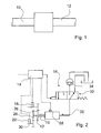
- FIG. 2 shows the torque transmission device FIG. 1 with a control unit 14 and a pressure generating arrangement 16.
- the torque transmission device comprises two speed sensors 18, 20, the signals of which can each be read out via a signal line from the control unit 14.
- the control unit 14 is adapted to evaluate the signals of the two speed sensors 18, 20 for measuring a speed of the first shaft 10 and the speed of the second shaft 12 by an appropriate software that reads out and processes the signals of the speed sensors 18, 20.
- a characteristic curve or a characteristic map is stored in a memory unit, not shown here, of the control unit 14, which at a given pressure in a in FIG. 3 illustrated pressure chamber 22 of an actuating means 24 for adjusting a torque transmission from the first shaft 10 to the second shaft 12 prevailing pressure and depending on the speeds and / or the speed difference indicates the transmitted torque.
- the Drehmomentübernagungshim is part of an internal combustion engine of a truck and the first shaft 10 is connected via a gear 26 to an exhaust turbine, not shown here in an exhaust tract of the engine.
- the second shaft 12 is connected via a further gear 28 with a crankshaft 30 of the internal combustion engine.
- the mediated by the first gear 26 and the second gear 28 translations are chosen such that even at maximum speed of the engine or the crankshaft 30, the speed of the first shaft 10 is higher than the speed of the second shaft 12th
- the control unit 14 is part of an engine control of the internal combustion engine and determines the pressure in the pressure chamber 22 depending on the rotational speeds of the first shaft 10 and the second shaft 12 and depending on the load torque of the internal combustion engine and other engine characteristics such as the amount of air, the injected fuel quantity, different temperatures etc., which are available via a CAN bus.
- the pressure chamber 22 is filled with hydraulic oil, which is fed via an electromagnetic control valve 32 by a pump 34.
- the control unit 14 controls an actuator of the control valve 32 via a control line.
- FIG. 3 shows the torque transmission device from the Figures 1 and 2 in a sectional view.
- the torque transmitting device comprises two rolling bearings 36, 38 for coaxially supporting the first shaft 10 opposite to the second shaft 12 and the adjusting means 24 for adjusting torque transmission from the first shaft 10 to the second shaft 12.
- a first rolling bearing 36 for transmitting torque between the first and the second shaft 12 designed and a second rolling bearing 38 is used for radial mounting of the first shaft 10 on the second shaft 12 is provided.
- the second rolling bearing 38 is formed as a radial cylindrical roller bearing and axially movably attached to the inner ring on the second shaft 12, while the outer ring of the second roller bearing 38 via a collar 40 and a holding member 42 axially and radially fixed in the cavity of the hollow shaft formed second Wave 12 is included.
- the adjusting means 24 is formed as a means for varying an axial load of the first rolling bearing 36.
- the adjusting means 24 comprises, in particular, the pressure chamber 22, the pressure generating arrangement 16 with the pump 34 and the control valve 32, and one arranged in the pressure chamber 22 Spring 44, which is supported on the one hand on a housing 52 of the torque transmitting device and on the other hand rests on an end face 48 of the second shaft 12 via an axial ball bearing 46.
- the front side 48 of the second shaft 12 forms a displaceable wall of the pressure chamber 22 and the second shaft 12 itself is axially displaceably mounted in a bore of the housing 52, the walls of which form the remaining walls of the pressure chamber 22.
- the second shaft 12 acts as an axially displaceable piston or pressure piston 54 in the pressure chamber 22.
- the first shaft 10 is formed as a hollow shaft and receives the second shaft 12 in an interior space.
- the torque transmission device comprises a bearing device 56 composed of two oblique toroidal roller bearings with an opposite bevel for axially and radially fixedly supporting the hollow shaft second shaft 12 in the housing 52.
- the inner ring 58 of the first rolling bearing 36 bears against a step 60 in the profile of the second shaft 12, so that the pressure force acting on the end face 48 of the second shaft 12 in the axial direction is supported via the step 60 on the inner ring 58.
- the adjusting means 24 accordingly comprises a pressure piston 54 acting on the inner ring 58 of the rolling bearing 36.
- the outer ring 62 of the first rolling bearing 36 is supported on a further step 64 in the inner profile of the first shaft 10 designed as a hollow shaft, so that the roller bearings 66 of the first rolling bearing 36 from the inner ring 58 on the outer ring 62 transmitted compressive forces via the further stage 64 are supported on the first shaft 10.
- the rolling bearing 36 is in the in FIG. 3 illustrated embodiment designed as a toroidal bearing oblique raceways, so that a diameter of the slightly curved, conical raceways in the direction of the common axis of rotation of the two shafts 10, 12 tapers.
- the rolling elements 66 slip on the raceways of the inner ring 58 and the outer ring 62.
- the torque transmitting device includes a pressure sensor 68 for measuring the pressure in the pressure chamber 22.
- the control unit 14 detects the pressure in the pressure chamber 22 and compares it with a setpoint. Based on the difference between the detected pressure and the desired value of the pressure in the pressure chamber 22, the control unit 14 regulates the pressure to the desired value.
- the torque transmission device shown is part of an internal combustion engine with an exhaust gas turbine, wherein the exhaust gas turbine via its turbine shaft, the first shaft 10 of the torque transmitting device and wherein the second shaft 12 is connected via the gear 28 with a crankshaft 30 of the internal combustion engine in connection and transmits the torque thereto ( FIG. 2 ).
- the above-described torque transmission device realizes a method of transmitting a drive torque from a first shaft 10 to a second shaft 12 coaxially supported by a rolling bearing 36.
- an axial load of the rolling bearing 36 is varied for adjusting the torque transmission.
- inventive concept is not limited to the embodiment described above.
- the toroidal bearing for example, one or two angular contact ball bearings or tapered roller bearings or tapered bearings could be used.
Landscapes
- Engineering & Computer Science (AREA)
- General Engineering & Computer Science (AREA)
- Mechanical Engineering (AREA)
- Physics & Mathematics (AREA)
- Fluid Mechanics (AREA)
- Chemical & Material Sciences (AREA)
- Combustion & Propulsion (AREA)
- Support Of The Bearing (AREA)
- Friction Gearing (AREA)
- Rolling Contact Bearings (AREA)
- Gear Transmission (AREA)
- General Details Of Gearings (AREA)
Applications Claiming Priority (1)
| Application Number | Priority Date | Filing Date | Title |
|---|---|---|---|
| DE202008016385U DE202008016385U1 (de) | 2008-12-11 | 2008-12-11 | Drehmomentübertragungsvorrichtung |
Publications (3)
| Publication Number | Publication Date |
|---|---|
| EP2196690A2 true EP2196690A2 (fr) | 2010-06-16 |
| EP2196690A3 EP2196690A3 (fr) | 2013-07-03 |
| EP2196690B1 EP2196690B1 (fr) | 2016-03-09 |
Family
ID=41728114
Family Applications (1)
| Application Number | Title | Priority Date | Filing Date |
|---|---|---|---|
| EP09015047.5A Not-in-force EP2196690B1 (fr) | 2008-12-11 | 2009-12-04 | Dispositif de transmission de couple |
Country Status (4)
| Country | Link |
|---|---|
| US (1) | US8793998B2 (fr) |
| EP (1) | EP2196690B1 (fr) |
| CN (1) | CN101818683B (fr) |
| DE (1) | DE202008016385U1 (fr) |
Families Citing this family (2)
| Publication number | Priority date | Publication date | Assignee | Title |
|---|---|---|---|---|
| US9835123B2 (en) | 2015-01-13 | 2017-12-05 | Roller Bearing Company Of America, Inc. | Roller for a fuel pump actuator |
| CN108020358B (zh) * | 2017-12-29 | 2024-02-02 | 深圳市奥酷曼智能技术有限公司 | 周面接触力矩传感器及电动助力车 |
Family Cites Families (24)
| Publication number | Priority date | Publication date | Assignee | Title |
|---|---|---|---|---|
| US1929782A (en) * | 1931-12-09 | 1933-10-10 | New Departure Mfg Co | Clutch |
| GB950728A (en) * | 1959-10-09 | 1964-02-26 | Charles Robson | Mechanical clutch |
| DE2210679A1 (de) * | 1972-03-06 | 1973-09-20 | Walter Schiffer | Lagerkupplung mit begrenzter, vorzugsweise temperaturgesteuerter drehmomentuebertragung |
| DE2403450A1 (de) * | 1974-01-25 | 1975-08-07 | Gerhard Jesse | Reibradgetriebe mit stufenlos veraenderbarem uebersetzungsverhaeltnis |
| FR2413580A1 (fr) * | 1977-12-29 | 1979-07-27 | Vernier Sa G | Systeme d'embrayage |
| JPS5551129A (en) * | 1978-10-05 | 1980-04-14 | Honda Motor Co Ltd | Clutch operation controller for unidirectional clutch |
| DE2948728C2 (de) * | 1979-12-04 | 1982-04-01 | Zahnradfabrik Friedrichshafen Ag, 7990 Friedrichshafen | Elektromagnetisch schaltbare Einflächen-Reibungs-Kupplungs- und -Brems-Kombination |
| JPS61201940A (ja) * | 1985-03-04 | 1986-09-06 | Masao Fukumoto | トルクレリ−サ− |
| GB2241755B (en) * | 1990-03-08 | 1994-01-12 | Kubota Kk | Conical roller type clutch apparatus |
| US5509517A (en) * | 1994-07-15 | 1996-04-23 | Rockwell International Corporation | Flying wedge (centripetal retractor) assembly |
| DE4429855C1 (de) * | 1994-08-23 | 1995-08-17 | Daimler Benz Ag | Aufgeladene Brennkraftmaschine mit mechanischer Hochtriebsmöglichkeit eines Abgasturboladers |
| JPH08277896A (ja) * | 1995-04-06 | 1996-10-22 | Mitsubishi Heavy Ind Ltd | トラクションドライブ装置 |
| DE10008278A1 (de) * | 1999-02-24 | 2000-09-14 | Ntn Toyo Bearing Co Ltd | Vorrichtung zur Leistungsübertragung/-unterbrechung |
| US6464061B1 (en) * | 1999-10-14 | 2002-10-15 | Koyo Seiko Co., Ltd. | Clutch device |
| SE516921C2 (sv) * | 2000-05-31 | 2002-03-19 | Volvo Lastvagnar Ab | Reglerförfarande för tilluftsflödet till en förbränningsmotor samt reglerkrets för utförande av reglerförfarandet |
| DE10058199A1 (de) * | 2000-11-23 | 2002-07-11 | Zahnradfabrik Friedrichshafen | Vorrichtung zum Führen eines Antriebsmoments |
| JP4103539B2 (ja) * | 2002-10-23 | 2008-06-18 | トヨタ自動車株式会社 | 発電機付ターボチャージャを備える内燃機関の制御装置 |
| US7441634B2 (en) * | 2003-12-26 | 2008-10-28 | Nissan Motor Co., Ltd. | Friction drive device |
| EP1718881A1 (fr) * | 2004-02-23 | 2006-11-08 | Timken US Corporation | Embrayage multimode a faible frottement |
| US7490594B2 (en) * | 2004-08-16 | 2009-02-17 | Woodward Governor Company | Super-turbocharger |
| DE102005014347B4 (de) * | 2005-03-24 | 2009-06-18 | Linnig Trucktec Gmbh | Reibschaltkupplung |
| CN101021236A (zh) * | 2006-02-16 | 2007-08-22 | 张恩 | 摩擦滚子式可控滑行节油离合器 |
| DE102006049283B4 (de) * | 2006-10-19 | 2019-03-14 | Zf Friedrichshafen Ag | Vorrichtung zum drehfesten Verbinden einer Welle mit wenigstens einem drehbar auf der Welle gelagerten Losrad |
| JP2008232368A (ja) * | 2007-03-23 | 2008-10-02 | Univance Corp | 駆動力配分装置 |
-
2008
- 2008-12-11 DE DE202008016385U patent/DE202008016385U1/de not_active Expired - Lifetime
-
2009
- 2009-12-04 EP EP09015047.5A patent/EP2196690B1/fr not_active Not-in-force
- 2009-12-10 US US12/653,258 patent/US8793998B2/en not_active Expired - Fee Related
- 2009-12-11 CN CN2009110002943A patent/CN101818683B/zh not_active Expired - Fee Related
Also Published As
| Publication number | Publication date |
|---|---|
| US20100146964A1 (en) | 2010-06-17 |
| CN101818683B (zh) | 2013-09-04 |
| EP2196690A3 (fr) | 2013-07-03 |
| DE202008016385U1 (de) | 2010-04-22 |
| EP2196690B1 (fr) | 2016-03-09 |
| CN101818683A (zh) | 2010-09-01 |
| US8793998B2 (en) | 2014-08-05 |
Similar Documents
| Publication | Publication Date | Title |
|---|---|---|
| EP0377643B1 (fr) | Entrainement mecanique pour surcompresseur de moteur a combustion interne | |
| DE102014112689B4 (de) | Koaxialgetriebe und Anordnung zum Antreiben einer Verstellwelle zum Verstellen des Expansionshubes und/oder des Verdichtungsverhältnisses eines Verbrennungsmotors | |
| DE3130871A1 (de) | Drehmoment-uebertragungssystem | |
| WO2011023282A1 (fr) | Turbine à gaz d'échappement pour un système de turborécupération | |
| EP2283251A1 (fr) | Boîte de vitesses, en particulier boîte de vitesses à double embrayage | |
| EP2381129B1 (fr) | Engrenage, notamment engrenage de compresseur et procédé d'amélioration du comportement de démarrage de celui-ci | |
| DE102005047203A1 (de) | Brennkraftmaschine mit variablem Verdichtungsverhältnis | |
| DE102011015268A1 (de) | Kegelscheibenumschlingungsgetriebe | |
| EP2677162B1 (fr) | Dispositif de démarrage pour le démarrage de moteurs à combustion interne | |
| EP1816368B1 (fr) | Embrayage à ressort hélicoidal | |
| EP2196690B1 (fr) | Dispositif de transmission de couple | |
| DE102014210588A1 (de) | Anordnung zum Antreiben einer Verstellwelle zum Verstellen des Expansionshubes und/oder des Verdichtungsverhältnisses eines Verbrennungsmotors | |
| EP0985855B1 (fr) | Transmission à variation continue du type à poulies coniques et courroie, notamment pour véhicules automoteurs | |
| DE102015204420A1 (de) | Baugruppe für ein Wellgetriebe, Wellgetriebe und Antriebseinheit | |
| EP2318670B1 (fr) | Système de propulsion hybride | |
| DE112006002465B4 (de) | Pumpe | |
| DE102012220719A1 (de) | Kupplungseinrichtung | |
| DE2707791A1 (de) | Fliehkraftreibkupplung | |
| EP1784591B1 (fr) | Transmission a poulies coniques et a courroie, son procede de production, et vehicule equipe de cette transmission | |
| DE112008002352T5 (de) | Lageraufbau | |
| DE102014224946A1 (de) | Umschlingungsgetriebe für ein Kraftfahrzeug | |
| DE10131331A1 (de) | Einrichtung zur Drehmomentübertragung | |
| DE102015208637A1 (de) | Antriebsvorrichtung | |
| EP2491260B1 (fr) | Palier axial avec compensation de décalage et chaîne cinématique le comprenant | |
| DE102010046316B4 (de) | Pumpenantrieb mit Viskokupplung und mechanischer Drehzahlregelung |
Legal Events
| Date | Code | Title | Description |
|---|---|---|---|
| PUAI | Public reference made under article 153(3) epc to a published international application that has entered the european phase |
Free format text: ORIGINAL CODE: 0009012 |
|
| AK | Designated contracting states |
Kind code of ref document: A2 Designated state(s): AT BE BG CH CY CZ DE DK EE ES FI FR GB GR HR HU IE IS IT LI LT LU LV MC MK MT NL NO PL PT RO SE SI SK SM TR |
|
| AX | Request for extension of the european patent |
Extension state: AL BA RS |
|
| PUAL | Search report despatched |
Free format text: ORIGINAL CODE: 0009013 |
|
| AK | Designated contracting states |
Kind code of ref document: A3 Designated state(s): AT BE BG CH CY CZ DE DK EE ES FI FR GB GR HR HU IE IS IT LI LT LU LV MC MK MT NL NO PL PT RO SE SI SK SM TR |
|
| AX | Request for extension of the european patent |
Extension state: AL BA RS |
|
| RIC1 | Information provided on ipc code assigned before grant |
Ipc: F16D 15/00 20060101AFI20130524BHEP |
|
| RBV | Designated contracting states (corrected) |
Designated state(s): AT BE BG CH CY CZ DE DK EE ES FI FR GB GR HR HU IE IS IT LI LT LU LV MC MK MT NL NO PL PT RO SE SI SK SM TR |
|
| 17P | Request for examination filed |
Effective date: 20131219 |
|
| REG | Reference to a national code |
Ref country code: DE Ref legal event code: R079 Ref document number: 502009012206 Country of ref document: DE Free format text: PREVIOUS MAIN CLASS: F16D0015000000 Ipc: F02B0041100000 |
|
| RIC1 | Information provided on ipc code assigned before grant |
Ipc: F02B 41/10 20060101AFI20150421BHEP Ipc: F16D 25/062 20060101ALI20150421BHEP Ipc: F16D 48/06 20060101ALI20150421BHEP Ipc: F16D 15/00 20060101ALI20150421BHEP |
|
| GRAP | Despatch of communication of intention to grant a patent |
Free format text: ORIGINAL CODE: EPIDOSNIGR1 |
|
| INTG | Intention to grant announced |
Effective date: 20150609 |
|
| GRAS | Grant fee paid |
Free format text: ORIGINAL CODE: EPIDOSNIGR3 |
|
| GRAA | (expected) grant |
Free format text: ORIGINAL CODE: 0009210 |
|
| AK | Designated contracting states |
Kind code of ref document: B1 Designated state(s): AT BE BG CH CY CZ DE DK EE ES FI FR GB GR HR HU IE IS IT LI LT LU LV MC MK MT NL NO PL PT RO SE SI SK SM TR |
|
| REG | Reference to a national code |
Ref country code: GB Ref legal event code: FG4D Free format text: NOT ENGLISH |
|
| REG | Reference to a national code |
Ref country code: AT Ref legal event code: REF Ref document number: 779714 Country of ref document: AT Kind code of ref document: T Effective date: 20160315 Ref country code: CH Ref legal event code: EP |
|
| REG | Reference to a national code |
Ref country code: IE Ref legal event code: FG4D Free format text: LANGUAGE OF EP DOCUMENT: GERMAN |
|
| REG | Reference to a national code |
Ref country code: DE Ref legal event code: R096 Ref document number: 502009012206 Country of ref document: DE |
|
| REG | Reference to a national code |
Ref country code: LT Ref legal event code: MG4D |
|
| REG | Reference to a national code |
Ref country code: NL Ref legal event code: MP Effective date: 20160309 |
|
| PG25 | Lapsed in a contracting state [announced via postgrant information from national office to epo] |
Ref country code: HR Free format text: LAPSE BECAUSE OF FAILURE TO SUBMIT A TRANSLATION OF THE DESCRIPTION OR TO PAY THE FEE WITHIN THE PRESCRIBED TIME-LIMIT Effective date: 20160309 Ref country code: GR Free format text: LAPSE BECAUSE OF FAILURE TO SUBMIT A TRANSLATION OF THE DESCRIPTION OR TO PAY THE FEE WITHIN THE PRESCRIBED TIME-LIMIT Effective date: 20160610 Ref country code: NO Free format text: LAPSE BECAUSE OF FAILURE TO SUBMIT A TRANSLATION OF THE DESCRIPTION OR TO PAY THE FEE WITHIN THE PRESCRIBED TIME-LIMIT Effective date: 20160609 Ref country code: ES Free format text: LAPSE BECAUSE OF FAILURE TO SUBMIT A TRANSLATION OF THE DESCRIPTION OR TO PAY THE FEE WITHIN THE PRESCRIBED TIME-LIMIT Effective date: 20160309 Ref country code: FI Free format text: LAPSE BECAUSE OF FAILURE TO SUBMIT A TRANSLATION OF THE DESCRIPTION OR TO PAY THE FEE WITHIN THE PRESCRIBED TIME-LIMIT Effective date: 20160309 |
|
| PG25 | Lapsed in a contracting state [announced via postgrant information from national office to epo] |
Ref country code: LV Free format text: LAPSE BECAUSE OF FAILURE TO SUBMIT A TRANSLATION OF THE DESCRIPTION OR TO PAY THE FEE WITHIN THE PRESCRIBED TIME-LIMIT Effective date: 20160309 Ref country code: SE Free format text: LAPSE BECAUSE OF FAILURE TO SUBMIT A TRANSLATION OF THE DESCRIPTION OR TO PAY THE FEE WITHIN THE PRESCRIBED TIME-LIMIT Effective date: 20160309 Ref country code: PL Free format text: LAPSE BECAUSE OF FAILURE TO SUBMIT A TRANSLATION OF THE DESCRIPTION OR TO PAY THE FEE WITHIN THE PRESCRIBED TIME-LIMIT Effective date: 20160309 Ref country code: LT Free format text: LAPSE BECAUSE OF FAILURE TO SUBMIT A TRANSLATION OF THE DESCRIPTION OR TO PAY THE FEE WITHIN THE PRESCRIBED TIME-LIMIT Effective date: 20160309 Ref country code: NL Free format text: LAPSE BECAUSE OF FAILURE TO SUBMIT A TRANSLATION OF THE DESCRIPTION OR TO PAY THE FEE WITHIN THE PRESCRIBED TIME-LIMIT Effective date: 20160309 |
|
| PG25 | Lapsed in a contracting state [announced via postgrant information from national office to epo] |
Ref country code: EE Free format text: LAPSE BECAUSE OF FAILURE TO SUBMIT A TRANSLATION OF THE DESCRIPTION OR TO PAY THE FEE WITHIN THE PRESCRIBED TIME-LIMIT Effective date: 20160309 Ref country code: IS Free format text: LAPSE BECAUSE OF FAILURE TO SUBMIT A TRANSLATION OF THE DESCRIPTION OR TO PAY THE FEE WITHIN THE PRESCRIBED TIME-LIMIT Effective date: 20160709 |
|
| PG25 | Lapsed in a contracting state [announced via postgrant information from national office to epo] |
Ref country code: PT Free format text: LAPSE BECAUSE OF FAILURE TO SUBMIT A TRANSLATION OF THE DESCRIPTION OR TO PAY THE FEE WITHIN THE PRESCRIBED TIME-LIMIT Effective date: 20160711 Ref country code: CZ Free format text: LAPSE BECAUSE OF FAILURE TO SUBMIT A TRANSLATION OF THE DESCRIPTION OR TO PAY THE FEE WITHIN THE PRESCRIBED TIME-LIMIT Effective date: 20160309 Ref country code: SM Free format text: LAPSE BECAUSE OF FAILURE TO SUBMIT A TRANSLATION OF THE DESCRIPTION OR TO PAY THE FEE WITHIN THE PRESCRIBED TIME-LIMIT Effective date: 20160309 Ref country code: SK Free format text: LAPSE BECAUSE OF FAILURE TO SUBMIT A TRANSLATION OF THE DESCRIPTION OR TO PAY THE FEE WITHIN THE PRESCRIBED TIME-LIMIT Effective date: 20160309 Ref country code: RO Free format text: LAPSE BECAUSE OF FAILURE TO SUBMIT A TRANSLATION OF THE DESCRIPTION OR TO PAY THE FEE WITHIN THE PRESCRIBED TIME-LIMIT Effective date: 20160309 |
|
| REG | Reference to a national code |
Ref country code: DE Ref legal event code: R097 Ref document number: 502009012206 Country of ref document: DE |
|
| PG25 | Lapsed in a contracting state [announced via postgrant information from national office to epo] |
Ref country code: IT Free format text: LAPSE BECAUSE OF FAILURE TO SUBMIT A TRANSLATION OF THE DESCRIPTION OR TO PAY THE FEE WITHIN THE PRESCRIBED TIME-LIMIT Effective date: 20160309 |
|
| PLBE | No opposition filed within time limit |
Free format text: ORIGINAL CODE: 0009261 |
|
| STAA | Information on the status of an ep patent application or granted ep patent |
Free format text: STATUS: NO OPPOSITION FILED WITHIN TIME LIMIT |
|
| PG25 | Lapsed in a contracting state [announced via postgrant information from national office to epo] |
Ref country code: DK Free format text: LAPSE BECAUSE OF FAILURE TO SUBMIT A TRANSLATION OF THE DESCRIPTION OR TO PAY THE FEE WITHIN THE PRESCRIBED TIME-LIMIT Effective date: 20160309 |
|
| 26N | No opposition filed |
Effective date: 20161212 |
|
| PG25 | Lapsed in a contracting state [announced via postgrant information from national office to epo] |
Ref country code: BG Free format text: LAPSE BECAUSE OF FAILURE TO SUBMIT A TRANSLATION OF THE DESCRIPTION OR TO PAY THE FEE WITHIN THE PRESCRIBED TIME-LIMIT Effective date: 20160609 |
|
| PG25 | Lapsed in a contracting state [announced via postgrant information from national office to epo] |
Ref country code: BE Free format text: LAPSE BECAUSE OF NON-PAYMENT OF DUE FEES Effective date: 20161231 Ref country code: SI Free format text: LAPSE BECAUSE OF FAILURE TO SUBMIT A TRANSLATION OF THE DESCRIPTION OR TO PAY THE FEE WITHIN THE PRESCRIBED TIME-LIMIT Effective date: 20160309 |
|
| REG | Reference to a national code |
Ref country code: DE Ref legal event code: R119 Ref document number: 502009012206 Country of ref document: DE |
|
| REG | Reference to a national code |
Ref country code: CH Ref legal event code: PL |
|
| GBPC | Gb: european patent ceased through non-payment of renewal fee |
Effective date: 20161204 |
|
| PG25 | Lapsed in a contracting state [announced via postgrant information from national office to epo] |
Ref country code: MC Free format text: LAPSE BECAUSE OF FAILURE TO SUBMIT A TRANSLATION OF THE DESCRIPTION OR TO PAY THE FEE WITHIN THE PRESCRIBED TIME-LIMIT Effective date: 20160309 |
|
| REG | Reference to a national code |
Ref country code: FR Ref legal event code: ST Effective date: 20170831 |
|
| REG | Reference to a national code |
Ref country code: IE Ref legal event code: MM4A |
|
| PG25 | Lapsed in a contracting state [announced via postgrant information from national office to epo] |
Ref country code: FR Free format text: LAPSE BECAUSE OF NON-PAYMENT OF DUE FEES Effective date: 20170102 Ref country code: LI Free format text: LAPSE BECAUSE OF NON-PAYMENT OF DUE FEES Effective date: 20161231 Ref country code: CH Free format text: LAPSE BECAUSE OF NON-PAYMENT OF DUE FEES Effective date: 20161231 Ref country code: LU Free format text: LAPSE BECAUSE OF NON-PAYMENT OF DUE FEES Effective date: 20161204 |
|
| PG25 | Lapsed in a contracting state [announced via postgrant information from national office to epo] |
Ref country code: GB Free format text: LAPSE BECAUSE OF NON-PAYMENT OF DUE FEES Effective date: 20161204 Ref country code: DE Free format text: LAPSE BECAUSE OF NON-PAYMENT OF DUE FEES Effective date: 20170701 Ref country code: IE Free format text: LAPSE BECAUSE OF NON-PAYMENT OF DUE FEES Effective date: 20161204 |
|
| REG | Reference to a national code |
Ref country code: BE Ref legal event code: MM Effective date: 20161231 |
|
| REG | Reference to a national code |
Ref country code: AT Ref legal event code: MM01 Ref document number: 779714 Country of ref document: AT Kind code of ref document: T Effective date: 20161204 |
|
| PG25 | Lapsed in a contracting state [announced via postgrant information from national office to epo] |
Ref country code: CY Free format text: LAPSE BECAUSE OF FAILURE TO SUBMIT A TRANSLATION OF THE DESCRIPTION OR TO PAY THE FEE WITHIN THE PRESCRIBED TIME-LIMIT Effective date: 20160309 Ref country code: AT Free format text: LAPSE BECAUSE OF NON-PAYMENT OF DUE FEES Effective date: 20161204 Ref country code: HU Free format text: LAPSE BECAUSE OF FAILURE TO SUBMIT A TRANSLATION OF THE DESCRIPTION OR TO PAY THE FEE WITHIN THE PRESCRIBED TIME-LIMIT; INVALID AB INITIO Effective date: 20091204 |
|
| PG25 | Lapsed in a contracting state [announced via postgrant information from national office to epo] |
Ref country code: MK Free format text: LAPSE BECAUSE OF FAILURE TO SUBMIT A TRANSLATION OF THE DESCRIPTION OR TO PAY THE FEE WITHIN THE PRESCRIBED TIME-LIMIT Effective date: 20160309 Ref country code: TR Free format text: LAPSE BECAUSE OF FAILURE TO SUBMIT A TRANSLATION OF THE DESCRIPTION OR TO PAY THE FEE WITHIN THE PRESCRIBED TIME-LIMIT Effective date: 20160309 |
|
| PG25 | Lapsed in a contracting state [announced via postgrant information from national office to epo] |
Ref country code: MT Free format text: LAPSE BECAUSE OF FAILURE TO SUBMIT A TRANSLATION OF THE DESCRIPTION OR TO PAY THE FEE WITHIN THE PRESCRIBED TIME-LIMIT Effective date: 20160309 |