EP2196743A2 - Thermodynamische Vorrichtung mit Multi-Source-Multienergie-Heisswassertank - Google Patents
Thermodynamische Vorrichtung mit Multi-Source-Multienergie-Heisswassertank Download PDFInfo
- Publication number
- EP2196743A2 EP2196743A2 EP09015361A EP09015361A EP2196743A2 EP 2196743 A2 EP2196743 A2 EP 2196743A2 EP 09015361 A EP09015361 A EP 09015361A EP 09015361 A EP09015361 A EP 09015361A EP 2196743 A2 EP2196743 A2 EP 2196743A2
- Authority
- EP
- European Patent Office
- Prior art keywords
- heat pump
- heat
- heating
- water
- balloon
- Prior art date
- Legal status (The legal status is an assumption and is not a legal conclusion. Google has not performed a legal analysis and makes no representation as to the accuracy of the status listed.)
- Withdrawn
Links
Images


Classifications
-
- F—MECHANICAL ENGINEERING; LIGHTING; HEATING; WEAPONS; BLASTING
- F24—HEATING; RANGES; VENTILATING
- F24H—FLUID HEATERS, e.g. WATER OR AIR HEATERS, HAVING HEAT-GENERATING MEANS, e.g. HEAT PUMPS, IN GENERAL
- F24H4/00—Fluid heaters characterised by the use of heat pumps
- F24H4/02—Water heaters
- F24H4/04—Storage heaters
-
- F—MECHANICAL ENGINEERING; LIGHTING; HEATING; WEAPONS; BLASTING
- F24—HEATING; RANGES; VENTILATING
- F24D—DOMESTIC- OR SPACE-HEATING SYSTEMS, e.g. CENTRAL HEATING SYSTEMS; DOMESTIC HOT-WATER SUPPLY SYSTEMS; ELEMENTS OR COMPONENTS THEREFOR
- F24D2200/00—Heat sources or energy sources
- F24D2200/08—Electric heater
Definitions
- the invention relates to heating and storage devices for domestic hot water and water or other heat transfer fluid for heating or cooling a building or swimming pool.
- the device according to the invention comprises a thermodynamic device of the heat pump type, and a balloon for storing hot water, type domestic hot water on the one hand, and a heat transfer fluid, at a temperature generally lower than that of domestic hot water, intended in particular for the heating or cooling of buildings on the other hand.
- thermodynamic devices for the combined heating of domestic hot water and a fluid for heating a building. These devices can also allow the cooling of the fluid in the case of a reversible thermodynamic device.
- Balloons for storing hot water at different temperatures are also known.
- the balloon described in the application FR 2,905,750 (JB Hurier ) comprises a first tank defined by a first wall and intended to contain water for sanitary purposes, and a second tank delimited by a second wall and intended to contain a heat-transfer fluid for heating purposes, such as water.
- This balloon is characterized in that the first tank is arranged at least partly inside the second tank so as to transfer heat from the sanitary water to the heat transfer fluid and thus heat the latter to wear it. at a second temperature, substantially less than or equal to the first temperature.
- This balloon does not allow the simultaneous storage of hot and cold water, in particular because the parts hot water / "warm” water (generally intended for space heating) are not thermally insulated any of the other, and that the storage of cold water would lead to a cooling of the hot water.
- the document US 4,350,200 relates to a solar energy collector.
- the invention relates to a system operable with a solar collector, comprising a cold liquid reservoir in which the heat is stored at a relatively low temperature and a hot liquid reservoir in which the heat is stored at a high temperature, and a heat pump for transferring heat from the cold liquid reservoir to the hot liquid reservoir, and heat exchangers in each of the reservoirs.
- the document US 4,524,909 discloses an apparatus for producing domestic hot water and heating, which may comprise a heat pump and a boiler.
- the apparatus includes a storage tank for the heating water of the radiators and a hot water storage tank.
- the document DE 198 15 521 relates to a heat recovery system for heating buildings. Heating sources are solar panels or boilers. Storage is done through latent heat storage elements. The system described in this document does not include a heat pump.
- the document US 4,037,650 relates to a heat storage apparatus comprising two storage containers, each container containing a thermal storage medium, one of the media being able to be maintained at a temperature below a predetermined temperature and the second medium being able to be maintained at a temperature above a predefined temperature, a thermodynamic refrigeration system transfers the heat from the medium at low temperature to the medium at high temperature.
- the demand WO 2006/101404 discloses a device comprising a water storage tank, a heat pump for transferring heat and / or cold to the water of the tank, the balloon comprising at least two separate tanks for the thermal storage of hot and / or cold water and / or ice, the tanks being thermally insulated from each other.
- the first tank exchanges heat with the heat pump through a first heat exchanger at a first temperature level
- the second tank exchanges heat with the heat pump through a second heat exchanger at a second level. temperature higher than the first temperature level.
- the disadvantage of this device is that it has limited domestic hot water production capacity, because domestic hot water is produced using the desuperheating of the compressor. In practice, this device can not produce water only when it produces hot or cold water for heating or cooling at the same time.
- the document EP 0 240 441 It concerns a three-function heat pump system, namely the heating of a space, the cooling of a space and the heating of sanitary water.
- the heat pump is reversible, the system has two storage tanks of water or heat transfer liquid at two different temperatures, which allow the compressor to operate at the most favorable times, for example when electricity is provided at a reduced rate.
- the first balloon is of relatively large size, and intended for heating / cooling a space.
- the second balloon is smaller than the first and is intended for heating the sanitary water. If necessary, domestic hot water and / or heat transfer liquid can be taken in the respective balloons without mandatory immediate operation of the compressor.
- the heat pump described in the document EP 0 240 441 necessarily includes two condensers (in heating mode), one placed in the flask for heating / cooling a space, the second placed in the hot water tank; moreover a refrigerant coil is placed in the hot water tank, which is prohibited by the regulations in force in France and more generally in Europe.
- the problem that the present invention proposes to solve is to provide a device, comprising a one-piece balloon provided with two tanks, and for heating water (such as domestic hot water) and, separately and independently, the heating or cooling water or another heat transfer fluid, for heating and cooling, and said balloon also allowing the simultaneous storage of hot water (such as domestic hot water) and a lukewarm heat transfer fluid or cold (such as water for space heating or cooling).
- a device comprising a one-piece balloon provided with two tanks, and for heating water (such as domestic hot water) and, separately and independently, the heating or cooling water or another heat transfer fluid, for heating and cooling, and said balloon also allowing the simultaneous storage of hot water (such as domestic hot water) and a lukewarm heat transfer fluid or cold (such as water for space heating or cooling).
- the problem that the present invention proposes to solve is to provide a device, comprising a one-piece balloon provided with two tanks, and allowing the heating of water (such as domestic hot water) and, separately and independently, the heating or cooling of water or other coolant, for heating and cooling, and said balloon also allowing simultaneous storage of hot water (such as domestic hot water) and a lukewarm or cold heat transfer liquid (such as water for space heating or cooling), with a smaller footprint compared to that of existing devices in the state of the art.
- water such as domestic hot water
- a lukewarm or cold heat transfer liquid such as water for space heating or cooling
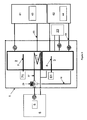
- a combined device for producing water at two different temperatures T1 and T2 comprising a heat pump 5 and a balloon 1 divided into two parts 2, 3, in which the two parts 2 , 3 said balloon 1 form, for part 2 a hot water tank, and for part 3 a balloon called "disconnection balloon".
- the two parts 2, 3 of the balloon 1 are thermally and hydraulically isolated from each other.
- the domestic hot water tank 2 contains a heat exchanger 8.
- the heat exchanger 8 of the domestic hot water tank 2 and the uncoupling tank 3 can both exchange heat with the condenser (in heating mode ) or the evaporator (in cooling mode) of the heat pump 5, through a three-way valve 29.
- Such a device is shown schematically on the figure 1 . It comprises a so-called mixed balloon 1 allowing the simultaneous management of water at a temperature T1 and a coolant such as water at a temperature T2 different from T1, the water and the heat transfer fluid being respectively brought to the temperatures T1 and T2 by a heat pump 5.
- the mixed balloon of the present invention allows the heating and / or cooling of the heat transfer fluid of a hydraulic heating / air conditioning circuit and the heating of domestic hot water.
- the water or other cold heat transfer fluid has, according to the intended use, a temperature T2 of between about 6 ° C and 12 ° C for direct use in air conditioning, and between about 15 and 18 ° C for use in a heated floor operating in cooling mode.
- the coolant of the uncoupling tank 3 has, according to the intended use, a temperature T2 of between 27 and 45 ° C, preferably 35 ° C for use in underfloor heating or with ventiloconvectors or low temperature radiators, and a T2 temperature between 45 ° C and 65 ° C for use with conventional radiators. Most often and preferably, T2 is less than T1.
- the domestic hot water tank 2 and the uncoupling tank 3 are further thermally insulated from each other. This thermal insulation allows the simultaneous storage of domestic hot water at a temperature T1 between 50 ° C and 70 ° C in the tank 2 and a cold heat transfer fluid at a temperature T2 between 6 ° C and 18 ° C intended the air conditioning in the uncoupling tank 3 without heat exchange between the domestic hot water tank 2 and the uncoupling tank 3.
- the domestic hot water tank 2 and the uncoupling tank 3 are not in hydraulic contact with each other, one being intended to contain water for domestic use, and the other a heat transfer fluid which may be water, but also brine, or other antifreeze heat transfer fluid for example, and intended in particular for heating and / or cooling buildings.
- a heat transfer fluid which may be water, but also brine, or other antifreeze heat transfer fluid for example, and intended in particular for heating and / or cooling buildings.
- a heat exchanger 8 for example a coil, connected to the heat pump 5 by a hydraulic circuit 37 and placed in the domestic hot water tank 2, allows heat exchange with the heat pump 5 in order to heat the heat.
- sanitary hot water by circulation of a coolant which takes heat from the condenser (not shown) of the heat pump.
- the uncoupling tank 3 is connected to the heat pump 5 by a hydraulic circuit 18 in which circulates a coolant.
- the uncoupling tank 3 is furthermore connected to the heating and / or air conditioning devices 13, 22, 36 by hydraulic circuits 21, 33, 38, in which the coolant circulates as well.
- the coolant such as water or brine
- the uncoupling tank 3 acts as a buffer to prevent short cycles of the compressor of the heat pump.
- This type of balloon, or bottle is commonly used in hydraulic heating / cooling circuits in cases where the volume of liquid in the circuits is low.
- the uncoupling drum 3 also has the function of mixing the heat transfer fluid of the hydraulic circuits 21, 33, 38 of the heating / cooling apparatus of the buildings 22, 36, 13 with the heat transfer fluid heated or cooled by the heat pump 5.
- the heat pump 5 of the device according to the invention can be of any known type for heating and / or cooling buildings with a heat transfer liquid. It may be for example a monobloc or split heat pump, air / water or geothermal / water.
- the heat sources may be outside air and / or extract air from ventilation and / or a mixture of outside air and extract air from ventilation. .
- the geothermal / water type heat pumps may be ground / water type heat pumps, ie heat pumps using as a source or sensor a loop of refrigerant passing into the external ground.
- the geothermal / water type heat pumps can also be of the brine / water type, that is to say heat pumps using as a source or sensor a brine loop passing into the external ground.
- the geothermal / water type heat pumps can also be water / water type, that is to say heat pumps using as source or sensor an "open" loop on the water of a water table or a river.
- the heat pump 5 of the device according to the invention is a low-temperature heat pump, and at least one of the associated heating / air-conditioning units 22, 36 is a floor heating, possibly refreshing, or a fan-coil , or low temperature radiator.
- the low-temperature heat pump 5 heats the heat transfer fluid of the uncoupling tank 3 at a temperature T2 advantageously between 27 ° C and 45 ° C, preferably 35 ° C.
- the heat pump 5 of the device according to the invention is a high temperature heat pump and the associated heating / air-conditioning units 22, 36 are radiators or convectors.
- the high temperature heat pump heats the heat transfer fluid of the uncoupling tank 3 at a temperature T2 advantageously between 50 ° C and 65 ° C.
- the device according to the invention is provided with at least two heating / air conditioning units 22, 36 placed in two different zones of a building, and operating with possibly different heat transfer fluid temperatures. .
- the temperature of each zone is regulated by the temperature control devices 19, 20. These devices control the actuation of the circulators (or pumps) 25, 26.
- the heat energy required for heating the domestic hot water is supplied by the condenser (not shown in the drawings) of the heat pump 5.
- the heating of the domestic hot water is achieved by heat exchange with heat transfer liquid through the heat exchanger 8, and not by heat exchange with refrigerant as in other devices of the state of the technical. Indeed, the regulations in force in Europe prohibit the use of a heat exchanger containing refrigerant in the water balloons intended for domestic or sanitary use.
- the mixed balloon 1 makes it possible to simultaneously store water and heat transfer fluid at two different temperatures T1 and T2, respectively.
- thermal insulation between the domestic hot water tank 2 and the uncoupling tank 3 obtained for example by placing between the two flasks a sufficient quantity of an effective thermal insulator such as polyurethane foam, glass wool, rock wool, expanded polystyrene.
- An environmentally friendly or natural non-polluting insulator, such as sheep's wool or hemp wool may advantageously be used.
- An electrical resistor 6 can be placed on the coolant circuit, either in the heat pump 5, as shown in FIG. figure 1 , either in the uncoupling drum 3, as shown in FIG. figure 3 at another point in the hydraulic circuit, as shown on the figure 2 .
- This is a booster resistance to overcome the lack of power of the heat pump 5, for example in the case of an air / water heat pump when the outside temperature is very low.
- a three-way valve 29 placed in the heat transfer fluid circuit at the outlet of the heat pump 5 makes it possible to send said coolant either to the heat exchanger 8 of the domestic hot water tank 2 or to the uncoupling tank 3 as required.
- the heat pump 5 is a reversible heat pump, capable, as needed, of heating or cooling a heat transfer fluid such as water, thanks to an inversion of its thermodynamic cycle (the condenser becomes the evaporator and vice versa).
- a control module reverses the operation of the heat pump 5, which then heats the coolant, which is sent in the exchanger 8 of the domestic hot water tank 2, thanks to the three-way valve 29.
- the device according to the invention further comprises a solar thermal panel 9.
- a heat exchanger 10 for example a coil, connected to the solar thermal panel 9 by a hydraulic circuit, and placed in the balloon domestic hot water 2, to heat the water of the domestic hot water tank 2.
- Another heat exchanger 11 connected to the solar thermal panel by a hydraulic circuit and placed in the uncoupling tank 3 allows to heat the water of uncoupling balloon 3.
- a three-way valve 32 placed in the heat transfer fluid circuit of the solar thermal panel 9 makes it possible to send the coolant either to the heat exchanger 10 of the domestic hot water tank 2 or to the heat exchanger 11 of the balloon uncoupling 3 as required.
- a boiler 12 is used as an additional means of heating the water of the uncoupling tank 3.
- the boiler 12 can be a wood boiler, gas, fuel oil, electric resistances, or a chimney equipped with a system for extracting hot air.
- the boiler 12 may be of interest when the power of the heat pump is limited, for example in the case of an air / water heat pump when the outside temperatures are very low.
- the uncoupling flask 3 further comprises a heat exchanger 15 for heating or cooling the water of a swimming pool 14.
- a heat exchanger 15 for heating or cooling the water of a swimming pool 14.
- This embodiment also makes it possible to dispose of any overproduction of water. hot by the solar thermal panel 9, heating a pool 14 acting in this case as a heat sink of almost infinite capacity.
- the use of the solar thermal panel for the heating of the water of a swimming pool also allows to have a free and renewable thermal energy.
- the device according to the invention is provided with a housing or electronic control module (not shown).
- This housing makes it possible to control the various components of the device such as the three-way valves 29, 30, 31, 32, the starting or stopping of the compressor (not shown) of the heat pump 5 as a function of the heating requirements of domestic hot water and / or heating and cooling of the heat transfer fluid contained in the uncoupling tank 3.
- the control box is programmed to take into account in particular, but without limitation, the outside temperature measured by the external sensor 17 and the water law of the heat pump 5.
- the term "water law” means a control function which makes it possible to control the temperature of the heating water as a function of the outside temperature.
- the device according to the invention further comprises storage blocks of the heat energy 41, 42, 43, 44.
- These energy storage blocks may consist for example of composite materials. graphite / paraffin, or comprise such composite materials; these composite materials are part of the state of the art. In this case, it is a storage mainly by latent heat.
- the heat energy storage blocks 41, 42, 43, 44 may be placed in the domestic hot water tank 2 and / or in the uncoupling tank 3 and / or in one or more containers located outside. at least one of these balls 2, 3 and can be used to store heat, for example during overproduction, or when the user benefits from a lower rate at certain times ("off-peak hours") for electricity, and then return this heat for heating the domestic hot water of the tank 2 and / or the heating or cooling of the heat transfer fluid of the uncoupling tank 3.
- the storage blocks of the heat energy 43, 44 are placed in additional balloons 61, 62, as represented by FIG. figure 3 .
- the additional balloons 61, 62 are respectively connected to the domestic hot water tank 2 and to the uncoupling tank 3 by means of hydraulic circuits 63, 64.
- the heat is stored in blocks 43 and / or 44 to be used thereafter as needed.
- the device according to the invention comprises a single additional tank 61 connected to the domestic hot water tank 2 or a single additional tank 62 connected to the uncoupling tank 3.
- a first advantage of the device according to the invention is its simplicity: in heating mode it has only one condenser.
- Another advantage of the device according to the invention compared to those of the state of the art is that it has both a high hot water production capacity, and great flexibility of operation.
- the heat energy required for heating the domestic hot water is provided by the condenser (not shown) of the heat pump 5.
- the mixed balloon 1 consisting of two parts 2, 3 thermally insulated from each other, can simultaneously store water and heat transfer fluid at two different temperatures.
- the device according to the invention thus has a great flexibility of operation. Indeed, the device according to the invention can, simultaneously, use the domestic hot water of the balloon 2 according to the needs of users, and heat or cool a space of a building using the coolant contained in the uncoupling balloon 3. At the same time, the heat pump 5 is used either to heat the domestic hot water, or to heat or cool the heat transfer fluid of the uncoupling tank 3.
- the device according to the invention can be installed for example in replacement of a gas or oil boiler with storage tank of domestic hot water, which allows the realization of energy savings, this without substantially increasing the total internal space used by the heating and hot water system.
- the mixed balloon 1 used in the device according to the invention can easily, with some adjustments that do not depart from the scope of the present invention, be connected to a conventional heat pump, such as a monobloc pump air / water or air / air, or a split heat pump with a hydraulic module connected to the unit interior. Therefore, the device according to the invention can be obtained by replacing the existing domestic hot water production device (and in particular an electric cumulus) of a housing also equipped with a heat pump, by the mixed balloon. 1 of the device according to the invention, also allowing a substantial saving of energy.
- a conventional heat pump such as a monobloc pump air / water or air / air, or a split heat pump with a hydraulic module connected to the unit interior. Therefore, the device according to the invention can be obtained by replacing the existing domestic hot water production device (and in particular an electric cumulus) of a housing also equipped with a heat pump, by the mixed balloon. 1 of the device according to the invention, also allowing a substantial saving of energy.
Landscapes
- Engineering & Computer Science (AREA)
- Physics & Mathematics (AREA)
- Thermal Sciences (AREA)
- Chemical & Material Sciences (AREA)
- Combustion & Propulsion (AREA)
- Mechanical Engineering (AREA)
- General Engineering & Computer Science (AREA)
- Heat-Pump Type And Storage Water Heaters (AREA)
- Steam Or Hot-Water Central Heating Systems (AREA)
- Central Heating Systems (AREA)
Applications Claiming Priority (1)
| Application Number | Priority Date | Filing Date | Title |
|---|---|---|---|
| FR0806981A FR2939874B1 (fr) | 2008-12-12 | 2008-12-12 | Dispositif thermodynamique avec ballon d'eau chaude multi-energies mulit-sources |
Publications (2)
| Publication Number | Publication Date |
|---|---|
| EP2196743A2 true EP2196743A2 (de) | 2010-06-16 |
| EP2196743A3 EP2196743A3 (de) | 2016-05-18 |
Family
ID=40912052
Family Applications (1)
| Application Number | Title | Priority Date | Filing Date |
|---|---|---|---|
| EP09015361.0A Withdrawn EP2196743A3 (de) | 2008-12-12 | 2009-12-11 | Thermodynamische Vorrichtung mit Multi-Source-Multienergie-Heisswassertank |
Country Status (2)
| Country | Link |
|---|---|
| EP (1) | EP2196743A3 (de) |
| FR (1) | FR2939874B1 (de) |
Cited By (7)
| Publication number | Priority date | Publication date | Assignee | Title |
|---|---|---|---|---|
| CN107062465A (zh) * | 2017-01-16 | 2017-08-18 | 吴焕雄 | 一种具有生产洁净水、空调功能的组合系统 |
| ITUA20164324A1 (it) * | 2016-06-13 | 2017-12-13 | Adsum S R L | Centrale plug&play per generare acqua calda sanitaria e relativo metodo di controllo |
| CN110030612A (zh) * | 2019-04-18 | 2019-07-19 | 太原向明智能装备股份有限公司 | 一种多能互补矿井供热管网系统 |
| CN110186103A (zh) * | 2019-07-03 | 2019-08-30 | 天津理工大学 | 一种复合能源供热系统和方法 |
| CN114877508A (zh) * | 2022-06-01 | 2022-08-09 | 国家电投集团东北电力有限公司大连大发能源分公司 | 一种可再生能源驱动的室温调节系统 |
| IT202200012803A1 (it) * | 2022-06-16 | 2023-12-16 | Cordivari S R L | Sistema compatto di accumulo e scambio termico per impianti solari termici, relativo impianto e metodo |
| EP4498002A1 (de) * | 2023-07-28 | 2025-01-29 | Vaillant GmbH | Pufferspeicher, heizungsanlage und verfahren zu deren betrieb |
Citations (7)
| Publication number | Priority date | Publication date | Assignee | Title |
|---|---|---|---|---|
| US4037650A (en) | 1975-05-23 | 1977-07-26 | National Research Development Corporation | Thermal storage apparatus |
| US4350200A (en) | 1978-07-24 | 1982-09-21 | Mcelwain John A | Solar energy collector and system |
| US4524909A (en) | 1982-11-15 | 1985-06-25 | Ingemar Persson | Apparatus for production of hot tap water |
| EP0240441A2 (de) | 1986-03-27 | 1987-10-07 | Phenix Heat Pump Systems, Inc. | Dreiwegwärmepumpenvorrichtung und Verfahren |
| DE19815521A1 (de) | 1998-04-07 | 1999-10-14 | Dieter Weinhold | Verfahren und Vorrichtung zur Versorgung von Gebäuden mit Wärme aus einem Wärmespeicher mit eingebauten Wärmetauschern |
| WO2006101404A2 (en) | 2005-03-23 | 2006-09-28 | Kjell Emil Eriksen | A system for utilization of thermal energy |
| FR2905750A1 (fr) | 2006-09-13 | 2008-03-14 | Jean Bernard Hurier | Combine chaudiere / chauffe-eau sanitaire. |
Family Cites Families (11)
| Publication number | Priority date | Publication date | Assignee | Title |
|---|---|---|---|---|
| US3207358A (en) * | 1961-07-27 | 1965-09-21 | Gen Electric | Water storage tanks and methods of making the same |
| US4380156A (en) * | 1979-06-04 | 1983-04-19 | Atlantic Richfield Company | Multiple source heat pump |
| DK348279A (da) * | 1979-08-21 | 1981-02-22 | Genvex Energiteknik | Varmeveksler |
| US4308042A (en) * | 1980-04-11 | 1981-12-29 | Atlantic Richfield Company | Heat pump with freeze-up prevention |
| DE3044684A1 (de) * | 1980-11-27 | 1982-07-08 | Günter 2370 Rendsburg Braun | Einrichtung zur energiegewinnung mittels einer absorberflaeche und einer waermepumpe |
| DE3227925A1 (de) * | 1981-07-29 | 1983-02-17 | Alfa-Laval Stalltechnik GmbH, 1120 Wien | Heizungsanlage |
| DE3535752A1 (de) * | 1985-10-07 | 1987-04-09 | Siebel Achenbach & Braun Behae | Druckbehaelter |
| CN1247944C (zh) * | 2003-12-17 | 2006-03-29 | 华南理工大学 | 储热式热泵空调装置的储热器及其储热材料的制备方法 |
| NO326274B1 (no) * | 2005-03-23 | 2008-10-27 | Kjell Emil Eriksen | System og fremgangsmate for utnyttelse av energi |
| US7923112B2 (en) * | 2005-05-12 | 2011-04-12 | Sgl Carbon Se | Latent heat storage material and process for manufacture of the latent heat storage material |
| FR2899671B1 (fr) * | 2006-04-11 | 2015-03-06 | Michel Louis Dupraz | Systeme de chauffage, rafraichissement et production d'eau chaude sanitaire par capteur solaire combine avec une thermopompe et une reserve thermique a basse temperature. |
-
2008
- 2008-12-12 FR FR0806981A patent/FR2939874B1/fr not_active Expired - Fee Related
-
2009
- 2009-12-11 EP EP09015361.0A patent/EP2196743A3/de not_active Withdrawn
Patent Citations (7)
| Publication number | Priority date | Publication date | Assignee | Title |
|---|---|---|---|---|
| US4037650A (en) | 1975-05-23 | 1977-07-26 | National Research Development Corporation | Thermal storage apparatus |
| US4350200A (en) | 1978-07-24 | 1982-09-21 | Mcelwain John A | Solar energy collector and system |
| US4524909A (en) | 1982-11-15 | 1985-06-25 | Ingemar Persson | Apparatus for production of hot tap water |
| EP0240441A2 (de) | 1986-03-27 | 1987-10-07 | Phenix Heat Pump Systems, Inc. | Dreiwegwärmepumpenvorrichtung und Verfahren |
| DE19815521A1 (de) | 1998-04-07 | 1999-10-14 | Dieter Weinhold | Verfahren und Vorrichtung zur Versorgung von Gebäuden mit Wärme aus einem Wärmespeicher mit eingebauten Wärmetauschern |
| WO2006101404A2 (en) | 2005-03-23 | 2006-09-28 | Kjell Emil Eriksen | A system for utilization of thermal energy |
| FR2905750A1 (fr) | 2006-09-13 | 2008-03-14 | Jean Bernard Hurier | Combine chaudiere / chauffe-eau sanitaire. |
Cited By (10)
| Publication number | Priority date | Publication date | Assignee | Title |
|---|---|---|---|---|
| ITUA20164324A1 (it) * | 2016-06-13 | 2017-12-13 | Adsum S R L | Centrale plug&play per generare acqua calda sanitaria e relativo metodo di controllo |
| CN107062465A (zh) * | 2017-01-16 | 2017-08-18 | 吴焕雄 | 一种具有生产洁净水、空调功能的组合系统 |
| CN110030612A (zh) * | 2019-04-18 | 2019-07-19 | 太原向明智能装备股份有限公司 | 一种多能互补矿井供热管网系统 |
| CN110186103A (zh) * | 2019-07-03 | 2019-08-30 | 天津理工大学 | 一种复合能源供热系统和方法 |
| CN110186103B (zh) * | 2019-07-03 | 2024-01-30 | 天津理工大学 | 一种复合能源供热系统和方法 |
| CN114877508A (zh) * | 2022-06-01 | 2022-08-09 | 国家电投集团东北电力有限公司大连大发能源分公司 | 一种可再生能源驱动的室温调节系统 |
| CN114877508B (zh) * | 2022-06-01 | 2023-09-01 | 国家电投集团东北电力有限公司大连大发能源分公司 | 一种可再生能源驱动的室温调节系统 |
| IT202200012803A1 (it) * | 2022-06-16 | 2023-12-16 | Cordivari S R L | Sistema compatto di accumulo e scambio termico per impianti solari termici, relativo impianto e metodo |
| EP4293307A1 (de) * | 2022-06-16 | 2023-12-20 | Cordivari S.r.l. | Kompaktes lager- und wärmeaustauschsystem für thermische systeme, entsprechende anlage und verfahren |
| EP4498002A1 (de) * | 2023-07-28 | 2025-01-29 | Vaillant GmbH | Pufferspeicher, heizungsanlage und verfahren zu deren betrieb |
Also Published As
| Publication number | Publication date |
|---|---|
| FR2939874A1 (fr) | 2010-06-18 |
| EP2196743A3 (de) | 2016-05-18 |
| FR2939874B1 (fr) | 2010-12-31 |
Similar Documents
| Publication | Publication Date | Title |
|---|---|---|
| US7827814B2 (en) | Geothermal water heater | |
| EP2196743A2 (de) | Thermodynamische Vorrichtung mit Multi-Source-Multienergie-Heisswassertank | |
| CN102077050B (zh) | 能量储存系统 | |
| US9657998B2 (en) | Method for operating an arrangement for storing thermal energy | |
| CN102483311B (zh) | 储热系统 | |
| US20110083827A1 (en) | Cooling system with integral thermal energy storage | |
| WO2011015731A1 (fr) | Dispositif thermodynamique multi-énergie modulaire | |
| EP1978311A2 (de) | Von einer anderen Energiequelle unabhängiges und unabhängiges Sonnenheizungssystem | |
| EP2592358A1 (de) | Anlage zur Temperaturregelung und Warmwassererzeugung, und Methode zur Umsetzung einer solchen Anlage | |
| US10883728B2 (en) | Broad band district heating and cooling system | |
| CN105431686A (zh) | 地热源与远距离供热网的热工连接 | |
| EP2191206A2 (de) | Erwärmungs- und kühlungsanlage mit einer wärmepumpe und einem an mehrere wärmesammlungs- und verteilungsleitungen gekoppelten kasten zur verteilung einer wärmeübertragungsflüssigkeit | |
| FR2995979A1 (fr) | Installation de chauffe-eau sanitaire a fonction de chauffage | |
| EP2856041B1 (de) | Anlage zur umwandlung von wärmeenergie | |
| EP2069696A2 (de) | Modul für wärmespeicherung und -übertragung | |
| FR2938900A1 (fr) | Dispositif de conditionnement d'air comportant un puit canadien et un echangeur de chaleur secondaire | |
| RU2412401C1 (ru) | Система отопления жилого дома | |
| EP2737260A1 (de) | Vorrichtung zum speichern erneuerbarer energie in form von wärme und verfahren zur regeneration durch trigeneration | |
| FR2954816A1 (fr) | Dispositif de chauffage central solaire a accumulation d'energie | |
| FR2922001A1 (fr) | Installation de chauffage pour la production d'eau chaude sanitaire et d'eau chaude de chauffage,et dispositif utilise dans une telle installation de chauffage. | |
| EP4028695B1 (de) | Sekundärsystem für ein niedrigtemperatur-wärmeenergieverteilungsnetz | |
| EP3152510B1 (de) | Anlage zur umwandlung von wärme in mechanische energie mit optimierter kühlung durch ein system zur rückgewinnung und speicherung eines teils der wärmeenergie der arbeitsflüssigkeit | |
| KR101545270B1 (ko) | 태양열온수기의 가열 및 집열장치 | |
| FR2912809A1 (fr) | Systeme de chauffage solaire independant, avec stockage intersaison, gestion centralisee, vidange et remplissage automatique des capteurs solaires et utililsant un fluide caloporteur a haute temperature. | |
| BE1025410B1 (fr) | Installation de chauffage |
Legal Events
| Date | Code | Title | Description |
|---|---|---|---|
| PUAI | Public reference made under article 153(3) epc to a published international application that has entered the european phase |
Free format text: ORIGINAL CODE: 0009012 |
|
| 17P | Request for examination filed |
Effective date: 20091214 |
|
| AK | Designated contracting states |
Kind code of ref document: A2 Designated state(s): AT BE BG CH CY CZ DE DK EE ES FI FR GB GR HR HU IE IS IT LI LT LU LV MC MK MT NL NO PL PT RO SE SI SK SM TR |
|
| AX | Request for extension of the european patent |
Extension state: AL BA RS |
|
| PUAL | Search report despatched |
Free format text: ORIGINAL CODE: 0009013 |
|
| AK | Designated contracting states |
Kind code of ref document: A3 Designated state(s): AT BE BG CH CY CZ DE DK EE ES FI FR GB GR HR HU IE IS IT LI LT LU LV MC MK MT NL NO PL PT RO SE SI SK SM TR |
|
| AX | Request for extension of the european patent |
Extension state: AL BA RS |
|
| RIC1 | Information provided on ipc code assigned before grant |
Ipc: F24H 4/04 20060101AFI20160408BHEP |
|
| STAA | Information on the status of an ep patent application or granted ep patent |
Free format text: STATUS: REQUEST FOR EXAMINATION WAS MADE |
|
| RAP1 | Party data changed (applicant data changed or rights of an application transferred) |
Owner name: COMECA POWER |
|
| STAA | Information on the status of an ep patent application or granted ep patent |
Free format text: STATUS: EXAMINATION IS IN PROGRESS |
|
| 17Q | First examination report despatched |
Effective date: 20191014 |
|
| GRAP | Despatch of communication of intention to grant a patent |
Free format text: ORIGINAL CODE: EPIDOSNIGR1 |
|
| STAA | Information on the status of an ep patent application or granted ep patent |
Free format text: STATUS: GRANT OF PATENT IS INTENDED |
|
| INTG | Intention to grant announced |
Effective date: 20210721 |
|
| STAA | Information on the status of an ep patent application or granted ep patent |
Free format text: STATUS: THE APPLICATION IS DEEMED TO BE WITHDRAWN |
|
| 18D | Application deemed to be withdrawn |
Effective date: 20211201 |