EP2196848B1 - Adapter für eine Kamera und ein Teleskop - Google Patents
Adapter für eine Kamera und ein Teleskop Download PDFInfo
- Publication number
- EP2196848B1 EP2196848B1 EP09015296.8A EP09015296A EP2196848B1 EP 2196848 B1 EP2196848 B1 EP 2196848B1 EP 09015296 A EP09015296 A EP 09015296A EP 2196848 B1 EP2196848 B1 EP 2196848B1
- Authority
- EP
- European Patent Office
- Prior art keywords
- platform
- mechanical stage
- camera
- base plate
- clamping unit
- Prior art date
- Legal status (The legal status is an assumption and is not a legal conclusion. Google has not performed a legal analysis and makes no representation as to the accuracy of the status listed.)
- Active
Links
Images



Classifications
-
- G—PHYSICS
- G03—PHOTOGRAPHY; CINEMATOGRAPHY; ANALOGOUS TECHNIQUES USING WAVES OTHER THAN OPTICAL WAVES; ELECTROGRAPHY; HOLOGRAPHY
- G03B—APPARATUS OR ARRANGEMENTS FOR TAKING PHOTOGRAPHS OR FOR PROJECTING OR VIEWING THEM; APPARATUS OR ARRANGEMENTS EMPLOYING ANALOGOUS TECHNIQUES USING WAVES OTHER THAN OPTICAL WAVES; ACCESSORIES THEREFOR
- G03B5/00—Adjustment of optical system relative to image or object surface other than for focusing
-
- G—PHYSICS
- G02—OPTICS
- G02B—OPTICAL ELEMENTS, SYSTEMS OR APPARATUS
- G02B23/00—Telescopes, e.g. binoculars; Periscopes; Instruments for viewing the inside of hollow bodies; Viewfinders; Optical aiming or sighting devices
- G02B23/16—Housings; Caps; Mountings; Supports, e.g. with counterweight
-
- G—PHYSICS
- G03—PHOTOGRAPHY; CINEMATOGRAPHY; ANALOGOUS TECHNIQUES USING WAVES OTHER THAN OPTICAL WAVES; ELECTROGRAPHY; HOLOGRAPHY
- G03B—APPARATUS OR ARRANGEMENTS FOR TAKING PHOTOGRAPHS OR FOR PROJECTING OR VIEWING THEM; APPARATUS OR ARRANGEMENTS EMPLOYING ANALOGOUS TECHNIQUES USING WAVES OTHER THAN OPTICAL WAVES; ACCESSORIES THEREFOR
- G03B17/00—Details of cameras or camera bodies; Accessories therefor
- G03B17/02—Bodies
- G03B17/12—Bodies with means for supporting objectives, supplementary lenses, filters, masks, or turrets
- G03B17/14—Bodies with means for supporting objectives, supplementary lenses, filters, masks, or turrets interchangeably
-
- G—PHYSICS
- G03—PHOTOGRAPHY; CINEMATOGRAPHY; ANALOGOUS TECHNIQUES USING WAVES OTHER THAN OPTICAL WAVES; ELECTROGRAPHY; HOLOGRAPHY
- G03B—APPARATUS OR ARRANGEMENTS FOR TAKING PHOTOGRAPHS OR FOR PROJECTING OR VIEWING THEM; APPARATUS OR ARRANGEMENTS EMPLOYING ANALOGOUS TECHNIQUES USING WAVES OTHER THAN OPTICAL WAVES; ACCESSORIES THEREFOR
- G03B17/00—Details of cameras or camera bodies; Accessories therefor
- G03B17/48—Details of cameras or camera bodies; Accessories therefor adapted for combination with other photographic or optical apparatus
-
- G—PHYSICS
- G03—PHOTOGRAPHY; CINEMATOGRAPHY; ANALOGOUS TECHNIQUES USING WAVES OTHER THAN OPTICAL WAVES; ELECTROGRAPHY; HOLOGRAPHY
- G03B—APPARATUS OR ARRANGEMENTS FOR TAKING PHOTOGRAPHS OR FOR PROJECTING OR VIEWING THEM; APPARATUS OR ARRANGEMENTS EMPLOYING ANALOGOUS TECHNIQUES USING WAVES OTHER THAN OPTICAL WAVES; ACCESSORIES THEREFOR
- G03B17/00—Details of cameras or camera bodies; Accessories therefor
- G03B17/56—Accessories
- G03B17/561—Support related camera accessories
Definitions
- the invention relates to an adapter and a method for securing an image recording device or an optical measuring device onto an observation telescope according to the features of the preambles of claim 1, claim 9 and claim 13.
- Various devices or adapters are already known which make it possible to secure a camera onto an observation telescope and to photograph or film through its eyepiece with the camera. For this firstly the target or the object is viewed through the observation telescope and the image is brought into focus.
- the adapters used allow the detachable attachment of the camera onto the observation telescope and allow an adjustment between the camera and the observation telescope to align the optical axis of the camera to the optical axis of the observation telescope.
- observation telescopes can be used for visual observation as well as objectives with a greater focal distance or greater enlargement for conventional photographic devices, digital cameras, camcorders or similar cameras.
- an observation telescope for both visual observation as well as for photographing or filming with a camera requires the frequent change between visual observation through the eyepiece and fitting on the camera with the adapter.
- an adapter is described for example in EP 1 477 763 A1 .
- the camera is hinged by a pivot arm onto the observation telescope, so that it can be pivoted between a mounting position for photographing or filming and an observation position in which the target can be observed through the telescope eyepiece.
- the optical axis of the camera objective in the mounting position runs in the direction of the optical axis of the telescope eyepiece, whereas in the observation position the camera is pivoted out of the axis of the telescope eyepiece, whereby the optical axes of the camera objective and the telescope eyepiece enclose an angle.
- the optical axes of the camera objective and the telescope eyepiece enclose an angle.
- the adjustable optical apparatus adapter as disclosed by the document US 2005; 213959 A1 comprises a horizontal camera platform that is slidably connected to the lower part of a telescope holder wherein a vertical sliding slot serves as a guide for the camera platform.
- the camera platform can be fastened to the vertical sliding slot of the telescope holder by means of a camera platform lock.
- a mounting screw is inserted through a vertical slot in the camera platform.
- the document US 2002/0114070 A1 describes a universal camera mounting adapter and method.
- the described camera mounting comprises a camera platform that is slidably engaged to a rail which is engaged to a yoke which depends from a rear plate of a telescope.
- This camera platform comprises a camera adapter that is slidably connected and adjustable in lateral direction to a tiltable platform.
- the tiltable platform is pivotally mounted on a base platform which is in turn vertically adjustable to the main housing of the camera platform.
- Known devices for securing a camera to a telescope mostly have the disadvantage that on detaching the fastening between the telescope and the adapter on the one hand and the camera and the adapter on the other hand the setting is not retained and with the further assembly of the telescope, adapter and camera the adjustment of the optical axes of the camera objective and the telescope eyepiece has to be repeated.
- the objective of the invention is to find a way of securing an image recording device or an optical measuring device onto an observation telescope, which allows rapid and uncomplicated assembly and removal of the image recording device or measuring device, and by means of which the effort of adjusting the optical axes of the objective of the image recording device or measuring device and the telescope eyepiece can be kept to a minimum.
- a range of 1 to 10 means that all part ranges, starting from the lower limit of 1 to the upper limit 10 are included, i.e. the whole part range beginning with a lower limit of 1 or above and ending at an upper limit of 10 or less, e.g. 1 to 1.7, or 3.2 to 8.1 or 5.5 to 10.
- Fig. 1 shows an adapter 1 with a camera 2 secured thereon and an observation telescope 3 in perspective view.
- the adapter 1 comprises an essentially cylindrical sleeve 4, which is arranged on a base plate 5, and a platform 6 for securing the camera 2.
- the base plate 5 is preferably aligned at right angles to a sleeve axis 7, whereby the sleeve 4 is attached by flange onto the latter.
- the platform 6 for securing the camera 2 is guided adjustably on the base plate 5, so that it can be moved closer to the sleeve axis 7 or removed away from the latter or adjusted in height according to the drawing and can be fixed in different positions.
- a guide is provided which runs through preferably two guiding tracks 9, 10 and at right angles to the sleeve axis 7.
- the guide is preferably a straight guide.
- a guide formed by curved guiding tracks could also be provided.
- the guiding tracks 9, 10 at the same time form lateral edges of the base plate 5.
- the platform 6 or the horizontal stage for securing the camera 2 also comprises sliding members 11, 12 ( Fig. 2 ) corresponding to the profile-like cross section of the guiding tracks 9, 10, which sliding members surround the guiding tracks 9, 10 laterally. This means that an elongated opening is formed in the platform 6, through which the base plate 5 extends, whereby their guiding tracks 9, 10 are guided in the sliding members 11, 12 of the platform 6.
- the platform 6 also comprises elements, which make it possible to adjust or displace the camera 2 in a plane that is parallel to the sleeve axis 7.
- the adapter 1 thus allows an optical axis 13 of an objective 14 of the camera 2 to be aligned as coaxially as possible onto an optical axis 15 of an eyepiece 16 of the observation telescope 3.
- a clamping screw 17 provided in the sleeve 4 the adapter 1 can be fixed onto the eyepiece 14 of the observation telescope 3.
- Fig. 2 shows the adapter 1 without the camera 2.
- the sleeve 4 of the adapter 1 also at least one casing opening 18 is provided, through which manual access and an adjustment of the eyepiece 16 or for example of a zoom ring of the eyepiece 16 are possible.
- two casing openings 18 are provided which lie opposite one another with respect to the sleeve axis 7.
- the securing of the adapter 1 onto the eyepiece 16 of the observation telescope 3 by means of the clamping screw 17 is performed preferably indirectly by means of a plug 19, which is fitted into a corresponding recess in the casing of the sleeve 4.
- the plug 19 is designed to be profile-like and extends parallel to the sleeve axis 7, preferably over the entire length of the sleeve 4.
- the base plate 5 forms the middle part connecting the main components of the adapter 1, onto which middle part the sleeve 4 is attached by flange and on the other side the platform 6 for the camera 2 is secured.
- the platform 6 is adjustable at right angles to the sleeve axis 7 and can be fixed at a variable distance from the sleeve axis 7.
- the substantially circular opening 8 in base plate 5 is arranged at one of the two end areas of the base plate 7 and between the two lateral edges of base plate 5 forming the guiding tracks 9 and 10.
- a closing element 20 is secured to the face side of the base plate 5.
- Said closing element 20 has a dual function of also being an end stop for the movement range of the sliding members 11, 12 along the guiding tracks 9, 10 of the base plate 5.
- the external shape of the platform 6 for the camera 2 is designed to be substantially frame-like.
- a clamping screw 21 is provided, which preferably with the interconnection of a mobile plug (not shown) acts on the guiding track 9 of the base plate 5.
- the horizontal stage or the platform 6 forms a closed frame arranged on the two sliding members 11, 12 with a substantially rectangular continuous recess 22.
- Said recess 22 in the platform 6 forms the mount for a mechanical stage 23 and a clamping unit 24, by means of which a camera shoe mount 25 for securing the camera 2 in a plane parallel to the sleeve axis 7, that is in a direction parallel to the sleeve axis 7, can be adjusted at right angels thereto and fixed.
- a camera shoe mount 25 for securing the camera 2 in a plane parallel to the sleeve axis 7, that is in a direction parallel to the sleeve axis 7, can be adjusted at right angels thereto and fixed.
- two guiding tracks 26, 27 aligned parallel to one another are provided, which together form a straight guide for the mechanical stage 23 aligned parallel to the sleeve axis 7.
- a guide with curved guiding tracks can be provided.
- the adapter 1 thus allows a relative adjustment and/or a relative positioning of the eyepiece 16 of the observation telescope 3 to the objective 14 of the camera 2 in all three possible dimensions. With the adapter 1 these dimensions are achieved by displacing the platform 6 on the guiding tracks 9, 10 of the base plate 5, displacing the mechanical stage 23 on the guiding tracks 26, 27 of the platform 6 and lastly displacing the clamping unit 24 on the mechanical stage 23 in lateral direction. These three adjusting directions are thus at right angles to one another as in a Cartesian coordinate system.
- the securing of the camera 2 onto the component group formed by the mechanical stage 23 and the clamping unit 24 is performed by the camera shoe mount 25 which is connected to the camera 2 by a fastening screw 28.
- the camera shoe mount 25 is detachable from the clamping unit 24 or replaced onto the latter and can be secured onto the clamping unit 24, so that the camera shoe mount 25 can remain fastened to the camera 2.
- the camera 2 can thus together with the camera shoe mount 25 be separated from the adapter 1 and placed and secured onto the latter, without the adjustment or relative position of the mechanical stage 23 and the clamping unit 24 having to be changed.
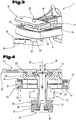
- Fig. 3 shows a detail of the adapter 1 according to Fig. 2 without a camera 2 secured onto the latter.
- the camera shoe mount 25 is represented here in a position that is partly detached from the clamping unit 24.
- a dovetail guide 29 is provided between these two parts.
- the recess corresponding to the dovetail guide 29 in the clamping unit 24 is closed off by a rear wall 30.
- the rear wall 30 thus functions as an end stop for the adjustment path of the camera shoe mount 25 along the guide formed by the dovetail guide 29.
- a prism-like plug 31 by means of which the camera shoe mount 25 is pushed downwards against the clamping unit 24 and thus clamped thereon.
- the activation of the plug 31 for clamping the camera shoe mount 25 is performed by pivoting a lever 32 from the "open” position ( Fig. 3 ) into the “closed” position ( Fig. 2 ), whereby the plug 31 is pulled downwards.
- Fig. 4 This functioning is illustrated by Fig. 4 described in the following.
- the hub of the lever 32 is thus supported in axial direction against a fixed threaded sleeve 33.
- Fig. 4 shows a detail of the adapter 1 according to Fig. 2 in cross section.
- the lever 32 is connected to the plug 31 for fixing the camera shoe mount 25 by a mandrel 34.
- oblique ramps are arranged, which slide onto one another during the pivoting of the lever 32. In this way when pivoting the lever 32 between the "open” and “closed” positions there is an axial displacement of the plug 31, the mandrel 34 and the lever 32 relative to the threaded sleeve 33.
- the hub of the lever 32 is secured by a screw 37 onto the mandrel 34, whereby between the screw 37 and the lever 32 a spring 38 is arranged, so that when clamping the plug 31 to clamp the camera shoe mount 25 a predefined force can be achieved.
- a pivotable bar 39 ( Fig. 2 ) is integrated, which can be brought into engagement with the stop 40 of the threaded sleeve 33, so that the lever 32 is secured in the "closed” position. Only by unlocking the bar 39 can the lever be pivoted into the "open” position and thus the clamping of the camera shoe mount 25 with the clamping unit 24 released.
- the threaded sleeve 33 is secured onto a clamping bolt 41, through which the mandrel 34 extends. At one end the clamping bolt 41 is connected to the clamping unit 24, whereby between the latter and a knurled nut 42 screwed onto the clamping bolt 41 the mechanical stage 23 is secured.
- the mechanical stage 23 comprises according to this exemplary embodiment a first mechanical stage plate 43 and a second mechanical stage plate 44, which are arranged like a sandwich on top of one another.
- mechanical stage guides 45, 46 are provided, the cross sections of which are designed to be complementary to the cross sections of the guiding tracks 26, 27 of the platform 6.
- the cross section of the first guiding track 26 and the complementary cross section of the first mechanical stage guide 45 are in the shape of a trapezium. This allows an automatic alignment of the mechanical stage 23 parallel to the first guiding track 26 and thus parallel to the sleeve axis 7.
- the second mechanical stage guide 46 and the complementary guiding track 27 of the platform 6 have a rectangular cross section.
- the guiding track 27 and the mechanical stage guide 46 thus have two degrees of freedom relative to one another, whereas the guiding track 26 and the mechanical stage guide 45 due to the trapezium shape have only one degree of freedom. This allows a reliable and precise alignment of the mechanical stage 26 relative to the platform 6.
- the mechanical stage plates 43, 44 can be moved towards one another and thus the mechanical stage 23 can be clamped onto the guiding tracks 26, 27 of the platform 6.
- the clamping unit 24 is also pushed against the mechanical stage 23. In this way a further displacement of the mechanical stage 23 along the guiding tracks 26, 27 as well as a lateral displacement of the clamping unit 24 with the camera shoe mount 25 is blocked at right angles to the direction of the guiding tracks 26, 27.
- two independently operating clamping devices are formed.
- the camera shoe mount 25 can be displaced along the dovetail guide 29 in the clamping unit 24 and removed from the latter.
- a clamping device is formed which acts on the platform 6, the mechanical stage 23 and the clamping unit 24. If the knurled screw 42 is loosened, the mechanical stage 23 in the platform 6 can be pushed forwards or backwards, and also the clamping unit 24 can be displaced in lateral direction relative to the mechanical stage 23.
- the thus independently operating clamping devices have the advantage that when removing the camera shoe mount 25 from the clamping unit 24 the settings of the mechanical stage 23 relative to the platform 6 remain saved.
- Fig. 5 shows the camera 2 with the camera shoe mount 25 secured thereonto in a view of the underside of the camera 2 in perspective.
- the camera shoe mount 25 is secured by the fastening screw 28 onto the camera 2, in that the fastening screw 28 is screwed to the support thread (not shown) of the camera 2.
- a second hole 47 is provided for the latter in the camera shoe mount 25, so that the screw connection can be achieved with the fastening screw 28 for different models of the camera 2 at different points of the camera shoe mount 25.
- the dovetail guide 29 of the camera shoe mount 25 is designed to be mirror-symmetrical relative to a middle plane 59.
- a cross section of the dovetail guide 29 relative to a cross sectional plane perpendicular to the longitudinal extension of the dovetail guide 29 ( Fig. 4 ) is mirror-symmetrical to the middle plane 59.
- the camera shoe mount 25 can be inserted in the position shown in Fig. 4 as well as in a position rotated 180° relative to the latter into the clamping unit 24 and can be fixed onto the latter.
- the position of the through hole 47 ( Fig. 4 ) projecting to the left the latter can thus also be arranged in a position projecting to the right.
- For the fastening screw 28 for securing to the support thread of the camera 2 thus a total of 3 different positions are available, which provide much greater flexibility or dimensional range with respect to the options for securing different models of cameras 2 or optical measuring devices.
- the camera shoe mount 25 also comprises locking mechanisms 48, 49 pretensioned by springs (not shown) in the underside of the dovetail guide 29.
- the locking mechanisms 48, 49 preferably comprise metal balls pretensioned by springs, which in the position fitted onto the clamping unit 24 ( Fig. 2 ), press into corresponding depressions in the clamping unit 24.
- the locking mechanisms 48, 49 thus prevent in the opened state, that is when the lever 32 is in the "open" position ( Fig. 3 ), the camera shoe mount 25 together with the camera 2 from sliding out of the dovetail guide 29 and thus prevent the camera 2 from falling to the ground.
- a noise indicates that the end position has been reached, which is caused by the balls of the locking mechanisms 48, 49 snapping into place.
- Fig. 6 shows the adapter 1 according to an alternative exemplary embodiment in perspective view.
- the base plate 5 with the sleeve 4 on the one hand and the platform 6 for the camera 2 are shown in a separated position.
- the base plate 5 and the sleeve 4 are located in a position pivoted by 180° relative to the position according to Fig. 1 and 2 .
- the sleeve 4 faces the camera shoe mount 25 secured to the clamping unit 24 or the mechanical stage 23.
- a distance reduced by about the length of the sleeve 4 of an eyepiece 16 pushed into the sleeve 4 is formed relative to the camera shoe mount 25 or a camera secured thereonto.
- the two guiding tracks 9, 10 of the base plate 5 are preferably designed to have an identically formed cross section. After removing the closing element 20 from the base plate 5 the latter can be separated from the platform 6 or its sliding members 11, 12 from the platform 6 and optionally reconnected in one of the two positions of the sleeve 4 shown in Figs. 2 and 6 to the platform 6.
- the base plate 5 is preferably designed to be symmetrical to a middle plane 50 perpendicular to the sleeve axis 7.
- connection of the sleeve 4 to the base plate 5 is released and thus removed from the side of the base plate 5 facing away from the camera 2 ( Fig. 1 ) and is refastened on the side of the base plate 5 facing the camera 2 ( Fig. 6 ).
- Fig. 7 shows an alternative exemplary embodiment of a camera shoe mount 25 for the adapter 1.
- Said camera shoe mount 25 comprises a plate-like basic body 51 with the dovetail guide 29 for securing onto the clamping unit 24 ( Fig. 2 , 3 ).
- a gear housing 52 sitting on the latter is securely connected to the basic body 51.
- the gear housing 52 there is a threaded spindle 53 aligned at right angles to the plate-like basic body 51, which spindle can be rotated with a spindle head 54.
- the camera shoe 25 according to this exemplary embodiment also comprises a plate-like clamping jaw 55 arranged parallel to the plate-like basic body 51.
- the clamping jaw 55 is connected to a sliding member 56 and is thus guided adjustable projecting laterally from the gear housing 52 in vertical direction.
- the sliding member 56 comprises a threaded hole (not shown), which is in engagement with the threaded spindle 53.
- clamping cushions 57, 58 are attached on the facing sides of the basic body 51 and the clamping jaw 55 .
- the camera shoe mount 25 according to this embodiment is used together with cameras which according to their form have no stative thread and thus are not secured onto the fastening screw 28 ( Fig. 1, 2 ). This includes for example many of the digital cameras with very small external dimensions but also for example mobile phones with integrated digital cameras.
- Fig. 8 shows a modified variant of the adapter 1 according to Fig. 7 with an integrated remote control 60. The latter is secured with its camera-side end to a plug housing 61 onto the clamping jaw 55 of the adapter 1.
- Fig. 9 shows a detail of the adapter 1 according to Fig. 8 in partial cross section.
- an elongated hole 62 is provided in the latter.
- On its inside the elongated hole 62 comprises a guide 63, on which the plug housing 61 can be displaced in lateral direction - according to double arrow 64 - and fixed in different positions.
- a trigger button 65 of the remote control 60 a plug 66 from the plug housing 61 can be moved downwards and thus the camera release 2 can be pressed.
- the plug housing 61 By adjusting the plug housing 61 in this way in the clamping jaw 55 the required alignment of the plug on the release of the camera 2 can also be achieved for differently designed cameras.
- the remote control 60 is formed by a cable trigger.
- electrically or pneumatically operated remote controls can be provided.
- a particular advantage of the adapter 1 according to the invention is the great flexibility in changing between different uses of the camera 2 on the one hand and also of the observation telescope on the other hand.
- the camera shoe mount 25 remains secured onto the camera 2
- the original adjustment of the optical axes 13, 15 of the camera objective 14 and the eyepiece 16 of the observation telescope can be rapidly returned to.
- the positions or settings of the platform 6 relative to the base plate 5 as well as the mechanical stage 23 relative to the platform 6 remain saved. This is because as in the known disassembly and assembly of the fastenings between the base plate 5 and the platform 6 also between the platform 6 and the mechanical stage 23 or the clamping unit 24 there is no change in the adjustment settings.
- the adapter 1 in the region of one of the guiding tracks 9, 10 and also in the region between one of the guiding tracks 26, 27 and the mechanical stage 23 and the adjacent area between the mechanical stage 23 and the clamping unit 24 scales (not shown) are provided. With the frequent use of the same camera 2 with the adapter 1 if there is an adjustment of the settings, for example when using a different camera 2, the original setting can be found again quickly and easily 2.
- helical gears (not shown) operating between the base plate 5 and the platform 6, between the platform 6 and the mechanical stage 23 and also between the mechanical stage 23 and the clamping unit 24 are provided, by means of which the adjustment can also be performed very precisely even with small adjustment movements along the guiding tacks.
Landscapes
- Physics & Mathematics (AREA)
- General Physics & Mathematics (AREA)
- Astronomy & Astrophysics (AREA)
- Optics & Photonics (AREA)
- Accessories Of Cameras (AREA)
- Telescopes (AREA)
Claims (13)
- Adapter (1) zur Befestigung eines Bildaufzeichnungsgeräts (2) oder eines optischen Messgeräts an einem Beobachtungsfernrohr (3), mit einem Podest (6) zur Befestigung des Bildaufzeichnungsgeräts (2) oder des Messgeräts und mit einer zylinderförmigen Hülse (4) zur Anbringung an oder zur Befestigung in einem Okular(16) des Beobachtungsfernrohrs (3), wobei die Hülse (4) an einer sich im rechten Winkel zu der Hülsenachse (7) erstreckenden Grundplatte (5) angeflanscht ist, wobei eine erste Führung auf der Grundplatte (5) vorgesehen ist, welche aus zwei ersten Führungsbahnen (9, 10) gebildet ist und rechtwinklig zu der Hülsenachse (7) verläuft, wobei das Podest (6) an der ersten Führung verstellbar ist, und wobei ein Kreuztisch (23) auf dem Podest (6) angeordnet ist, mit dem das Bildaufzeichnungsgerät (2) oder das Messgerät in einer parallel zu der Hülsenachse (7) verlaufenden parallelen Ebene verstellbar ist, wobei zwischen dem Podest (6) und dem Kreuztisch (23) eine zweite Führung (26, 27, 45, 46) ausgebildet ist, so dass der Kreuztisch (23) parallel zu der Hülsenachse (7) ausgerichtet werden kann, und dass der Kreuztisch (23) eine Spanneinheit (24) aufweist, die bezüglich des Kreuztisches (23) entlang dritter Führungsbahnen verstellbar ist, dadurch gekennzeichnet, dass ein Kameraschuh (25) abnehmbar mit der Spanneinheit (24) zur unmittelbaren Befestigung der Kamera (2) verbunden ist, wobei dritte Führungsbahnen, die zwischen der Spanneinheit (24) und dem Kreuztisch (23) ausgebildet sind, rechtwinklig zu der zweiten Führung (26, 27, 45, 46), die zwischen dem Kreuztisch (23) und dem Podest (6) ausgebildet ist, ausgerichtet sind, wobei die beiden ersten Führungsbahnen (9, 10) der Grundplatte (5) mit einem gleich geformten Querschnitt ausgebildet sind und symmetrisch zu einer zur Hülsenachse (7) senkrechten Mittelebene (50) sind.
- Adapter (1) nach Anspruch 1, dadurch gekennzeichnet, dass die Spanneinheit (24) rechtwinklig zu der Hülsenachse (7) und rechtwinklig zu der durch die ersten Führungsbahnen (9, 10) gebildeten ersten Führung verstellbar ist.
- Adapter (1) nach Anspruch 1 oder 2, dadurch gekennzeichnet, dass die zwischen dem Podest (6) und dem Kreuztisch (23) gebildete zweite Führung parallel zu der Hülsenachse (7) ausgerichtet ist, wobei das Podest (6) zwei zueinander parallel ausgerichtete zweite Führungsbahnen (26, 27) aufweist und auf dem Kreuztisch (23) zwei Kreuztischführungen (45, 46) ausgebildet sind, die mit den zweiten Führungsbahnen (26, 27) des Podests (6) in Eingriff stehen.
- Adapter (1) nach Anspruch 3, dadurch gekennzeichnet, dass in dem Podest (6) eine im Wesentlichen rechteckige, durchgehende Ausnehmung (22) ausgebildet ist und die zweiten Führungsbahnen (26, 27) in der Ausnehmung (22) des Podests (6) vorgesehen sind.
- Adapter (1) nach einem der vorhergehenden Ansprüche, dadurch gekennzeichnet, dass der Kameraschuh (25) und die Spanneinheit (24) eine erste Klemmvorrichtung aufweisen, mit der der Kameraschuh (25) an der Spanneinheit (24) festgeklemmt ist und der Kreuztisch (23), die Spanneinheit (24) und das Podest (6) eine zweite Klemmvorrichtung aufweisen, mit der sie relativ zueinander fixiert sind, wobei die erste Klemmvorrichtung unabhängig von der zweiten Klemmvorrichtung gelöst oder fixiert werden kann.
- Adapter (1) nach einem der vorhergehenden Ansprüche, dadurch gekennzeichnet, dass der Kameraschuh (25) einen plattenförmigen Grundkörper (51) und einen dazu parallel angeordneten plattenförmig ausgebildeten Klemmbacken (55) umfasst, wobei der Grundkörper (51) und der Klemmbacken (55) in ihrem relativen Abstand verstellbar sind.
- Adapter (1) nach Anspruch 6, dadurch gekennzeichnet, dass ein Fernauslöser (60) mit dem Klemmbacken (55) verbunden ist, wobei der Fernauslöser (60) auf ein Bildaufzeichnungsgerät (2) einwirken kann.
- Adapter (1) nach einem der vorhergehenden Ansprüche, dadurch gekennzeichnet, dass die Grundplatte (5) symmetrisch zu einer zur Hülsenachse (7) senkrechten Mittelebene (50) geformt ist.
- Verfahren zur Montage eines Bildaufzeichnungsgeräts (2) oder eines optischen Messgeräts an einem Beobachtungsfernrohr (3), wobei ein Adapter (1) mit einem Podest (6) und einer zylinderförmigen Hülse (4) angeordnet wird und wobei das Bildaufzeichnungsgerät (2) oder das Messgerät auf dem Podest (6) befestigt wird und ein Okular (16) des Beobachtungsfernrohrs (3) in der Hülse (4) aufgenommen oder befestigt wird, wobei die Hülse (4) an einer sich rechtwinklig zu einer Hülsenachse (7) erstreckenden Grundplatte (5) des Adapters (1) angeflanscht wird und das Podest (6) auf der Grundplatte (5) befestigt wird, wobei das Podest (6) an einer auf der Grundplatte (5) verlaufenden ersten Führung verstellt wird, und wobei ein Kreuztisch (23), an dem das Bildaufzeichnungsgerät (2) oder das Messgerät befestigt werden und der an dem Podest (6) befestigt ist, in einer zur Hülsenachse (7) parallel verlaufenden Ebene verstellt wird, wobei zwischen dem Podest (6) und dem Kreuztisch (23) eine zweite Führung (26, 27, 45, 46) ausgebildet ist und der Kreuztisch (23) parallel zu der Hülsenachse (7) ausgerichtet wird, und wobei eine Spanneinheit (24) auf dem Kreuztisch (23) angeordnet ist, die bezüglich des Kreuztisches (23) entlang dritter Führungsbahnen verstellbar ist, und dadurch gekennzeichnet, dass das Bildaufzeichnungsgerät (2) oder das Messgerät mit einem Kameraschuh (25) verbunden sind und der Kameraschuh (25) abnehmbar mit der Spanneinheit (24) verbunden ist, wobei die dritten Führungsbahnen, die zwischen der Spanneinheit (24) und dem Kreuztisch (23) ausgebildet sind, rechtwinklig zu der zweiten Führung, die zwischen dem Kreuztisch (23) und dem Podest (6) ausgebildet ist, ausgerichtet sind, und wobei die beiden ersten Führungsbahnen (9, 10) der Grundplatte (5) mit einem gleich geformten Querschnitt ausgebildet sind und symmetrisch zu einer zur Hülsenachse (7) senkrechten Mittelebene (50) sind.
- Verfahren nach Anspruch 9, dadurch gekennzeichnet, dass das Okular (16) aus der Hülse (4) und der Grundplatte (5) mit der Hülse (4) aus dem Podest (6) gelöst wird und die Grundplatte (5) dann um 180° gegenüber einer imaginären Achse geschwenkt wird, wobei die imaginäre Achse parallel zu einer Ausrichtungsrichtung der ersten Führung, die auf der Grundplatte (5) läuft, verläuft, und die Grundplatte (5) dann in das Podest (6) eingesetzt und befestigt wird.
- Verfahren nach Anspruch 9, dadurch gekennzeichnet, dass der das Bildaufzeichnungsgerät (2) oder das optische Messgerät tragende Kameraschuh (25) aus einer Spanneinheit (24) gelöst wird und der Kameraschuh (25) anschließend um 180° gegenüber einer imaginären Achse gedreht wird, wobei die imaginäre Achse parallel zu einer Ausrichtungsrichtung der ersten Führung, die auf der Grundplatte (5) läuft, verläuft, und der Kameraschuh (25) dann in die Spanneinheit (24) eingesetzt und darauf befestigt wird.
- Verfahren nach Anspruch 9, dadurch gekennzeichnet, dass der das Bildaufzeichnungsgerät (2) oder das optische Messgerät tragende Kameraschuh (25) aus der Spanneinheit (24) gelöst wird, während die Befestigung zwischen der Spanneinheit (24), dem Kreuztisch (23) und dem Podest (6) fixiert bleibt und so deren relative Positionierung gespeichert bleibt.
- Adapter (1) zur Befestigung eines Bildaufzeichnungsgeräts (2) oder eines optischen Messgeräts an einem Beobachtungsfernrohr (3), mit einem Podest (6) zur Befestigung des Bildaufzeichnungsgeräts (2) oder des Messgeräts und mit einer zylinderförmigen Hülse (4) zur Anbringung an oder zur Befestigung in einem Okular (16) des Beobachtungsfernrohrs (3), wobei die Hülse (4) an einer sich im rechten Winkel zu der Hülsenachse (7) erstreckenden Grundplatte (5) angeflanscht ist, wobei eine erste Führung auf der Grundplatte (5) vorgesehen ist, welche aus zwei ersten Führungsbahnen (9, 10) gebildet ist und rechtwinkelig zu der Hülsenachse (7) verläuft, wobei das Podest (6) an der ersten Führung verstellbar ist, und wobei ein Kreuztisch (23) auf dem Podest (6) angeordnet ist, mit dem das Bildaufzeichnungsgerät (2) oder das Messgerät in einer parallel zu der Hülsenachse (7) verlaufenden parallelen Ebene verstellbar ist, wobei der Kreuztisch (23) eine Spanneinheit (24) aufweist, die bezüglich des Kreuztisches (23) verstellbar ist, dadurch gekennzeichnet, dass ein Kameraschuh (25) abnehmbar mit der Spanneinheit (24) zur unmittelbaren Befestigung der Kamera (2) verbunden ist, und wobei der Kameraschuh (25) und die Spanneinheit (24) eine erste Klemmvorrichtung aufweisen, mit der der Kameraschuh (25) an der Spanneinheit (24) festgeklemmt ist, und der Kreuztisch (23), die Spanneinheit (24) und das Podest (6) eine zweite Klemmvorrichtung aufweisen, mit der sie relativ zueinander fixiert sind, wobei die erste Klemmvorrichtung unabhängig von der zweiten Klemmvorrichtung gelöst oder fixiert werden kann, wobei die beiden ersten Führungsbahnen (9, 10) der Grundplatte (5) mit einem gleich geformten Querschnitt ausgebildet sind und symmetrisch zu einer zur Hülsenachse (7) senkrechten Mittelebene (50) geformt sind.
Applications Claiming Priority (1)
| Application Number | Priority Date | Filing Date | Title |
|---|---|---|---|
| AT0191808A AT507542B1 (de) | 2008-12-10 | 2008-12-10 | Adapter für kamera und fernrohr |
Publications (2)
| Publication Number | Publication Date |
|---|---|
| EP2196848A1 EP2196848A1 (de) | 2010-06-16 |
| EP2196848B1 true EP2196848B1 (de) | 2017-01-18 |
Family
ID=41694749
Family Applications (1)
| Application Number | Title | Priority Date | Filing Date |
|---|---|---|---|
| EP09015296.8A Active EP2196848B1 (de) | 2008-12-10 | 2009-12-10 | Adapter für eine Kamera und ein Teleskop |
Country Status (3)
| Country | Link |
|---|---|
| US (1) | US8210757B2 (de) |
| EP (1) | EP2196848B1 (de) |
| AT (1) | AT507542B1 (de) |
Families Citing this family (18)
| Publication number | Priority date | Publication date | Assignee | Title |
|---|---|---|---|---|
| US8860789B1 (en) * | 2011-12-09 | 2014-10-14 | Vic G. Rice | Apparatus for producing three dimensional images |
| US20130230309A1 (en) * | 2012-03-02 | 2013-09-05 | Designport, Inc. | Optical scope couplers |
| US9624958B2 (en) * | 2012-09-11 | 2017-04-18 | Carson Optical, Inc. | Adaptor for connecting an electronic device having a camera to an optical device |
| US8661725B1 (en) * | 2012-10-01 | 2014-03-04 | Graflex, Inc. | Removably coupled boresight camera assembly for aligning weapons |
| US9097962B2 (en) * | 2012-10-04 | 2015-08-04 | Joseph M. JOHNSON, SR. | Extendible L-plate for camera equipment |
| US8842981B2 (en) * | 2013-02-08 | 2014-09-23 | HI Resolution Enterprises, LLC | Adapter for holding a camera-bearing device to an optical instrument |
| US9122131B2 (en) * | 2013-06-05 | 2015-09-01 | Iridex Corporation | Microscope observation tube smart-phone adaptor |
| US9253383B2 (en) * | 2013-08-08 | 2016-02-02 | Fl Archery Holdings Llc | Phone adapter for optical devices |
| US9179054B2 (en) * | 2013-12-02 | 2015-11-03 | Torrey Pines Logic, Inc. | Mountable, afocal adaptor for a camera |
| US9372383B2 (en) | 2014-03-14 | 2016-06-21 | Really Right Stuff, Llc | L-plate bracket for camera equipment |
| JP6452702B2 (ja) * | 2015-09-15 | 2019-01-16 | マイクロネット株式会社 | 携帯端末機取付アダプタ |
| US10160527B2 (en) * | 2017-01-23 | 2018-12-25 | Dongguan Longwell Sports Co., Ltd. | Diving goggles having detachable camera bracket |
| US10795146B2 (en) * | 2018-03-30 | 2020-10-06 | Celestron Acquisition, Llc | Smartphone adapter for imaging through optical devices |
| MX2022013582A (es) * | 2020-04-30 | 2023-02-27 | Dentiscope Inc | Periscopio montado en teléfono móvil y método que usa periscopio montado en teléfono móvil para diagnóstico dental remoto y automatizado. |
| US20220291573A1 (en) * | 2021-03-15 | 2022-09-15 | Chronos X LLC | Point of View Camera Mount |
| US12253664B2 (en) | 2021-03-19 | 2025-03-18 | Magview, Llc | Scope mount |
| JP2023158604A (ja) * | 2022-04-18 | 2023-10-30 | 萬里科技股▲分▼有限公司 | カメラレンズの回転リング用リニアクランプ式駆動機構 |
| CN120609322B (zh) * | 2025-08-11 | 2025-11-14 | 江苏润硕管业有限公司 | 一种塑料管件内径检测装置 |
Family Cites Families (10)
| Publication number | Priority date | Publication date | Assignee | Title |
|---|---|---|---|---|
| US4794414A (en) * | 1987-11-04 | 1988-12-27 | Kozina Daniel P | Universal camera actuator bracket |
| JPH1090753A (ja) * | 1996-09-02 | 1998-04-10 | Shokin An | カメラにフィルタを装着する装置 |
| US6196504B1 (en) * | 1998-07-09 | 2001-03-06 | Maurice W. Lemke | Positive-lock-and-release device for camera mounting |
| US20020197075A1 (en) * | 2000-12-19 | 2002-12-26 | Crockett Richard L. | Eyepiece to instrument coupler |
| US6717727B2 (en) * | 2001-02-16 | 2004-04-06 | Samuel W. Barziza | Universal camera mounting adapter and method |
| ATE337536T1 (de) * | 2003-05-14 | 2006-09-15 | Swarovski Optik Kg | Vorrichtung zur befestigung einer kamera an einem beobachtungsfernrohr |
| US7077582B2 (en) * | 2003-08-20 | 2006-07-18 | Johnson Joseph M | Quick-release clamp for photographic equipment |
| TWI234684B (en) * | 2004-03-29 | 2005-06-21 | Long Perng Co Ltd | Optical equipment converter |
| JP4606123B2 (ja) * | 2004-10-29 | 2011-01-05 | 株式会社デジスコドットコム | アイカップ兼望遠鏡側アダプタ並びにこれを備えたアイピース及び望遠鏡 |
| US7088918B1 (en) * | 2005-01-21 | 2006-08-08 | Leica Microsystems (Schweiz) Ag | Mounting device for a camera with automatic exposure mode to an optical system |
-
2008
- 2008-12-10 AT AT0191808A patent/AT507542B1/de not_active IP Right Cessation
-
2009
- 2009-12-10 US US12/635,074 patent/US8210757B2/en not_active Expired - Fee Related
- 2009-12-10 EP EP09015296.8A patent/EP2196848B1/de active Active
Non-Patent Citations (1)
| Title |
|---|
| None * |
Also Published As
| Publication number | Publication date |
|---|---|
| US8210757B2 (en) | 2012-07-03 |
| AT507542A1 (de) | 2010-05-15 |
| EP2196848A1 (de) | 2010-06-16 |
| AT507542B1 (de) | 2010-11-15 |
| US20100142036A1 (en) | 2010-06-10 |
Similar Documents
| Publication | Publication Date | Title |
|---|---|---|
| EP2196848B1 (de) | Adapter für eine Kamera und ein Teleskop | |
| CN110320659B (zh) | 用于通过光学装置进行成像的智能手机配接器 | |
| EP1403678B1 (de) | Vorrichtung zum Halten einer Kamera hinter einem Fernglas | |
| US5862428A (en) | Apparatus for detachably mounting a lens filter onto a camera | |
| EP1477763B2 (de) | Vorrichtung zur Befestigung einer Kamera an einem Beobachtungsfernrohr | |
| US20220054099A1 (en) | X-ray detector holder stand | |
| US20060143764A1 (en) | Method and apparatus for mounting a vision system | |
| US9657887B2 (en) | Device for the stable and zero backlash adjustment of a camera-holding device around at least one tilting axis | |
| US6476963B1 (en) | Photographic binocular | |
| US6717727B2 (en) | Universal camera mounting adapter and method | |
| EP3559536B1 (de) | Kamerasteuerungsverfahren und vorrichtung | |
| JP2010266582A (ja) | 光学素子の位置決め装置 | |
| JP2017527839A (ja) | 単眼式立体カメラ | |
| US12130421B2 (en) | Folding smartphone adapter for imaging through optical devices | |
| US20070109635A1 (en) | Device for fastening imaging units on an observing telescope | |
| JP3291796B2 (ja) | カメラとオプションレンズとの取付け支持具 | |
| EP0197544A1 (de) | Fernsehkamera zur Aussenüberwachung | |
| DE19839218A1 (de) | Froschperspektiven-Griffvorrichtung für eine elektronische Nachrichten-Aufnahme-Kamera | |
| US4350419A (en) | Front projection photographic apparatus | |
| CN216052417U (zh) | 一种可上下调节的手机拍照架结构 | |
| JP2006128847A (ja) | ハンディー型ビデオカメラ装置 | |
| EP3420411B1 (de) | Vorrichtung zur verwendung und gleichzeitig unterstützung von mehr als einer kamera | |
| DE102013218098A1 (de) | Elektronische Kamera | |
| US20030189752A1 (en) | Portable optical device | |
| JP3974266B2 (ja) | ファインダ光軸調整機構 |
Legal Events
| Date | Code | Title | Description |
|---|---|---|---|
| PUAI | Public reference made under article 153(3) epc to a published international application that has entered the european phase |
Free format text: ORIGINAL CODE: 0009012 |
|
| AK | Designated contracting states |
Kind code of ref document: A1 Designated state(s): AT BE BG CH CY CZ DE DK EE ES FI FR GB GR HR HU IE IS IT LI LT LU LV MC MK MT NL NO PL PT RO SE SI SK SM TR |
|
| AX | Request for extension of the european patent |
Extension state: AL BA RS |
|
| 17P | Request for examination filed |
Effective date: 20101216 |
|
| 17Q | First examination report despatched |
Effective date: 20131011 |
|
| GRAP | Despatch of communication of intention to grant a patent |
Free format text: ORIGINAL CODE: EPIDOSNIGR1 |
|
| RIC1 | Information provided on ipc code assigned before grant |
Ipc: G03B 17/14 20060101ALI20160415BHEP Ipc: G03B 5/00 20060101ALI20160415BHEP Ipc: G03B 17/56 20060101AFI20160415BHEP Ipc: G03B 17/48 20060101ALI20160415BHEP Ipc: G02B 23/16 20060101ALI20160415BHEP |
|
| INTG | Intention to grant announced |
Effective date: 20160519 |
|
| GRAJ | Information related to disapproval of communication of intention to grant by the applicant or resumption of examination proceedings by the epo deleted |
Free format text: ORIGINAL CODE: EPIDOSDIGR1 |
|
| GRAS | Grant fee paid |
Free format text: ORIGINAL CODE: EPIDOSNIGR3 |
|
| GRAP | Despatch of communication of intention to grant a patent |
Free format text: ORIGINAL CODE: EPIDOSNIGR1 |
|
| INTC | Intention to grant announced (deleted) | ||
| RAP1 | Party data changed (applicant data changed or rights of an application transferred) |
Owner name: SWAROVSKI-OPTIK KG |
|
| INTG | Intention to grant announced |
Effective date: 20161026 |
|
| GRAA | (expected) grant |
Free format text: ORIGINAL CODE: 0009210 |
|
| AK | Designated contracting states |
Kind code of ref document: B1 Designated state(s): AT BE BG CH CY CZ DE DK EE ES FI FR GB GR HR HU IE IS IT LI LT LU LV MC MK MT NL NO PL PT RO SE SI SK SM TR |
|
| REG | Reference to a national code |
Ref country code: GB Ref legal event code: FG4D |
|
| REG | Reference to a national code |
Ref country code: CH Ref legal event code: EP |
|
| REG | Reference to a national code |
Ref country code: AT Ref legal event code: REF Ref document number: 863240 Country of ref document: AT Kind code of ref document: T Effective date: 20170215 |
|
| REG | Reference to a national code |
Ref country code: IE Ref legal event code: FG4D |
|
| REG | Reference to a national code |
Ref country code: DE Ref legal event code: R096 Ref document number: 602009043801 Country of ref document: DE |
|
| REG | Reference to a national code |
Ref country code: NL Ref legal event code: MP Effective date: 20170118 |
|
| REG | Reference to a national code |
Ref country code: LT Ref legal event code: MG4D |
|
| PG25 | Lapsed in a contracting state [announced via postgrant information from national office to epo] |
Ref country code: NL Free format text: LAPSE BECAUSE OF FAILURE TO SUBMIT A TRANSLATION OF THE DESCRIPTION OR TO PAY THE FEE WITHIN THE PRESCRIBED TIME-LIMIT Effective date: 20170118 |
|
| PG25 | Lapsed in a contracting state [announced via postgrant information from national office to epo] |
Ref country code: GR Free format text: LAPSE BECAUSE OF FAILURE TO SUBMIT A TRANSLATION OF THE DESCRIPTION OR TO PAY THE FEE WITHIN THE PRESCRIBED TIME-LIMIT Effective date: 20170419 Ref country code: HR Free format text: LAPSE BECAUSE OF FAILURE TO SUBMIT A TRANSLATION OF THE DESCRIPTION OR TO PAY THE FEE WITHIN THE PRESCRIBED TIME-LIMIT Effective date: 20170118 Ref country code: NO Free format text: LAPSE BECAUSE OF FAILURE TO SUBMIT A TRANSLATION OF THE DESCRIPTION OR TO PAY THE FEE WITHIN THE PRESCRIBED TIME-LIMIT Effective date: 20170418 Ref country code: IS Free format text: LAPSE BECAUSE OF FAILURE TO SUBMIT A TRANSLATION OF THE DESCRIPTION OR TO PAY THE FEE WITHIN THE PRESCRIBED TIME-LIMIT Effective date: 20170518 Ref country code: LT Free format text: LAPSE BECAUSE OF FAILURE TO SUBMIT A TRANSLATION OF THE DESCRIPTION OR TO PAY THE FEE WITHIN THE PRESCRIBED TIME-LIMIT Effective date: 20170118 Ref country code: FI Free format text: LAPSE BECAUSE OF FAILURE TO SUBMIT A TRANSLATION OF THE DESCRIPTION OR TO PAY THE FEE WITHIN THE PRESCRIBED TIME-LIMIT Effective date: 20170118 |
|
| PG25 | Lapsed in a contracting state [announced via postgrant information from national office to epo] |
Ref country code: BG Free format text: LAPSE BECAUSE OF FAILURE TO SUBMIT A TRANSLATION OF THE DESCRIPTION OR TO PAY THE FEE WITHIN THE PRESCRIBED TIME-LIMIT Effective date: 20170418 Ref country code: PL Free format text: LAPSE BECAUSE OF FAILURE TO SUBMIT A TRANSLATION OF THE DESCRIPTION OR TO PAY THE FEE WITHIN THE PRESCRIBED TIME-LIMIT Effective date: 20170118 Ref country code: SE Free format text: LAPSE BECAUSE OF FAILURE TO SUBMIT A TRANSLATION OF THE DESCRIPTION OR TO PAY THE FEE WITHIN THE PRESCRIBED TIME-LIMIT Effective date: 20170118 Ref country code: LV Free format text: LAPSE BECAUSE OF FAILURE TO SUBMIT A TRANSLATION OF THE DESCRIPTION OR TO PAY THE FEE WITHIN THE PRESCRIBED TIME-LIMIT Effective date: 20170118 Ref country code: PT Free format text: LAPSE BECAUSE OF FAILURE TO SUBMIT A TRANSLATION OF THE DESCRIPTION OR TO PAY THE FEE WITHIN THE PRESCRIBED TIME-LIMIT Effective date: 20170518 Ref country code: ES Free format text: LAPSE BECAUSE OF FAILURE TO SUBMIT A TRANSLATION OF THE DESCRIPTION OR TO PAY THE FEE WITHIN THE PRESCRIBED TIME-LIMIT Effective date: 20170118 |
|
| REG | Reference to a national code |
Ref country code: DE Ref legal event code: R097 Ref document number: 602009043801 Country of ref document: DE |
|
| PG25 | Lapsed in a contracting state [announced via postgrant information from national office to epo] |
Ref country code: EE Free format text: LAPSE BECAUSE OF FAILURE TO SUBMIT A TRANSLATION OF THE DESCRIPTION OR TO PAY THE FEE WITHIN THE PRESCRIBED TIME-LIMIT Effective date: 20170118 Ref country code: IT Free format text: LAPSE BECAUSE OF FAILURE TO SUBMIT A TRANSLATION OF THE DESCRIPTION OR TO PAY THE FEE WITHIN THE PRESCRIBED TIME-LIMIT Effective date: 20170118 Ref country code: RO Free format text: LAPSE BECAUSE OF FAILURE TO SUBMIT A TRANSLATION OF THE DESCRIPTION OR TO PAY THE FEE WITHIN THE PRESCRIBED TIME-LIMIT Effective date: 20170118 Ref country code: SK Free format text: LAPSE BECAUSE OF FAILURE TO SUBMIT A TRANSLATION OF THE DESCRIPTION OR TO PAY THE FEE WITHIN THE PRESCRIBED TIME-LIMIT Effective date: 20170118 |
|
| PLBE | No opposition filed within time limit |
Free format text: ORIGINAL CODE: 0009261 |
|
| STAA | Information on the status of an ep patent application or granted ep patent |
Free format text: STATUS: NO OPPOSITION FILED WITHIN TIME LIMIT |
|
| REG | Reference to a national code |
Ref country code: FR Ref legal event code: PLFP Year of fee payment: 9 |
|
| PG25 | Lapsed in a contracting state [announced via postgrant information from national office to epo] |
Ref country code: SM Free format text: LAPSE BECAUSE OF FAILURE TO SUBMIT A TRANSLATION OF THE DESCRIPTION OR TO PAY THE FEE WITHIN THE PRESCRIBED TIME-LIMIT Effective date: 20170118 Ref country code: DK Free format text: LAPSE BECAUSE OF FAILURE TO SUBMIT A TRANSLATION OF THE DESCRIPTION OR TO PAY THE FEE WITHIN THE PRESCRIBED TIME-LIMIT Effective date: 20170118 |
|
| 26N | No opposition filed |
Effective date: 20171019 |
|
| PG25 | Lapsed in a contracting state [announced via postgrant information from national office to epo] |
Ref country code: SI Free format text: LAPSE BECAUSE OF FAILURE TO SUBMIT A TRANSLATION OF THE DESCRIPTION OR TO PAY THE FEE WITHIN THE PRESCRIBED TIME-LIMIT Effective date: 20170118 |
|
| REG | Reference to a national code |
Ref country code: DE Ref legal event code: R082 Ref document number: 602009043801 Country of ref document: DE Representative=s name: ABP BURGER RECHTSANWALTSGESELLSCHAFT MBH, DE |
|
| REG | Reference to a national code |
Ref country code: CH Ref legal event code: PL |
|
| REG | Reference to a national code |
Ref country code: IE Ref legal event code: MM4A |
|
| PG25 | Lapsed in a contracting state [announced via postgrant information from national office to epo] |
Ref country code: LU Free format text: LAPSE BECAUSE OF NON-PAYMENT OF DUE FEES Effective date: 20171210 Ref country code: MT Free format text: LAPSE BECAUSE OF NON-PAYMENT OF DUE FEES Effective date: 20171210 |
|
| REG | Reference to a national code |
Ref country code: BE Ref legal event code: MM Effective date: 20171231 |
|
| REG | Reference to a national code |
Ref country code: FR Ref legal event code: PLFP Year of fee payment: 10 |
|
| PG25 | Lapsed in a contracting state [announced via postgrant information from national office to epo] |
Ref country code: IE Free format text: LAPSE BECAUSE OF NON-PAYMENT OF DUE FEES Effective date: 20171210 |
|
| PG25 | Lapsed in a contracting state [announced via postgrant information from national office to epo] |
Ref country code: LI Free format text: LAPSE BECAUSE OF NON-PAYMENT OF DUE FEES Effective date: 20171231 Ref country code: BE Free format text: LAPSE BECAUSE OF NON-PAYMENT OF DUE FEES Effective date: 20171231 Ref country code: CH Free format text: LAPSE BECAUSE OF NON-PAYMENT OF DUE FEES Effective date: 20171231 |
|
| PGFP | Annual fee paid to national office [announced via postgrant information from national office to epo] |
Ref country code: FR Payment date: 20181024 Year of fee payment: 10 |
|
| PG25 | Lapsed in a contracting state [announced via postgrant information from national office to epo] |
Ref country code: MC Free format text: LAPSE BECAUSE OF FAILURE TO SUBMIT A TRANSLATION OF THE DESCRIPTION OR TO PAY THE FEE WITHIN THE PRESCRIBED TIME-LIMIT Effective date: 20170118 Ref country code: HU Free format text: LAPSE BECAUSE OF FAILURE TO SUBMIT A TRANSLATION OF THE DESCRIPTION OR TO PAY THE FEE WITHIN THE PRESCRIBED TIME-LIMIT; INVALID AB INITIO Effective date: 20091210 |
|
| REG | Reference to a national code |
Ref country code: AT Ref legal event code: UEP Ref document number: 863240 Country of ref document: AT Kind code of ref document: T Effective date: 20170118 |
|
| PG25 | Lapsed in a contracting state [announced via postgrant information from national office to epo] |
Ref country code: CY Free format text: LAPSE BECAUSE OF NON-PAYMENT OF DUE FEES Effective date: 20170118 |
|
| PG25 | Lapsed in a contracting state [announced via postgrant information from national office to epo] |
Ref country code: MK Free format text: LAPSE BECAUSE OF FAILURE TO SUBMIT A TRANSLATION OF THE DESCRIPTION OR TO PAY THE FEE WITHIN THE PRESCRIBED TIME-LIMIT Effective date: 20170118 |
|
| PG25 | Lapsed in a contracting state [announced via postgrant information from national office to epo] |
Ref country code: TR Free format text: LAPSE BECAUSE OF FAILURE TO SUBMIT A TRANSLATION OF THE DESCRIPTION OR TO PAY THE FEE WITHIN THE PRESCRIBED TIME-LIMIT Effective date: 20170118 |
|
| PGFP | Annual fee paid to national office [announced via postgrant information from national office to epo] |
Ref country code: AT Payment date: 20191127 Year of fee payment: 11 |
|
| PG25 | Lapsed in a contracting state [announced via postgrant information from national office to epo] |
Ref country code: FR Free format text: LAPSE BECAUSE OF NON-PAYMENT OF DUE FEES Effective date: 20191231 |
|
| PGFP | Annual fee paid to national office [announced via postgrant information from national office to epo] |
Ref country code: GB Payment date: 20201014 Year of fee payment: 12 |
|
| REG | Reference to a national code |
Ref country code: AT Ref legal event code: MM01 Ref document number: 863240 Country of ref document: AT Kind code of ref document: T Effective date: 20201210 |
|
| PG25 | Lapsed in a contracting state [announced via postgrant information from national office to epo] |
Ref country code: AT Free format text: LAPSE BECAUSE OF NON-PAYMENT OF DUE FEES Effective date: 20201210 |
|
| GBPC | Gb: european patent ceased through non-payment of renewal fee |
Effective date: 20211210 |
|
| PG25 | Lapsed in a contracting state [announced via postgrant information from national office to epo] |
Ref country code: GB Free format text: LAPSE BECAUSE OF NON-PAYMENT OF DUE FEES Effective date: 20211210 |
|
| REG | Reference to a national code |
Ref country code: DE Ref legal event code: R081 Ref document number: 602009043801 Country of ref document: DE Owner name: SWAROVSKI-OPTIK AG & CO KG., AT Free format text: FORMER OWNER: SWAROVSKI-OPTIK KG, ABSAM, AT |
|
| PGFP | Annual fee paid to national office [announced via postgrant information from national office to epo] |
Ref country code: CZ Payment date: 20221024 Year of fee payment: 14 |
|
| PG25 | Lapsed in a contracting state [announced via postgrant information from national office to epo] |
Ref country code: CZ Free format text: LAPSE BECAUSE OF NON-PAYMENT OF DUE FEES Effective date: 20231210 |
|
| PG25 | Lapsed in a contracting state [announced via postgrant information from national office to epo] |
Ref country code: CZ Free format text: LAPSE BECAUSE OF NON-PAYMENT OF DUE FEES Effective date: 20231210 |
|
| PGFP | Annual fee paid to national office [announced via postgrant information from national office to epo] |
Ref country code: DE Payment date: 20241218 Year of fee payment: 16 |