EP2197199A2 - Caméra à imagerie thermique et procédé de construction d'une image thermographique - Google Patents
Caméra à imagerie thermique et procédé de construction d'une image thermographique Download PDFInfo
- Publication number
- EP2197199A2 EP2197199A2 EP09015237A EP09015237A EP2197199A2 EP 2197199 A2 EP2197199 A2 EP 2197199A2 EP 09015237 A EP09015237 A EP 09015237A EP 09015237 A EP09015237 A EP 09015237A EP 2197199 A2 EP2197199 A2 EP 2197199A2
- Authority
- EP
- European Patent Office
- Prior art keywords
- image
- thermal imaging
- imaging camera
- acquired
- thermographic
- Prior art date
- Legal status (The legal status is an assumption and is not a legal conclusion. Google has not performed a legal analysis and makes no representation as to the accuracy of the status listed.)
- Granted
Links
Images




Classifications
-
- H—ELECTRICITY
- H04—ELECTRIC COMMUNICATION TECHNIQUE
- H04N—PICTORIAL COMMUNICATION, e.g. TELEVISION
- H04N23/00—Cameras or camera modules comprising electronic image sensors; Control thereof
- H04N23/60—Control of cameras or camera modules
- H04N23/63—Control of cameras or camera modules by using electronic viewfinders
-
- H—ELECTRICITY
- H04—ELECTRIC COMMUNICATION TECHNIQUE
- H04N—PICTORIAL COMMUNICATION, e.g. TELEVISION
- H04N23/00—Cameras or camera modules comprising electronic image sensors; Control thereof
- H04N23/10—Cameras or camera modules comprising electronic image sensors; Control thereof for generating image signals from different wavelengths
- H04N23/11—Cameras or camera modules comprising electronic image sensors; Control thereof for generating image signals from different wavelengths for generating image signals from visible and infrared light wavelengths
-
- H—ELECTRICITY
- H04—ELECTRIC COMMUNICATION TECHNIQUE
- H04N—PICTORIAL COMMUNICATION, e.g. TELEVISION
- H04N23/00—Cameras or camera modules comprising electronic image sensors; Control thereof
- H04N23/20—Cameras or camera modules comprising electronic image sensors; Control thereof for generating image signals from infrared radiation only
- H04N23/23—Cameras or camera modules comprising electronic image sensors; Control thereof for generating image signals from infrared radiation only from thermal infrared radiation
-
- H—ELECTRICITY
- H04—ELECTRIC COMMUNICATION TECHNIQUE
- H04N—PICTORIAL COMMUNICATION, e.g. TELEVISION
- H04N23/00—Cameras or camera modules comprising electronic image sensors; Control thereof
- H04N23/60—Control of cameras or camera modules
- H04N23/698—Control of cameras or camera modules for achieving an enlarged field of view, e.g. panoramic image capture
-
- G—PHYSICS
- G01—MEASURING; TESTING
- G01J—MEASUREMENT OF INTENSITY, VELOCITY, SPECTRAL CONTENT, POLARISATION, PHASE OR PULSE CHARACTERISTICS OF INFRARED, VISIBLE OR ULTRAVIOLET LIGHT; COLORIMETRY; RADIATION PYROMETRY
- G01J5/00—Radiation pyrometry, e.g. infrared or optical thermometry
- G01J2005/0077—Imaging
-
- H—ELECTRICITY
- H04—ELECTRIC COMMUNICATION TECHNIQUE
- H04N—PICTORIAL COMMUNICATION, e.g. TELEVISION
- H04N23/00—Cameras or camera modules comprising electronic image sensors; Control thereof
- H04N23/60—Control of cameras or camera modules
- H04N23/69—Control of means for changing angle of the field of view, e.g. optical zoom objectives or electronic zooming
Definitions
- the invention relates to a thermal imaging camera for taking thermographic images of a measurement object in the infrared region with an indicator tool built in or on the housing for a false color representation of the taken thermographic images, where the thermal imaging camera is made as a hand-held unit.
- the representation of the thermographic images may use any kind of color mapping, e.g. false color representation, grey tone representation.
- the invention additionally relates to a method for generating a thermographic image of a large measurement object.
- a system for dual band acquisition of infrared images in which the IR images acquired in two spectral bands are combined into an image by overlapping by means of image processing in a computer system is known from the publication of M. Muller et al.: "Real-time image processing and fusion for a new high-speed dual-band infrared camera.”
- a digital photo apparatus for taking images in the visible spectral region in which an objective head is designed so that it can rotate in manual or automatic mode on the housing is known from DE 203 05 457 U1 .
- a digital camera for taking images in the visible spectral region in which a one-dimensional panoramic image can be generated is known from US 2005/0206743 A1 .
- thermographic images are frequently used to take thermographic images, thus images optically acquired in the infrared spectral region, in which temperature information obtained from the images taken of structures or parts of structures is represented in a false color representation, thus by means of a false color scale, or by brightness scales, or grey scales. From the thermographic images it is possible to obtain, among other things, information about the building's condition, such as condition of insulation, water damage and/or mold damage, and also for surveillance of room areas and for monitoring or control of manufacturing processes.
- the invention is based on the task of creating a thermal imaging camera that enables the acquisition and display of large solid angle regions with high resolution.
- the invention proposes a solution to this problem by providing a thermal imaging camera with the features of claim 1 and a method according to claim 11.
- Advantageous features are described in the dependent claims and the description of embodiments of the invention.
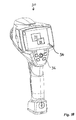
- Figures 1A and 1B provide an example of a thermal imaging camera 30 for use with the invention provided herein.
- an electronic evaluation unit 80 (cf. the sectional view of the thermal imaging camera 30 in Fig. 8 ) is integrated into the thermal imaging camera 30 of the kind mentioned at the start, with which at least an acquired thermographic image 32 can be stitched with another acquired thermographic image 32 or a stored thermographic image in the edge regions, where the images each repeat the same section of the measurement object in said edge region, to form a new thermographic overall image and can be provided for combined display with the display tool 34, where the display tool 34 has a zoom function 36 for free selection of a segment of the overall image that is to be enlarged.
- the measurement object specifies a solid angle region for an overall image, which is minimally divided into partial solid angle regions, where each partial solid angle region corresponds with sufficient overlap to an image to be acquired, and the acquired images 32 are combined into the overall image at the overlappings where they have a corresponding content. It is advantageous in this case that with each additionally acquired image 32, a new overall image can be generated in the thermal imaging camera and the resolution of said image is not limited by the size of the overall image.
- a thermal imaging camera is available with which large areas, for example, a building or an industrial plant or a landscape, can be photographed with high resolution, and the focal plane array needs only low resolution, so the manufacturing costs of the thermal imaging camera 30 are considerably reduced.
- Figure 2 provides an example of an overall image 50 of the sensor fields taken with the thermal imaging camera 30.
- the display tool 34 also needs not have to have high requirements with regard to maximum possible resolution of the presentation if the display tool 34 is provided with controls for scrolling and/or zooming 36 (e.g., buttons, joysticks, touch pads) the displayed image.
- controls for scrolling and/or zooming 36 e.g., buttons, joysticks, touch pads
- the thermal imaging camera 30 that has been developed in this way is thus especially suitable for the requirements of building thermography.
- a thermal imaging camera 30 that can be used in one-hand operation because of its compact size, for example, at construction sites, is made available with the invention.
- the evaluation unit 80 contains an image recognition tool, with which partial areas with corresponding content can be identified when there is a number of acquired images 32.
- an image recognition tool is integrated into electronic evaluation unit 80.
- Figure 2 shows an object 49 to be at least partially imaged.
- Figure 3 shows overlapped acquired images 32 (32a, 32b, 32c, 32d, 32e) taken of portions of the object 49 identified by the image recognition tool, which may be displayed on the display tool 34.
- the invention takes advantage of the finding that the computational capacity necessary for identification of the corresponding partial regions at which the images are stitched together can be integrated into the thermal imaging camera 30.
- the acquired images 32 are designated as images 1-20, although, as will be appreciated by those skilled in the art, any number of the images 32 may be utilized.
- points, lines, edges and/or structures marked with the image recognition tool can be identified. These identified marked points, lines, edges and/or structures do not necessarily correspond to points, lines, edges and/or structures of an image obtained in the visible spectral range and can be used for identification of the corresponding partial regions. More generally, the image recognition tool may be constructed such that it allows to identify image features such as SURF, SIFT or other transformation invariant features that may not necessarily be recognizable to the bare eye.
- An advantageous embodiment of the invention can provide that partial regions in different images with corresponding content (i.e., identical or substantially similar content) in the horizontal and/or vertical edge regions of the thermographic images can be identified. In this manner, same image regions between different of the acquired images 32 may be identified. It is advantageous in this case that not only a panoramic image, as is well known, for example, in landscape photography, but also an image composed in two dimensions, width and height, can be generated, as is advantageous for the photography of buildings and industrial plants and the like.
- the evaluation unit 80 has a tool for pattern recognition.
- a pattern recognition tool is integrated into electronic evaluation unit 80.
- a triggering tool 40 is made, through the actuation of which an additional thermographic image can be taken.
- the camera is merely aimed at the last segment of the overall region to be photographed and a new image can be produced by means of the triggering tool 40 and the stored, and combined with the already acquired images 32.
- the display tool 34 of the thermal imaging camera 30 show a timewise continuous image taken in the visible and/or infrared spectral regions. In this way, a swiveling of the thermal imaging camera 30 to a new position can be monitored in the display tool 34 when using the camera 30.
- the enlargement scale of the display is automatically matched to the size of the current overall image 50.
- thermographic image acquired in the infrared region results when the display can simultaneously show the thermographic image acquired in the infrared region and an image acquired in the visible spectral region.
- a display of this kind can take place, for example, by overlapping the images, or by separate presentation in separate windows, or separate displays.
- thermographic image and the image taken in the visible spectral region can be represented on top of one another and/or overlapping and/or at least partially covering one another and/or fused using ⁇ -blending (alpha-blending), so that corresponding image segments from the same parts of the measurement object can be represented at the same site of the display tool 34 and/or in the same display scale.
- Figure 3 provides an example of an IR image 52 with five acquired images 32a, 32b, 32c, 32d, 32e, as identified by the image recognition tool, overlapping.
- the segment of the object photographed is preselected by the user and shown on the display as a black frame.
- FIG. 5 illustrates an image with brush-tool-like stitching of the boxes 1-20.
- a motion sensor may be used to detect the swivelling motion of the camera 30.
- the swivelling motion is calculated using feature and/or pattern detection algorithms by comparing subsequent thermal images 32 of the acquired sequence in real time.
- low distortion stripes 72, 74 from the image streams are used to improve the overall look and feel of the stitched image, as shown in Figure 6 (70).
- Thermal imaging systems/cameras 30 tend to be afflicted with optical distortions that are mostly caused by the optical lenses. Due to these so called barrel or pincushion distortions, the process of stitching acquired images 32 together to obtain one overall image 50 gets profoundly more complex and computationally expensive. To provide good stitching results it is of essence to remove this distortion field and therefore correct the geometry of the acquired image(s) 32. Using un-corrected images results in loss of detail and accuracy.
- This problem scales with the number of acquired images 32 that are going to be stitched together and is therefore provides an unwanted obstacle to inevitable for a video stitching approach where the imaging camera 30 is swiveled over the scene.
- This distortion correction has to be done in real-time and therefore, increases the overall costs of the computing unit due to its complexity.
- the present invention provides a way to avoid this time consuming process and present a real-time video stitching approach for infrared imaging camera devices that is highly scalable and computationally frugal.
- Our approach takes into account, that the most common distortions that are caused by the shortcomings of low priced optical systems increase their effect on the image depending on the pixel distance of the center of the optical system. This means that there are regions in the acquired images with almost no distortion that could intervene in the stitching process.
- the approach of the present invention identifies these regions, either manually or automatically and provides an area where information for the stitching process can be taken without the need to apply a distortion correction to the overall image 50. Having identified this sub-region of the overall image 50 the motion between two or more consecutive frames is determined.
- the motion determination process is either performed by correlation (cross correlation, normalized cross correlation (CCF/NCCF)), motion filters (Kalman-Filter, etc.), feature-based (SIFT, SURF, LOG, etc.) approaches or motion sensors that provide the needed accuracy. Having determined the actual vector that describes the motion of consecutive frames the new image parts can be determined and added to the overall image 50.
- the imaging system takes many acquired images 32 per second and the swiveling motion of the user is typically small according to the number of frames per second, the movement from one to another pixel is quite small so that there will be a tight information cloud extracted out of the frame sequence that improves the result of the overall image 50 even more.
- the information extracted may be used in the stitching process to obtain the overall image 50 with a temporal noise reduction that is simply done by weighting the addition of the frame parts that are transferred into the overall image 50.
- This process of intelligent combination of the partial images not only results in a comprehensive overall image 50 with all information of the acquired frame sequence in it but also enhances the signal to noise ratio by filtering noise in the temporal domain.
- Swiveling the imaging device over the scene to acquire a frame sequence with which the overall image 50 will be computed one gathers a new problem class that's concerning the image acquisition at different viewpoints.
- Images taken at different viewpoints from scenes where visible objects differ in their distance to the spectator (imaging device) show deformations in consecutive frames that can't be modeled by simple linear deformation models, such as translation and rotation. By combining such images, the overlap area may not include enough comparable information to computer an overall image 50 with no artifacts.
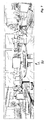
- Figure 7 show the result of the application of the embodiment described above to a 3D scene 80 with objects in different distances from the camera 30.
- the stitching causes distortions to the image, but provides a mechanism that works well for limiting the distortion using the almost undistorted distortion stripes 72, 74. Therefore, the 3D scene is created using acquired images 32.
- the sensor signals of the motion sensor can be detected and evaluated by the evaluation unit.
- the resolution of the detector field of the thermal imaging camera 30 is lower than the resolution of the display tool 34.
- thermographic images of high quality, especially resolution can be made and displayed with the thermal imaging camera 30 without having to use a detector field with high resolution, thus a high pixel count per unit area.
- Such a detector field is especially undesirable because of its high manufacturing expense and price.
- thermographic images of parts of the measurement object are taken with a thermal imaging camera 30, that in the thermal imaging camera 30 partial regions with corresponding contents are identified in the acquired thermographic images 32, and that the acquired thermographic images 32 are stitched at the identified partial regions into an overall image 50 in the thermal imaging camera 30.
- Figure 4 provides an example method 60.
- the assembled overall image 50 is represented on a display tool 34 in the thermal imaging camera 30.
- the represented overall image 50 is made appropriately current when taking an additional thermographic image by adding the additionally taken image to it. It is advantageous in this case that the generated overall image 50 can be immediately checked and that individual images that are still missing in the overall image 50 or that were insufficiently acquired can be immediately acquired after that.
- the thermal imaging camera 30 has a motion sensor (not shown) and that the measurement signals of the motion sensor are used by the evaluation unit to identify partial regions with corresponding contents. It is advantageous here that the thermal imaging camera 30 can, due to the sensor signals of at least one of one motion sensor (there is preferably at least one sensor provided for each independent direction of motion of the thermal imaging camera 30) make an assessment of the point at which corresponding partial regions could arise in the case of successively taken individual images. This can save computational capacity, which simplifies the instruction of the thermal imaging camera 30.
- an especially easy possibility of generating the overall image 50 can provide that the acquisition of the thermographic images 32 in steps 62 and 66 and/or the formation of the overall image 50 on the display tool takes place in real time during a swivel motion of the thermal imaging camera 30 in step 64.
- the resolution can be set for each acquisition of the thermographic images 32 in step 70.
- storage capacity and computational capacity in the thermal imaging camera 30 can be saved in step 76.
- a tool for selecting the resolution for example, a zoom function 36, as provided in step 74, for the currently acquired image 32 can be built into the thermal imaging camera 30.
- thermographic image that results from the assembly of individual images
- a freely selectable image segment of the overall image 50 is enlarged on the display tool 34 of the thermal imaging camera 30 with a zoom function 36.
- a thermal imaging camera 30 In accordance with the invention is used to carry out the method.
- An electronic evaluation unit provided in step 72, is integrated into the thermal imaging camera 30 for taking thermographic images of a measurement object; it is designed to recognize overlapping partial regions 32a, 32b, 32c, 32d, 32d of acquired thermographic images 32, and with it, the acquired images 32 can be assembled into an overall image 50 and displayed by overlapping corresponding partial regions.
- the acquisition of the image 32 takes place preferably during the swiveling of the thermal imaging camera 30 over the solid angle region of the desired overall image 50.
- an electronic evaluation unit (80) is integrated into the thermal imaging camera (30); it is designed for recognition of corresponding partial regions of the acquired thermographic images (32, 32a, 32b, 32c, 32d, 32e), and with it, the acquired images (32, 32a, 32b, 32c, 32d, 32e) can be assembled into an overall image (50) by overlapping and stitching together the corresponding partial regions and displayed.
- the acquisition of the images (32, 32a, 32b, 32c, 32d, 32e) preferably takes place during the swiveling of the thermal imaging camera (30) over the solid angle region of the desired overall image (50).
Landscapes
- Engineering & Computer Science (AREA)
- Multimedia (AREA)
- Signal Processing (AREA)
- Health & Medical Sciences (AREA)
- Toxicology (AREA)
- Studio Devices (AREA)
- Radiation Pyrometers (AREA)
- Image Processing (AREA)
- Stereoscopic And Panoramic Photography (AREA)
- Cameras In General (AREA)
Priority Applications (3)
| Application Number | Priority Date | Filing Date | Title |
|---|---|---|---|
| EP13004748.3A EP2683156A3 (fr) | 2008-12-12 | 2009-12-09 | Caméra à imagerie thermique |
| US12/634,759 US8410441B2 (en) | 2008-12-12 | 2009-12-10 | Thermal imaging camera for taking thermographic images |
| US13/715,275 US8476590B2 (en) | 2008-12-12 | 2012-12-14 | Thermal imaging camera for taking thermographic images |
Applications Claiming Priority (1)
| Application Number | Priority Date | Filing Date | Title |
|---|---|---|---|
| US12214208P | 2008-12-12 | 2008-12-12 |
Related Child Applications (2)
| Application Number | Title | Priority Date | Filing Date |
|---|---|---|---|
| EP13004748.3A Division-Into EP2683156A3 (fr) | 2008-12-12 | 2009-12-09 | Caméra à imagerie thermique |
| EP13004748.3A Division EP2683156A3 (fr) | 2008-12-12 | 2009-12-09 | Caméra à imagerie thermique |
Publications (3)
| Publication Number | Publication Date |
|---|---|
| EP2197199A2 true EP2197199A2 (fr) | 2010-06-16 |
| EP2197199A3 EP2197199A3 (fr) | 2010-10-20 |
| EP2197199B1 EP2197199B1 (fr) | 2017-10-18 |
Family
ID=42014020
Family Applications (2)
| Application Number | Title | Priority Date | Filing Date |
|---|---|---|---|
| EP13004748.3A Withdrawn EP2683156A3 (fr) | 2008-12-12 | 2009-12-09 | Caméra à imagerie thermique |
| EP09015237.2A Active EP2197199B1 (fr) | 2008-12-12 | 2009-12-09 | Caméra à imagerie thermique et procédé de construction d'une image thermographique |
Family Applications Before (1)
| Application Number | Title | Priority Date | Filing Date |
|---|---|---|---|
| EP13004748.3A Withdrawn EP2683156A3 (fr) | 2008-12-12 | 2009-12-09 | Caméra à imagerie thermique |
Country Status (2)
| Country | Link |
|---|---|
| US (2) | US8410441B2 (fr) |
| EP (2) | EP2683156A3 (fr) |
Cited By (7)
| Publication number | Priority date | Publication date | Assignee | Title |
|---|---|---|---|---|
| DE102010047675A1 (de) * | 2010-10-06 | 2012-04-12 | Testo Ag | Verfahren zum Aufbereiten eines IR-Bildes und korrespondierende Wärmebildkamera |
| DE102011010469A1 (de) * | 2011-02-05 | 2012-08-09 | Testo Ag | Verfahren zur Generierung eines zusammengesetzten Bildes und korrespondierende optische Aufnahmevorrichtung |
| DE102011112051B3 (de) * | 2011-09-01 | 2012-10-25 | Testo Ag | Visualisierungsverfahren und Wärmebildkamera |
| DE102011103766A1 (de) * | 2011-06-01 | 2012-12-06 | Testo Ag | Bildaufbereitungsverfahren und korresponierende Messanordnung zur Aufnahme von Bildern in einem nicht-sichtbaren Spektralbereich |
| CN104169964A (zh) * | 2011-10-31 | 2014-11-26 | 欧姆龙株式会社 | 图像处理装置及图像处理程序记录介质 |
| EP2667145A4 (fr) * | 2011-03-15 | 2015-08-26 | Omron Tateisi Electronics Co | Dispositif et programme de traitement d'images |
| EP2742679B1 (fr) * | 2011-08-08 | 2016-08-10 | Robert Bosch GmbH | Dispositif de capture d'images avec unite de marquage |
Families Citing this family (64)
| Publication number | Priority date | Publication date | Assignee | Title |
|---|---|---|---|---|
| CN101945224B (zh) * | 2009-07-01 | 2015-03-11 | 弗卢克公司 | 热成像方法 |
| DE102010009476A1 (de) * | 2009-12-15 | 2011-06-16 | Testo Ag | Verfahren und Vorrichtung zur Visualisierung von ortsaufgelösten Messergebnissen von nicht unmittelbar für das menschliche Auge sichtbaren Eigenschaften |
| US20110234796A1 (en) * | 2010-03-29 | 2011-09-29 | Raytheon Company | System and Method for Automatically Merging Imagery to Provide Enhanced Situational Awareness |
| US9990673B2 (en) | 2010-05-03 | 2018-06-05 | Symbol Technologies, Llc | Universal payment module systems and methods for mobile computing devices |
| CN103188990B (zh) | 2010-08-27 | 2016-10-19 | 密尔沃基电动工具公司 | 热检测系统、方法和设备 |
| WO2012089116A1 (fr) * | 2010-12-27 | 2012-07-05 | 汉王科技股份有限公司 | Dispositif et procédé d'analyse par balayage et de reconnaissance de caractères |
| WO2012125819A2 (fr) * | 2011-03-15 | 2012-09-20 | Milwaukee Electric Tool Corporation | Imageur thermique |
| US9338352B2 (en) | 2011-12-30 | 2016-05-10 | Flir Systems Ab | Image stabilization systems and methods |
| JP5890261B2 (ja) * | 2012-06-21 | 2016-03-22 | アズビル株式会社 | 温度検出範囲特定装置および方法 |
| US9202095B2 (en) | 2012-07-13 | 2015-12-01 | Symbol Technologies, Llc | Pistol grip adapter for mobile device |
| US9413988B2 (en) * | 2012-07-24 | 2016-08-09 | Fluke Corporation | Thermal imaging camera with graphical temperature plot |
| US10794769B2 (en) | 2012-08-02 | 2020-10-06 | Milwaukee Electric Tool Corporation | Thermal detection systems, methods, and devices |
| WO2014073944A1 (fr) * | 2012-11-09 | 2014-05-15 | Universidad Nacional Autónoma de México | Système et procédé d'inspection dynamique de l'intérieur d'une matière molle |
| US9531964B2 (en) | 2013-03-14 | 2016-12-27 | Drs Network & Imaging Systems, Llc | Methods and system for producing a temperature map of a scene |
| WO2014144492A1 (fr) | 2013-03-15 | 2014-09-18 | Drs Rsta, Inc. | Procede de correction de non-uniformite sans obturateur pour imageurs infrarouge |
| USD763261S1 (en) * | 2013-04-30 | 2016-08-09 | Symbol Technologies, Llc | Ergonomic mobile computing device |
| US9832396B2 (en) | 2013-12-18 | 2017-11-28 | United Technologies Corporation | Composite image processing for LWIR images using geometric features |
| US9706140B2 (en) | 2013-12-18 | 2017-07-11 | United Technologies Corporation | Natural resolution processing for LWIR images |
| USD729247S1 (en) * | 2014-05-29 | 2015-05-12 | Symbol Technologies, Inc. | Mobile computer |
| US9664568B2 (en) * | 2014-06-16 | 2017-05-30 | Honeywell International Inc. | Extended temperature mapping process of a furnace enclosure with multi-spectral image-capturing device |
| US20160033336A1 (en) * | 2014-07-30 | 2016-02-04 | Milwaukee Electric Tool Corporation | Thermal detection systems, methods, and devices |
| US10116885B2 (en) | 2015-04-05 | 2018-10-30 | Hema Imaging Llc | Systems and approaches for repeated thermal imaging determinations |
| USD807374S1 (en) | 2015-07-21 | 2018-01-09 | Symbol Technologies, Llc | Bezel component for a mobile computer device |
| USD781860S1 (en) | 2015-07-21 | 2017-03-21 | Symbol Technologies, Llc | Mobile computer device |
| US9645012B2 (en) | 2015-08-17 | 2017-05-09 | The Boeing Company | Rapid automated infrared thermography for inspecting large composite structures |
| US9697393B2 (en) | 2015-11-20 | 2017-07-04 | Symbol Technologies, Llc | Methods and systems for adjusting mobile-device operating parameters based on housing-support type |
| DE102016211935B4 (de) | 2016-06-30 | 2019-06-06 | Sauer Gmbh | Vorrichtung und Verfahren zur Prozessüberwachung bei einem Auftragschweiß-Verfahren |
| US10506193B2 (en) | 2016-07-19 | 2019-12-10 | Snap-On Incorporated | Methods and systems for displaying a thermal image and information related to servicing a vehicle |
| DE102016118726A1 (de) * | 2016-10-04 | 2018-04-05 | Endress+Hauser Conducta Gmbh+Co. Kg | Verfahren zur Füllstandsbestimmung |
| EP3588943B1 (fr) * | 2017-02-23 | 2023-11-08 | Panasonic Intellectual Property Management Co., Ltd. | Dispositif d'affichage d'image, procédé d'affichage d'image et programme |
| WO2018183710A1 (fr) | 2017-03-31 | 2018-10-04 | Honeywell International Inc. | Production d'un tableau de bord de confort |
| US10625427B2 (en) | 2017-06-14 | 2020-04-21 | The Boeing Company | Method for controlling location of end effector of robot using location alignment feedback |
| US10814480B2 (en) | 2017-06-14 | 2020-10-27 | The Boeing Company | Stabilization of tool-carrying end of extended-reach arm of automated apparatus |
| CN107403410B (zh) * | 2017-07-25 | 2020-07-28 | 北京华新创科信息技术有限公司 | 一种热红外图像的拼接方法 |
| US10634632B2 (en) | 2018-04-25 | 2020-04-28 | The Boeing Company | Methods for inspecting structures having non-planar surfaces using location alignment feedback |
| EP3621050B1 (fr) | 2018-09-05 | 2022-01-26 | Honeywell International Inc. | Procédé et système permettant d'améliorer le contrôle des infections dans une installation |
| US10978199B2 (en) | 2019-01-11 | 2021-04-13 | Honeywell International Inc. | Methods and systems for improving infection control in a building |
| USD918210S1 (en) | 2019-04-04 | 2021-05-04 | Zebra Technologies Corporation | Data capture device |
| CN111198040B (zh) * | 2019-11-08 | 2021-11-02 | 深圳红电智能技术有限公司 | 电气设备状态监测及故障预警系统 |
| US11620594B2 (en) | 2020-06-12 | 2023-04-04 | Honeywell International Inc. | Space utilization patterns for building optimization |
| US20210390474A1 (en) | 2020-06-15 | 2021-12-16 | Honeywell International Inc. | Dashboard for multi site management system |
| US11783652B2 (en) | 2020-06-15 | 2023-10-10 | Honeywell International Inc. | Occupant health monitoring for buildings |
| US11914336B2 (en) | 2020-06-15 | 2024-02-27 | Honeywell International Inc. | Platform agnostic systems and methods for building management systems |
| US11783658B2 (en) | 2020-06-15 | 2023-10-10 | Honeywell International Inc. | Methods and systems for maintaining a healthy building |
| US11625964B2 (en) | 2020-06-15 | 2023-04-11 | Honeywell International Inc. | Methods and systems for temperature screening using a mobile device |
| US11823295B2 (en) | 2020-06-19 | 2023-11-21 | Honeywell International, Inc. | Systems and methods for reducing risk of pathogen exposure within a space |
| US11184739B1 (en) | 2020-06-19 | 2021-11-23 | Honeywel International Inc. | Using smart occupancy detection and control in buildings to reduce disease transmission |
| US12131828B2 (en) | 2020-06-22 | 2024-10-29 | Honeywell Internationa Inc. | Devices, systems, and methods for assessing facility compliance with infectious disease guidance |
| US12142385B2 (en) | 2020-06-22 | 2024-11-12 | Honeywell International Inc. | Methods and systems for reducing a risk of spread of disease among people in a space |
| US11619414B2 (en) | 2020-07-07 | 2023-04-04 | Honeywell International Inc. | System to profile, measure, enable and monitor building air quality |
| US11402113B2 (en) | 2020-08-04 | 2022-08-02 | Honeywell International Inc. | Methods and systems for evaluating energy conservation and guest satisfaction in hotels |
| US12524786B2 (en) | 2020-08-04 | 2026-01-13 | Honeywell International Inc. | Methods and systems for determining guest satisfaction including guest sleep quality in hotels |
| CN112102307B (zh) * | 2020-09-25 | 2023-10-20 | 杭州海康威视数字技术股份有限公司 | 全局区域的热度数据确定方法、装置及存储介质 |
| US11894145B2 (en) | 2020-09-30 | 2024-02-06 | Honeywell International Inc. | Dashboard for tracking healthy building performance |
| US11662115B2 (en) | 2021-02-26 | 2023-05-30 | Honeywell International Inc. | Hierarchy model builder for building a hierarchical model of control assets |
| US11372383B1 (en) | 2021-02-26 | 2022-06-28 | Honeywell International Inc. | Healthy building dashboard facilitated by hierarchical model of building control assets |
| US12142382B2 (en) | 2021-03-01 | 2024-11-12 | Honeywell International Inc. | Airborne infection early warning system |
| US11474489B1 (en) | 2021-03-29 | 2022-10-18 | Honeywell International Inc. | Methods and systems for improving building performance |
| US12038187B2 (en) | 2021-09-28 | 2024-07-16 | Honeywell International Inc. | Multi-sensor platform for a building |
| US12261448B2 (en) | 2022-06-07 | 2025-03-25 | Honeywell International Inc. | Low power sensor with energy harvesting |
| US12440983B1 (en) * | 2022-12-04 | 2025-10-14 | Anyware Robotics Inc. | Learning-embedded motion planning |
| US12431621B2 (en) | 2023-01-26 | 2025-09-30 | Honeywell International Inc. | Compact dual band antenna |
| US12687314B2 (en) | 2023-05-17 | 2026-07-21 | Honeywell International Inc. | Method and system for controlling a fresh air intake of an air handling unit of an HVAC system |
| US12695189B2 (en) | 2024-01-11 | 2026-07-28 | Honeywell International Inc. | Printed circuit board implemented multiband antenna |
Citations (9)
| Publication number | Priority date | Publication date | Assignee | Title |
|---|---|---|---|---|
| EP0878963A1 (fr) | 1992-10-09 | 1998-11-18 | Sony Corporation | Génération et enregistrement d'images |
| WO2003091948A1 (fr) | 2002-04-23 | 2003-11-06 | Siemens Aktiengesellschaft | Production d'une image d'ensemble par balayage de zones partielles d'un modele |
| DE20305457U1 (de) | 2003-04-04 | 2003-11-06 | Carry Computer Eng. Co., Ltd., Hsin-Tien, Taipeh | Apparat für Digitalbildaufnahme |
| EP1379073A1 (fr) | 2002-07-03 | 2004-01-07 | Siemens Aktiengesellschaft | Procédé pour l'aquisition d'images pour un image panoramic |
| WO2005041564A1 (fr) | 2003-10-28 | 2005-05-06 | Koninklijke Philips Electronics N.V. | Camera numerique a fonction panoramique ou de type mosaique |
| US20050206743A1 (en) | 2004-03-16 | 2005-09-22 | Sim Wong H | Digital still camera and method of forming a panoramic image |
| US20060049350A1 (en) | 2004-09-09 | 2006-03-09 | Teich Andrew C | Multiple camera systems and methods |
| US20060249679A1 (en) | 2004-12-03 | 2006-11-09 | Johnson Kirk R | Visible light and ir combined image camera |
| US20060289768A1 (en) | 2005-04-22 | 2006-12-28 | Frank Vallese | Portable infrared camera |
Family Cites Families (9)
| Publication number | Priority date | Publication date | Assignee | Title |
|---|---|---|---|---|
| SE452685B (sv) * | 1984-09-18 | 1987-12-07 | Ericsson Telefon Ab L M | Anordning for att erhalla en forstorad bild av en del av synfeltet hos en ir-kamera |
| KR100319034B1 (ko) * | 1993-06-29 | 2002-03-21 | 다카노 야스아키 | 손흔들림보정장치를가진비디오카메라 |
| US7365326B2 (en) * | 2000-12-26 | 2008-04-29 | Honeywell International Inc. | Camera having distortion correction |
| EP1384046B1 (fr) * | 2001-05-04 | 2018-10-03 | Vexcel Imaging GmbH | Appareil photo numerique et procédé pour générer des images chevauchées |
| US6787775B1 (en) * | 2001-07-27 | 2004-09-07 | E.D. Bullard Co. | Portable thermal imager with a shock-absorbing lens mount |
| JP2004056199A (ja) * | 2002-07-16 | 2004-02-19 | Fuji Photo Film Co Ltd | デジタルカメラ |
| US7319805B2 (en) * | 2003-10-06 | 2008-01-15 | Ford Motor Company | Active night vision image intensity balancing system |
| US7381952B2 (en) * | 2004-09-09 | 2008-06-03 | Flir Systems, Inc. | Multiple camera systems and methods |
| JP2006333132A (ja) * | 2005-05-26 | 2006-12-07 | Sony Corp | 撮像装置及び撮像方法、プログラム、プログラム記録媒体並びに撮像システム |
-
2009
- 2009-12-09 EP EP13004748.3A patent/EP2683156A3/fr not_active Withdrawn
- 2009-12-09 EP EP09015237.2A patent/EP2197199B1/fr active Active
- 2009-12-10 US US12/634,759 patent/US8410441B2/en not_active Expired - Fee Related
-
2012
- 2012-12-14 US US13/715,275 patent/US8476590B2/en not_active Expired - Fee Related
Patent Citations (9)
| Publication number | Priority date | Publication date | Assignee | Title |
|---|---|---|---|---|
| EP0878963A1 (fr) | 1992-10-09 | 1998-11-18 | Sony Corporation | Génération et enregistrement d'images |
| WO2003091948A1 (fr) | 2002-04-23 | 2003-11-06 | Siemens Aktiengesellschaft | Production d'une image d'ensemble par balayage de zones partielles d'un modele |
| EP1379073A1 (fr) | 2002-07-03 | 2004-01-07 | Siemens Aktiengesellschaft | Procédé pour l'aquisition d'images pour un image panoramic |
| DE20305457U1 (de) | 2003-04-04 | 2003-11-06 | Carry Computer Eng. Co., Ltd., Hsin-Tien, Taipeh | Apparat für Digitalbildaufnahme |
| WO2005041564A1 (fr) | 2003-10-28 | 2005-05-06 | Koninklijke Philips Electronics N.V. | Camera numerique a fonction panoramique ou de type mosaique |
| US20050206743A1 (en) | 2004-03-16 | 2005-09-22 | Sim Wong H | Digital still camera and method of forming a panoramic image |
| US20060049350A1 (en) | 2004-09-09 | 2006-03-09 | Teich Andrew C | Multiple camera systems and methods |
| US20060249679A1 (en) | 2004-12-03 | 2006-11-09 | Johnson Kirk R | Visible light and ir combined image camera |
| US20060289768A1 (en) | 2005-04-22 | 2006-12-28 | Frank Vallese | Portable infrared camera |
Cited By (12)
| Publication number | Priority date | Publication date | Assignee | Title |
|---|---|---|---|---|
| DE102010047675A1 (de) * | 2010-10-06 | 2012-04-12 | Testo Ag | Verfahren zum Aufbereiten eines IR-Bildes und korrespondierende Wärmebildkamera |
| DE102011010469A1 (de) * | 2011-02-05 | 2012-08-09 | Testo Ag | Verfahren zur Generierung eines zusammengesetzten Bildes und korrespondierende optische Aufnahmevorrichtung |
| EP2667145A4 (fr) * | 2011-03-15 | 2015-08-26 | Omron Tateisi Electronics Co | Dispositif et programme de traitement d'images |
| US9998683B2 (en) | 2011-03-15 | 2018-06-12 | Omron Corporation | Image processing device and image processing program |
| DE102011103766A1 (de) * | 2011-06-01 | 2012-12-06 | Testo Ag | Bildaufbereitungsverfahren und korresponierende Messanordnung zur Aufnahme von Bildern in einem nicht-sichtbaren Spektralbereich |
| DE102011103766A8 (de) * | 2011-06-01 | 2013-02-07 | Testo Ag | Bildaufbereitungsverfahren und korrespondierende Messanordnung zur Aufnahme von Bildern in einem nicht-sichtbaren Spektralbereich |
| DE102011103766B4 (de) | 2011-06-01 | 2023-08-17 | Testo SE & Co. KGaA | Bildaufbereitungsverfahren zur Verbesserung der Bildauflösung von Bildern in einem nicht-sichtbaren Spektralbereich und korrespondierende Messanordnung |
| EP2742679B1 (fr) * | 2011-08-08 | 2016-08-10 | Robert Bosch GmbH | Dispositif de capture d'images avec unite de marquage |
| DE102011112051B3 (de) * | 2011-09-01 | 2012-10-25 | Testo Ag | Visualisierungsverfahren und Wärmebildkamera |
| CN104169964A (zh) * | 2011-10-31 | 2014-11-26 | 欧姆龙株式会社 | 图像处理装置及图像处理程序记录介质 |
| EP2793183A4 (fr) * | 2011-10-31 | 2015-10-14 | Omron Tateisi Electronics Co | Dispositif de traitement d'image et support d'enregistrement pour programme de traitement d'image |
| CN104169964B (zh) * | 2011-10-31 | 2017-08-22 | 欧姆龙株式会社 | 图像处理装置及图像处理程序记录介质 |
Also Published As
| Publication number | Publication date |
|---|---|
| EP2197199A3 (fr) | 2010-10-20 |
| EP2683156A2 (fr) | 2014-01-08 |
| EP2197199B1 (fr) | 2017-10-18 |
| US8410441B2 (en) | 2013-04-02 |
| EP2683156A3 (fr) | 2015-02-11 |
| US8476590B2 (en) | 2013-07-02 |
| US20100148066A1 (en) | 2010-06-17 |
| US20130135480A1 (en) | 2013-05-30 |
Similar Documents
| Publication | Publication Date | Title |
|---|---|---|
| US8476590B2 (en) | Thermal imaging camera for taking thermographic images | |
| EP3398324B1 (fr) | Appareil photographique numérique à zoom à double ouverture ayant un champ de vision téléobjectif réglable automatique | |
| CN102404510B (zh) | 手持装置中的摄像机应用 | |
| JP4568009B2 (ja) | カメラ連携による監視装置 | |
| CN112399033B (zh) | 摄像机组件和监控摄像机 | |
| US20170019605A1 (en) | Multiple View and Multiple Object Processing in Wide-Angle Video Camera | |
| JP5664161B2 (ja) | 監視システム及び監視装置 | |
| EP3800451B1 (fr) | Procédé et appareil de traitement de mesure de température, et dispositif d'imagerie thermique | |
| KR20120070126A (ko) | 객체 영상 획득 장치 및 방법 | |
| EP4049444B1 (fr) | Systèmes et procédés pour obtenir une image panoramique intelligente | |
| US9137433B2 (en) | Super resolution binary imaging and tracking system | |
| US20150103166A1 (en) | Super Resolution Imaging And Tracking System | |
| EP3049776A2 (fr) | Detecteur hyperspectrale et procede utilisant fusion d'image a context | |
| JP2011237713A (ja) | 画像撮影装置、及び画像撮影方法 | |
| JP5261562B2 (ja) | 携帯用機器のカメラアプリケーション | |
| JP6624800B2 (ja) | 画像処理装置、画像処理方法、及び画像処理システム | |
| KR102096576B1 (ko) | 영상 합성 방법 및 장치 | |
| JP6700706B2 (ja) | 情報処理装置、情報処理方法及びプログラム | |
| KR101132976B1 (ko) | 복수 개의 카메라를 구비한 모바일 기기, 이를 이용한 디스플레이 표시방법 | |
| CN111199203A (zh) | 一种基于手持设备的动作捕捉方法及系统 | |
| JPH10188145A (ja) | 自動ズーム監視装置 | |
| KR102474697B1 (ko) | 촬상 장치 및 영상 처리 방법 | |
| JP2005175852A (ja) | 撮影装置及び撮影装置の制御方法 | |
| EP3595287A1 (fr) | Capture d'un contenu vidéo avec au moins deux caméras d'une installation à caméras multiples | |
| Ariff et al. | A study of near-infrared (nir) filter for surveillance application |
Legal Events
| Date | Code | Title | Description |
|---|---|---|---|
| PUAI | Public reference made under article 153(3) epc to a published international application that has entered the european phase |
Free format text: ORIGINAL CODE: 0009012 |
|
| AK | Designated contracting states |
Kind code of ref document: A2 Designated state(s): AT BE BG CH CY CZ DE DK EE ES FI FR GB GR HR HU IE IS IT LI LT LU LV MC MK MT NL NO PL PT RO SE SI SK SM TR |
|
| AX | Request for extension of the european patent |
Extension state: AL BA RS |
|
| PUAL | Search report despatched |
Free format text: ORIGINAL CODE: 0009013 |
|
| AK | Designated contracting states |
Kind code of ref document: A3 Designated state(s): AT BE BG CH CY CZ DE DK EE ES FI FR GB GR HR HU IE IS IT LI LT LU LV MC MK MT NL NO PL PT RO SE SI SK SM TR |
|
| AX | Request for extension of the european patent |
Extension state: AL BA RS |
|
| 17P | Request for examination filed |
Effective date: 20101230 |
|
| RIN1 | Information on inventor provided before grant (corrected) |
Inventor name: ZAHN, PATRICK Inventor name: STRATMANN, MARTIN Inventor name: MESSERSCHMID, ANDREAS |
|
| 17Q | First examination report despatched |
Effective date: 20130110 |
|
| GRAP | Despatch of communication of intention to grant a patent |
Free format text: ORIGINAL CODE: EPIDOSNIGR1 |
|
| STAA | Information on the status of an ep patent application or granted ep patent |
Free format text: STATUS: GRANT OF PATENT IS INTENDED |
|
| INTG | Intention to grant announced |
Effective date: 20170511 |
|
| GRAS | Grant fee paid |
Free format text: ORIGINAL CODE: EPIDOSNIGR3 |
|
| GRAA | (expected) grant |
Free format text: ORIGINAL CODE: 0009210 |
|
| STAA | Information on the status of an ep patent application or granted ep patent |
Free format text: STATUS: THE PATENT HAS BEEN GRANTED |
|
| AK | Designated contracting states |
Kind code of ref document: B1 Designated state(s): AT BE BG CH CY CZ DE DK EE ES FI FR GB GR HR HU IE IS IT LI LT LU LV MC MK MT NL NO PL PT RO SE SI SK SM TR |
|
| RAP1 | Party data changed (applicant data changed or rights of an application transferred) |
Owner name: TESTO SE & CO. KGAA |
|
| REG | Reference to a national code |
Ref country code: GB Ref legal event code: FG4D |
|
| REG | Reference to a national code |
Ref country code: CH Ref legal event code: EP |
|
| REG | Reference to a national code |
Ref country code: AT Ref legal event code: REF Ref document number: 938870 Country of ref document: AT Kind code of ref document: T Effective date: 20171115 Ref country code: IE Ref legal event code: FG4D |
|
| REG | Reference to a national code |
Ref country code: DE Ref legal event code: R096 Ref document number: 602009048885 Country of ref document: DE |
|
| REG | Reference to a national code |
Ref country code: FR Ref legal event code: PLFP Year of fee payment: 9 |
|
| REG | Reference to a national code |
Ref country code: NL Ref legal event code: MP Effective date: 20171018 |
|
| REG | Reference to a national code |
Ref country code: LT Ref legal event code: MG4D |
|
| REG | Reference to a national code |
Ref country code: AT Ref legal event code: MK05 Ref document number: 938870 Country of ref document: AT Kind code of ref document: T Effective date: 20171018 |
|
| PG25 | Lapsed in a contracting state [announced via postgrant information from national office to epo] |
Ref country code: NL Free format text: LAPSE BECAUSE OF FAILURE TO SUBMIT A TRANSLATION OF THE DESCRIPTION OR TO PAY THE FEE WITHIN THE PRESCRIBED TIME-LIMIT Effective date: 20171018 |
|
| PG25 | Lapsed in a contracting state [announced via postgrant information from national office to epo] |
Ref country code: ES Free format text: LAPSE BECAUSE OF FAILURE TO SUBMIT A TRANSLATION OF THE DESCRIPTION OR TO PAY THE FEE WITHIN THE PRESCRIBED TIME-LIMIT Effective date: 20171018 Ref country code: NO Free format text: LAPSE BECAUSE OF FAILURE TO SUBMIT A TRANSLATION OF THE DESCRIPTION OR TO PAY THE FEE WITHIN THE PRESCRIBED TIME-LIMIT Effective date: 20180118 Ref country code: LT Free format text: LAPSE BECAUSE OF FAILURE TO SUBMIT A TRANSLATION OF THE DESCRIPTION OR TO PAY THE FEE WITHIN THE PRESCRIBED TIME-LIMIT Effective date: 20171018 Ref country code: FI Free format text: LAPSE BECAUSE OF FAILURE TO SUBMIT A TRANSLATION OF THE DESCRIPTION OR TO PAY THE FEE WITHIN THE PRESCRIBED TIME-LIMIT Effective date: 20171018 Ref country code: SE Free format text: LAPSE BECAUSE OF FAILURE TO SUBMIT A TRANSLATION OF THE DESCRIPTION OR TO PAY THE FEE WITHIN THE PRESCRIBED TIME-LIMIT Effective date: 20171018 |
|
| PG25 | Lapsed in a contracting state [announced via postgrant information from national office to epo] |
Ref country code: IS Free format text: LAPSE BECAUSE OF FAILURE TO SUBMIT A TRANSLATION OF THE DESCRIPTION OR TO PAY THE FEE WITHIN THE PRESCRIBED TIME-LIMIT Effective date: 20180218 Ref country code: HR Free format text: LAPSE BECAUSE OF FAILURE TO SUBMIT A TRANSLATION OF THE DESCRIPTION OR TO PAY THE FEE WITHIN THE PRESCRIBED TIME-LIMIT Effective date: 20171018 Ref country code: BG Free format text: LAPSE BECAUSE OF FAILURE TO SUBMIT A TRANSLATION OF THE DESCRIPTION OR TO PAY THE FEE WITHIN THE PRESCRIBED TIME-LIMIT Effective date: 20180118 Ref country code: LV Free format text: LAPSE BECAUSE OF FAILURE TO SUBMIT A TRANSLATION OF THE DESCRIPTION OR TO PAY THE FEE WITHIN THE PRESCRIBED TIME-LIMIT Effective date: 20171018 Ref country code: GR Free format text: LAPSE BECAUSE OF FAILURE TO SUBMIT A TRANSLATION OF THE DESCRIPTION OR TO PAY THE FEE WITHIN THE PRESCRIBED TIME-LIMIT Effective date: 20180119 Ref country code: AT Free format text: LAPSE BECAUSE OF FAILURE TO SUBMIT A TRANSLATION OF THE DESCRIPTION OR TO PAY THE FEE WITHIN THE PRESCRIBED TIME-LIMIT Effective date: 20171018 |
|
| REG | Reference to a national code |
Ref country code: DE Ref legal event code: R097 Ref document number: 602009048885 Country of ref document: DE |
|
| PG25 | Lapsed in a contracting state [announced via postgrant information from national office to epo] |
Ref country code: SK Free format text: LAPSE BECAUSE OF FAILURE TO SUBMIT A TRANSLATION OF THE DESCRIPTION OR TO PAY THE FEE WITHIN THE PRESCRIBED TIME-LIMIT Effective date: 20171018 Ref country code: EE Free format text: LAPSE BECAUSE OF FAILURE TO SUBMIT A TRANSLATION OF THE DESCRIPTION OR TO PAY THE FEE WITHIN THE PRESCRIBED TIME-LIMIT Effective date: 20171018 Ref country code: CZ Free format text: LAPSE BECAUSE OF FAILURE TO SUBMIT A TRANSLATION OF THE DESCRIPTION OR TO PAY THE FEE WITHIN THE PRESCRIBED TIME-LIMIT Effective date: 20171018 Ref country code: DK Free format text: LAPSE BECAUSE OF FAILURE TO SUBMIT A TRANSLATION OF THE DESCRIPTION OR TO PAY THE FEE WITHIN THE PRESCRIBED TIME-LIMIT Effective date: 20171018 |
|
| REG | Reference to a national code |
Ref country code: CH Ref legal event code: PL |
|
| PLBE | No opposition filed within time limit |
Free format text: ORIGINAL CODE: 0009261 |
|
| STAA | Information on the status of an ep patent application or granted ep patent |
Free format text: STATUS: NO OPPOSITION FILED WITHIN TIME LIMIT |
|
| PG25 | Lapsed in a contracting state [announced via postgrant information from national office to epo] |
Ref country code: SM Free format text: LAPSE BECAUSE OF FAILURE TO SUBMIT A TRANSLATION OF THE DESCRIPTION OR TO PAY THE FEE WITHIN THE PRESCRIBED TIME-LIMIT Effective date: 20171018 Ref country code: PL Free format text: LAPSE BECAUSE OF FAILURE TO SUBMIT A TRANSLATION OF THE DESCRIPTION OR TO PAY THE FEE WITHIN THE PRESCRIBED TIME-LIMIT Effective date: 20171018 Ref country code: RO Free format text: LAPSE BECAUSE OF FAILURE TO SUBMIT A TRANSLATION OF THE DESCRIPTION OR TO PAY THE FEE WITHIN THE PRESCRIBED TIME-LIMIT Effective date: 20171018 Ref country code: IT Free format text: LAPSE BECAUSE OF FAILURE TO SUBMIT A TRANSLATION OF THE DESCRIPTION OR TO PAY THE FEE WITHIN THE PRESCRIBED TIME-LIMIT Effective date: 20171018 |
|
| REG | Reference to a national code |
Ref country code: IE Ref legal event code: MM4A |
|
| 26N | No opposition filed |
Effective date: 20180719 |
|
| PG25 | Lapsed in a contracting state [announced via postgrant information from national office to epo] |
Ref country code: LU Free format text: LAPSE BECAUSE OF NON-PAYMENT OF DUE FEES Effective date: 20171209 Ref country code: MT Free format text: LAPSE BECAUSE OF NON-PAYMENT OF DUE FEES Effective date: 20171209 |
|
| REG | Reference to a national code |
Ref country code: BE Ref legal event code: MM Effective date: 20171231 |
|
| PG25 | Lapsed in a contracting state [announced via postgrant information from national office to epo] |
Ref country code: IE Free format text: LAPSE BECAUSE OF NON-PAYMENT OF DUE FEES Effective date: 20171209 |
|
| PG25 | Lapsed in a contracting state [announced via postgrant information from national office to epo] |
Ref country code: LI Free format text: LAPSE BECAUSE OF NON-PAYMENT OF DUE FEES Effective date: 20171231 Ref country code: SI Free format text: LAPSE BECAUSE OF FAILURE TO SUBMIT A TRANSLATION OF THE DESCRIPTION OR TO PAY THE FEE WITHIN THE PRESCRIBED TIME-LIMIT Effective date: 20171018 Ref country code: CH Free format text: LAPSE BECAUSE OF NON-PAYMENT OF DUE FEES Effective date: 20171231 Ref country code: BE Free format text: LAPSE BECAUSE OF NON-PAYMENT OF DUE FEES Effective date: 20171231 |
|
| PG25 | Lapsed in a contracting state [announced via postgrant information from national office to epo] |
Ref country code: MC Free format text: LAPSE BECAUSE OF FAILURE TO SUBMIT A TRANSLATION OF THE DESCRIPTION OR TO PAY THE FEE WITHIN THE PRESCRIBED TIME-LIMIT Effective date: 20171018 Ref country code: HU Free format text: LAPSE BECAUSE OF FAILURE TO SUBMIT A TRANSLATION OF THE DESCRIPTION OR TO PAY THE FEE WITHIN THE PRESCRIBED TIME-LIMIT; INVALID AB INITIO Effective date: 20091209 |
|
| PG25 | Lapsed in a contracting state [announced via postgrant information from national office to epo] |
Ref country code: CY Free format text: LAPSE BECAUSE OF NON-PAYMENT OF DUE FEES Effective date: 20171018 |
|
| PG25 | Lapsed in a contracting state [announced via postgrant information from national office to epo] |
Ref country code: MK Free format text: LAPSE BECAUSE OF FAILURE TO SUBMIT A TRANSLATION OF THE DESCRIPTION OR TO PAY THE FEE WITHIN THE PRESCRIBED TIME-LIMIT Effective date: 20171018 |
|
| PG25 | Lapsed in a contracting state [announced via postgrant information from national office to epo] |
Ref country code: TR Free format text: LAPSE BECAUSE OF FAILURE TO SUBMIT A TRANSLATION OF THE DESCRIPTION OR TO PAY THE FEE WITHIN THE PRESCRIBED TIME-LIMIT Effective date: 20171018 |
|
| PG25 | Lapsed in a contracting state [announced via postgrant information from national office to epo] |
Ref country code: PT Free format text: LAPSE BECAUSE OF FAILURE TO SUBMIT A TRANSLATION OF THE DESCRIPTION OR TO PAY THE FEE WITHIN THE PRESCRIBED TIME-LIMIT Effective date: 20171018 |
|
| PGFP | Annual fee paid to national office [announced via postgrant information from national office to epo] |
Ref country code: GB Payment date: 20251223 Year of fee payment: 17 |
|
| PGFP | Annual fee paid to national office [announced via postgrant information from national office to epo] |
Ref country code: FR Payment date: 20251223 Year of fee payment: 17 |
|
| PGFP | Annual fee paid to national office [announced via postgrant information from national office to epo] |
Ref country code: DE Payment date: 20251229 Year of fee payment: 17 |