EP2197592B1 - Vorrichtung zur beschichtung von rohren - Google Patents
Vorrichtung zur beschichtung von rohren Download PDFInfo
- Publication number
- EP2197592B1 EP2197592B1 EP08788326.0A EP08788326A EP2197592B1 EP 2197592 B1 EP2197592 B1 EP 2197592B1 EP 08788326 A EP08788326 A EP 08788326A EP 2197592 B1 EP2197592 B1 EP 2197592B1
- Authority
- EP
- European Patent Office
- Prior art keywords
- frame
- pipe
- coating
- induction heating
- heating coil
- Prior art date
- Legal status (The legal status is an assumption and is not a legal conclusion. Google has not performed a legal analysis and makes no representation as to the accuracy of the status listed.)
- Not-in-force
Links
Images



Classifications
-
- B—PERFORMING OPERATIONS; TRANSPORTING
- B05—SPRAYING OR ATOMISING IN GENERAL; APPLYING FLUENT MATERIALS TO SURFACES, IN GENERAL
- B05B—SPRAYING APPARATUS; ATOMISING APPARATUS; NOZZLES
- B05B13/00—Machines or plants for applying liquids or other fluent materials to surfaces of objects or other work by spraying, not covered by groups B05B1/00 - B05B11/00
- B05B13/02—Means for supporting work; Arrangement or mounting of spray heads; Adaptation or arrangement of means for feeding work
- B05B13/04—Means for supporting work; Arrangement or mounting of spray heads; Adaptation or arrangement of means for feeding work the spray heads being moved during spraying operation
- B05B13/0436—Installations or apparatus for applying liquid or other fluent material to elongated bodies, e.g. light poles, pipes
-
- B—PERFORMING OPERATIONS; TRANSPORTING
- B05—SPRAYING OR ATOMISING IN GENERAL; APPLYING FLUENT MATERIALS TO SURFACES, IN GENERAL
- B05B—SPRAYING APPARATUS; ATOMISING APPARATUS; NOZZLES
- B05B13/00—Machines or plants for applying liquids or other fluent materials to surfaces of objects or other work by spraying, not covered by groups B05B1/00 - B05B11/00
- B05B13/02—Means for supporting work; Arrangement or mounting of spray heads; Adaptation or arrangement of means for feeding work
- B05B13/04—Means for supporting work; Arrangement or mounting of spray heads; Adaptation or arrangement of means for feeding work the spray heads being moved during spraying operation
- B05B13/0463—Installation or apparatus for applying liquid or other fluent material to moving work of indefinite length
- B05B13/0468—Installation or apparatus for applying liquid or other fluent material to moving work of indefinite length with reciprocating or oscillating spray heads
- B05B13/0473—Installation or apparatus for applying liquid or other fluent material to moving work of indefinite length with reciprocating or oscillating spray heads with spray heads reciprocating along a straight line
- B05B13/0478—Installation or apparatus for applying liquid or other fluent material to moving work of indefinite length with reciprocating or oscillating spray heads with spray heads reciprocating along a straight line the angular position of the spray heads relative to the straight line being modified during the reciprocating movement
-
- B—PERFORMING OPERATIONS; TRANSPORTING
- B05—SPRAYING OR ATOMISING IN GENERAL; APPLYING FLUENT MATERIALS TO SURFACES, IN GENERAL
- B05C—APPARATUS FOR APPLYING FLUENT MATERIALS TO SURFACES, IN GENERAL
- B05C9/00—Apparatus or plant for applying liquid or other fluent material to surfaces by means not covered by any preceding group, or in which the means of applying the liquid or other fluent material is not important
- B05C9/08—Apparatus or plant for applying liquid or other fluent material to surfaces by means not covered by any preceding group, or in which the means of applying the liquid or other fluent material is not important for applying liquid or other fluent material and performing an auxiliary operation
- B05C9/14—Apparatus or plant for applying liquid or other fluent material to surfaces by means not covered by any preceding group, or in which the means of applying the liquid or other fluent material is not important for applying liquid or other fluent material and performing an auxiliary operation the auxiliary operation involving heating or cooling
-
- B—PERFORMING OPERATIONS; TRANSPORTING
- B05—SPRAYING OR ATOMISING IN GENERAL; APPLYING FLUENT MATERIALS TO SURFACES, IN GENERAL
- B05D—PROCESSES FOR APPLYING FLUENT MATERIALS TO SURFACES, IN GENERAL
- B05D2254/00—Tubes
- B05D2254/02—Applying the material on the exterior of the tube
-
- B—PERFORMING OPERATIONS; TRANSPORTING
- B29—WORKING OF PLASTICS; WORKING OF SUBSTANCES IN A PLASTIC STATE IN GENERAL
- B29C—SHAPING OR JOINING OF PLASTICS; SHAPING OF MATERIAL IN A PLASTIC STATE, NOT OTHERWISE PROVIDED FOR; AFTER-TREATMENT OF THE SHAPED PRODUCTS, e.g. REPAIRING
- B29C63/00—Lining or sheathing, i.e. applying preformed layers or sheathings of plastics; Apparatus therefor
- B29C63/0065—Heat treatment
- B29C63/0069—Heat treatment of tubular articles
-
- F—MECHANICAL ENGINEERING; LIGHTING; HEATING; WEAPONS; BLASTING
- F16—ENGINEERING ELEMENTS AND UNITS; GENERAL MEASURES FOR PRODUCING AND MAINTAINING EFFECTIVE FUNCTIONING OF MACHINES OR INSTALLATIONS; THERMAL INSULATION IN GENERAL
- F16L—PIPES; JOINTS OR FITTINGS FOR PIPES; SUPPORTS FOR PIPES, CABLES OR PROTECTIVE TUBING; MEANS FOR THERMAL INSULATION IN GENERAL
- F16L58/00—Protection of pipes or pipe fittings against corrosion or incrustation
- F16L58/02—Protection of pipes or pipe fittings against corrosion or incrustation by means of internal or external coatings
- F16L58/04—Coatings characterised by the materials used
- F16L58/10—Coatings characterised by the materials used by rubber or plastics
- F16L58/1054—Coatings characterised by the materials used by rubber or plastics the coating being placed outside the pipe
- F16L58/1072—Coatings characterised by the materials used by rubber or plastics the coating being placed outside the pipe the coating being a sprayed layer
-
- F—MECHANICAL ENGINEERING; LIGHTING; HEATING; WEAPONS; BLASTING
- F16—ENGINEERING ELEMENTS AND UNITS; GENERAL MEASURES FOR PRODUCING AND MAINTAINING EFFECTIVE FUNCTIONING OF MACHINES OR INSTALLATIONS; THERMAL INSULATION IN GENERAL
- F16L—PIPES; JOINTS OR FITTINGS FOR PIPES; SUPPORTS FOR PIPES, CABLES OR PROTECTIVE TUBING; MEANS FOR THERMAL INSULATION IN GENERAL
- F16L58/00—Protection of pipes or pipe fittings against corrosion or incrustation
- F16L58/18—Protection of pipes or pipe fittings against corrosion or incrustation specially adapted for pipe fittings
- F16L58/181—Protection of pipes or pipe fittings against corrosion or incrustation specially adapted for pipe fittings for non-disconnectable pipe joints
-
- H—ELECTRICITY
- H05—ELECTRIC TECHNIQUES NOT OTHERWISE PROVIDED FOR
- H05B—ELECTRIC HEATING; ELECTRIC LIGHT SOURCES NOT OTHERWISE PROVIDED FOR; CIRCUIT ARRANGEMENTS FOR ELECTRIC LIGHT SOURCES, IN GENERAL
- H05B6/00—Heating by electric, magnetic or electromagnetic fields
- H05B6/02—Induction heating
- H05B6/36—Coil arrangements
- H05B6/44—Coil arrangements having more than one coil or coil segment
Definitions
- the present invention relates to apparatus for coating pipes and particularly, but not exclusively, the joined end sections of pipes forming a pipeline, referred to as field joints.
- a variety of pipe coating techniques are employed depending upon the environment in which the pipeline is to be laid.
- a variety of apparatus is available to carry out coating of pipeline field joints, largely aimed at reducing the time required to coat field joints, but also helping to ensure a consistent application of coating.
- Laying a pipeline typically involves coating several thousand field joints. Even a small saving in the time required to coat each joint can lead to a significant overall time, and therefore cost saving.
- Some pipe coating techniques require that the pipe is heated to an elevated temperature so that an applied coating correctly adheres to the pipe and cures. This is particularly so where the coating is applied in a cold climate. In other techniques heating is not essential, but still desirable as it reduces the time it takes the coating to cure.
- One example is a liquid epoxy coating system.
- Apparatus has been proposed in the past which combines pipe heating and coating functions. Examples are shown in GB 2285596 and EP 1016514 A .
- the first apparatus is, however, limited to the application of a moulded shell to a pipe joint. Further, positioning of the induction heating coil outside the die set means that it is spaced from the pipe, reducing the efficiency with which the coil can heat the pipe.
- the invention also provides a method in accordance with claim 15.
- the coating applicator is to the side of the induction heating coil when the apparatus is mounted on a pipe this enables the induction heating coil to be positioned more closely to the pipe than with the arrangement of GB 2285596 . This increases the efficiency with which the pipe can be heated. Similarly the arrangement also allows greater spacing between the surface of the pipe and a coating applicator, which is desirable, for example, where the applicator is arranged to spray a liquid coating. In this case sufficient space is required to enable a spray of coating to fan out to the width of pipe surface to be coated. After heating the apparatus can be moved relative to the pipe, along the pipe, so that the coating applicator can apply a coating over the surface of the pipe heated by the induction coil. This movement can be effected more quickly than exchanging a heating apparatus for a coating apparatus.
- the induction heating coil may be mounted on the first frame or the second frame.
- the first frame may comprise at least two pivotally connected sections. In one embodiment there are two generally semi-circular sections.
- the first frame is preferably arranged so that when mounted on a pipe it may be substantially rotationally fixed relative to the pipe. Further, when mounted on a pipe and in the closed position the first frame preferably encircles the pipe.
- the first frame may be arranged to be movable longitudinally along a pipe when mounted on the pipe and in the closed state.
- the first frame may be movable longitudinally along a pipe when partially opened, that it to say between the closed and open states.
- the first frame preferably has an end face and the second frame is preferably mounted on the end face.
- the first and second frames will be disposed adjacent each other along the long axis of a pipe on which the apparatus is mounted.
- the second frame is preferably mounted on the first frame by way of wheels or bearings which allow the second frame to rotate relative to the first frame.
- the second frame may be formed from at least two, separate, generally arcuate members.
- the total arc length of the arcuate members of the second frame is preferably greater than 360 degrees, so that when mounted on the first frame the arcuate members forming the second frame overlap.
- Forming the second frame from two or more separate arcuate members enables the second frame to have a different radius to the first frame and yet still move between open and closed states together with the first frame, where apparatus according to the second aspect of the invention is concerned.
- a latch means may be provided to releasably lock the arcuate members of the second frame together.
- a clamping means may be provided to lock the arcuate members of the second frame relative to the first frame.
- a drive means may be provided to rotate the second frame relative to the first frame.
- the drive means may comprise one or more motors mounted on the first frame.
- the coating applicator may be arranged to spray a liquid or powder coating and may be a spray gun.
- Embodiments of the apparatus effectively combine induction heating and spray coating apparatus. This facilitates faster and more efficient heating and coating of pipes, and particularly of field joints, than with separate heating and coating apparatuses. Also, the overall bulk of the apparatus is reduced, an advantage where coating is carried out in an enclosure.
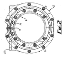
- apparatus for spray coating a pipe particularly a pipe weld joint or field joint, comprises a stator frame 2 and a rotor frame 4.
- the stator frame 2 is intended to be mounted onto a pipe 6 so that it is substantially rotationally fixed relative to the pipe 6.
- the rotor frame 4 is rotationally mounted to a face of the stator frame such that it can rotate relative to the stator frame.
- each section terminate in sliding electrical contacts 18.
- the respective electrical contacts 18 of each section of the frame are arranged to contact each other when the frame 2 is closed so that the conductors 14 form an electrical induction heating coil through which an alternating electrical current can be driven by an external power supply.
- a pneumatic actuator driven locking pin 19 is mounted at the free end of one section of the stator frame 2, operative to fasten the two free ends together when the frame is closed.
- components of a pneumatically driven clamp 19a is mounted on both sections of the stator frame. This feature is only shown (for clarity) in Figure 4 .
- the clamp 19a is provided to aid in closing of the stator frame and, in particular, to help in overcoming frictional resistance between the electrical contacts 18 of each section when they are brought together.
- each pair of guide wheels is rotatably mounted on a shaft 26 which extends from the face plate 8a,10a.
- Two drive motors 28 are also mounted on one of the front face plates (8a).
- the motors are mounted to the rear of the face plate with respective drive shafts extending through the face plate 8a.
- a pair of axially spaced sprockets 30 are mounted on the drive shaft of each motor 28.
- each front and rear face plate 8a,8b,10a,10b of the stator frame there is mounted a pair of rollers 32.
- the surface of the rollers extends beyond the radial inner surface of the face plates and the rollers are mounted for rotation about an axis lying tangentially to the face plate.
- the rollers 32 are arranged to support the frame on a pipe 6 and permit movement of the frame longitudinally relative to the pipe.
- a pair of similar rollers 33 is provided on the end plates 20.
- the rollers 32,33 facilitate movement of the apparatus along a pipe 6.
- the apparatus is substantially fixed relative to the pipe.
- a pair of pneumatically operated claws 33a are mounted on the rear faces 8b,10b respectively of the stator frame 2.
- These clamps comprise radially movable clamp heads 33b operative to bear against the surface of a pipe on which the apparatus is mounted, thereby to secure the apparatus relative to the pipe.
- the rotor frame 4 is comprised of two pairs of arcuate plates 34 with substantially the same length of arc, being about 200 degrees of arc. Each pair comprises an inner plate 34a fastened in spaced-apart relation to an outer plate 34b by a plurality of rods.
- the outer plate 34b of one pair of arcuate plates is mounted between front most inner and outer sets of guide wheels 24.
- the outer edge of the plate has a V-shaped profile which is received into a corresponding circumferential groove on the guide wheels 24.
- the inner plate 34a of the pair has a toothed outer edge which engages with the front most sprocket of each pair of sprockets 30 of the drive motors 28.
- the other pair of arcuate plates is similarly mounted in relation to the rearmost guide wheels and sprockets.
- both pairs of arcuate plates extend over 180 degrees of arc, when they are both mounted on the stator frame there is a degree of overlap of the plates.
- the plates, guide wheels and sprockets are all arranged so that the pairs of plates are interleaved where they overlap. That is to say, where the pair of plates overlap you will find arranged, from the front of the apparatus, an outer plate of the first pair of plates overlying the outer plate from the second pair of plates overlying the inner plate of the first pair overlying the inner plate of the second pair.
- the two pairs of plates are fastened together so that they overlap each other at both ends.
- the pairs of plates are fastened together by a pneumatic actuator operated latch 40, which may comprise a locking pin, mounted towards one end of a pair of arcuate plates and arranged to releasably engage the other pair of plates near a free end of those plates.
- a pneumatic actuator operated latch 40 which may comprise a locking pin, mounted towards one end of a pair of arcuate plates and arranged to releasably engage the other pair of plates near a free end of those plates.
- stator frame 2 may be opened, together with rotor frame 4.
- a pneumatic actuator driven locking clamp 41 is mounted on the front face of each section of the stator frame. These clamps operate to lock the pairs of arcuate plates 34 relative to the stator frame when the frame is opened so that the arcuate plates do not slide out of place.
- the pivot axis of the two sections of the stator frame can be positioned to lie as close to a pipe on which the frame is to be mounted as desired without affecting the spacing of the rotor frame from the pipe.
- a greater spacing of the rotor frame from the pipe is actually desired, for reasons which will become apparent below.
- an applicator 42 for applying a coating to the outside surface of a pipe on which the apparatus is mounted.
- the applicator is mounted to the front most arcuate plate of one of the pairs of arcuate plates via a radial plate 44 and an axial rod assembly 46 extending from the radial plate.
- the applicator 42 is movably mounted on the rod and can be moved along the rod by means of a pneumatic actuator 48. This enables the applicator to be moved longitudinally relative to a pipe on which the apparatus is mounted, and relative to remainder of the apparatus. This enables the applicator to apply a coating to a wider region of the pipe than would otherwise be the case.
- the actuators for driving the locking pin 19, latch 40, clamps 19a, 41 and applicator 42, drive motors 28 and the applicator itself 42 are controlled by a control means 52.
- the control means 52 may be mounted on or separately to the apparatus and also controls the supply of electrical current to the induction heating coil formed by the electrical conductors 14 when the apparatus is closed.
- the control means 52 allows manual control of the apparatus but could also be configured to allow for a degree of automatic control.
- the control means also includes a number of safety interlocks.
- the apparatus is used to apply a coating, typically a liquid or powder coating, to jointed end sections of pipeline where it is necessary to heat the end sections before and/or after the application of the coating.
- a coating typically a liquid or powder coating
- the apparatus In use the apparatus is suspended from a hoist or other suitable lifting apparatus by way of a yoke 54 connected by lines to each section of the stator frame. Lifting the apparatus by the yoke 54 will cause the two sections of the stator frame to separate, opening the frame and allowing the apparatus to be mounted on and removed from a pipe 6.
- the apparatus is lifted by way of the yoke 54, opening the stator 2 and rotor 4 frames (with the separate pairs of arcuate plates of the rotor frame clamped to the stator frame) and then lowered onto a pipeline so that the stator frame and in particular the induction heating coil on the frame, overlies the region of the pipeline to be coated.
- the apparatus is then supported on the pipeline on rollers 33 of the end plates 20 which allow the apparatus to be moved along the length of the pipeline, if required, so that it is a desired position.
- the clamp 19a is operated to draw the pivotally connected parts of the apparatus together, and clamps 33a are engaged secure the first frame relative to the pipeline.
- the clamps 33a are reengaged.
- the two pairs of arcuate plates of the rotor frame are then locked together by operation of the latch 40 and the clamps 41 securing the plates relative to the stator frame 2 are released.
- the applicator 42 is then operated to spray a coating onto the pipeline and the drive motors 28 operated to drive the rotor frame 4 relative to the stator frame 2 and hence move the applicator completely around the pipeline so as to apply coating completely around the circumference of the pipeline.
- the drive motors are reversed.
- the applicator 42 may be moved longitudinally relative to the pipe by moving it along its mounting rod 46.
- the rotor frame is rotated sufficiently and the applicator operated and moved along the mounting rod as desired until the region of the pipe over which the rotor frame is mounted has been adequately coated.
- the motors and various actuators are preferably pneumatically driven. Alternatives, such as electrical or hydraulic, could be employed.
Landscapes
- Coating Apparatus (AREA)
Claims (16)
- Vorrichtung zum Beschichten eines Rohres, wobei die Vorrichtung umfasst:einen ersten Rahmen (2), der angeordnet ist, um an einem Rohr angebracht zu werden;einen zweiten Rahmen (4), der an dem ersten Rahmen (2) drehbar angebracht ist;und eine Beschichtungsauftragseinrichtung (42), die an dem zweiten Rahmen (4) angebracht ist und angeordnet ist, um auf eine Oberfläche des Rohres eine Beschichtung aufzubringen, wenn die Vorrichtung an dem Rohr angebracht ist,dadurch gekennzeichnet, dass:elektrische Leiter (14) an dem ersten Rahmen (2) angebracht sind und angeordnet sind, um eine Induktionsheizspule zu bilden, welche das Rohr umgibt, wenn der erste Rahmen (2) an dem Rohr angebracht ist;der erste und der zweite Rahmen und die Beschichtungsauftragseinrichtung derart angeordnet sind, dass, wenn die Vorrichtung an dem Rohr angebracht ist, die Beschichtungsauftragseinrichtung auf einer Seite der Induktionsheizspule in einer Richtung entlang der Längsachse des Rohres angeordnet ist und in der Lage ist, auf eine Oberfläche des Rohres entlang der Oberfläche des Rohres, welche unter der Induktionsheizspule liegt, eine Beschichtung aufzubringen; unddie Induktionsheizspule näher bei dem Rohr ist als die Beschichtungsauftragseinrichtung.
- Vorrichtung zum Beschichten eines Rohres nach Anspruch 1, wobei der erste Rahmen (2) zwischen einem offenen Zustand, in welchem der erste Rahmen (2) über dem Rohr angeordnet und von diesem entfernt werden kann, und einem geschlossenen Zustand, in welchem der erste Rahmen (2) das Rohr umfassen kann, um dadurch die Vorrichtung an dem Rohr anzubringen, betätigt werden kann, wobei die elektrischen Leiter (14) angeordnet sind, um die Induktionsheizspule zu bilden, wenn sich der erste Rahmen (2) in dem geschlossenen Zustand befindet, wobei der zweite Rahmen (4) mit dem ersten Rahmen (2) zwischen einem offenen Zustand und einem geschlossenen Zustand betätigt werden kann und wobei der erste und der zweite Rahmen und die Beschichtungsauftragseinrichtung (42) derart angeordnet sind, dass, wenn die Vorrichtung an dem Rohr angebracht ist und sich der erste und der zweite Rahmen in dem geschlossenen Zustand befinden, die Beschichtungsauftragseinrichtung (42) auf einer Seite der Induktionsheizspule angeordnet ist und in der Lage ist, auf eine Oberfläche des Rohres entlang der Oberfläche des Rohres, welche unter der Induktionsheizspule liegt, eine Beschichtung aufzubringen.
- Vorrichtung nach Anspruch 1 oder 2, wobei der erste Rahmen (2) mindestens zwei schwenkbar verbundene Abschnitte (8, 10) umfasst.
- Vorrichtung nach Anspruch 3, wenn von Anspruch 2 abhängig, wobei sich die elektrischen Leiter (14) von einem freien Ende eines Abschnitts des ersten Rahmens (2) zu einem freien Ende eines anderen Abschnitts des ersten Rahmens (2) erstrecken, wenn er sich in dem offenen Zustand befindet.
- Vorrichtung nach Anspruch 4, wobei an dem freien Ende jedes Abschnitts die elektrischen Leiter (14) in elektrischen Kontakten (18) enden und die jeweiligen elektrischen Kontakte jedes Abschnitts des ersten Rahmens (2) angeordnet sind, um einander zu berühren, wenn der erste Rahmen (2) geschlossen ist, derart, dass die elektrischen Leiter (14) eine elektrische Induktionsheizspule bilden, durch welche ein Wechselstrom getrieben werden kann.
- Vorrichtung nach einem beliebigen der vorhergehenden Ansprüche, umfassend mindestens eine Rolle (32, 33), die an dem ersten Rahmen (2) angebracht ist, um die Bewegung des ersten Rahmens (2) in Längsrichtung relativ zu dem Rohr zu erleichtern.
- Vorrichtung nach einem beliebigen der vorhergehenden Ansprüche, wobei der erste Rahmen (2) und der zweite Rahmen (4) entlang der Längsachse des Rohres einander benachbart angeordnet sind.
- Vorrichtung nach einem beliebigen der vorhergehenden Ansprüche, wobei der erste Rahmen (2) relativ zu dem Rohr im Wesentlichen drehfest angeordnet werden kann.
- Vorrichtung nach einem beliebigen der vorhergehenden Ansprüche, wobei der erste Rahmen (2) eine Endfläche umfasst und der zweite Rahmen (4) an der Endfläche angebracht ist.
- Vorrichtung nach einem beliebigen der vorhergehenden Ansprüche, wobei der zweite Rahmen (4) aus mindestens zwei getrennten, im Allgemeinen bogenförmigen Gliedern gebildet ist.
- Vorrichtung nach Anspruch 10, wobei die gesamte Bogenlänge der bogenförmigen Glieder größer als 360 Grad ist, so dass sich die bogenförmigen Glieder, die den zweiten Rahmen bilden, überlappen, wenn sie an dem ersten Rahmen (2) angebracht sind.
- Vorrichtung nach einem der vorhergehenden Ansprüche, wobei sich der Radius des ersten Rahmens von dem Radius des zweiten Rahmens unterscheidet.
- Vorrichtung nach einem beliebigen der vorhergehenden Ansprüche, wobei die Beschichtungsauftragseinrichtung (42) angeordnet ist, um eine flüssige oder pulverförmige Beschichtung aufzusprühen.
- Vorrichtung nach einem beliebigen der vorhergehenden Ansprüche, welche einen Schlauchträger umfasst, der dazu dient, einen oder mehrere Schläuche zu tragen, welche verwendet werden, um der Beschichtungsauftragseinrichtung (42) Beschichtungsmaterial zuzuführen.
- Verfahren zum Aufbringen einer Beschichtung auf ein Rohr, umfassend folgende Schritte: Bereitstellen einer Vorrichtung nach einem beliebigen der Ansprüche 1 bis 14; Anbringen der Vorrichtung an dem Rohr, derart, dass die Induktionsheizspule über dem zu beschichtenden Bereich der Rohrleitung liegt; Führen eines Wechselstroms durch die Induktionsheizspule, um den unter der Spule liegenden Bereich der Rohrleitung zu erhitzen; und Bewegen der Vorrichtung in Längsrichtung relativ zu der Rohrleitung, derart, dass die Beschichtungsauftragseinrichtung (42) über dem zu beschichtenden Bereich der Rohrleitung liegt.
- Verfahren nach Anspruch 15, umfassend folgende zusätzliche Schritte: Aufbringen einer Beschichtung wahlweise als Sprühbeschichtung auf den zu beschichtenden Bereich der Rohrleitung; und Drehen des zweiten Rahmens (4) relativ zu dem ersten Rahmen (2), derart, dass sich die Beschichtungsauftragseinrichtung (42) ganz um die Rohrleitung herum bewegt, um um den gesamten Umfang der Rohrleitung herum eine Beschichtung aufzubringen.
Applications Claiming Priority (2)
| Application Number | Priority Date | Filing Date | Title |
|---|---|---|---|
| GBGB0716074.0A GB0716074D0 (en) | 2007-08-17 | 2007-08-17 | Apparatus for coating pipes |
| PCT/GB2008/002757 WO2009024755A1 (en) | 2007-08-17 | 2008-08-15 | Apparatus for coating pipes |
Publications (2)
| Publication Number | Publication Date |
|---|---|
| EP2197592A1 EP2197592A1 (de) | 2010-06-23 |
| EP2197592B1 true EP2197592B1 (de) | 2015-01-07 |
Family
ID=38566557
Family Applications (1)
| Application Number | Title | Priority Date | Filing Date |
|---|---|---|---|
| EP08788326.0A Not-in-force EP2197592B1 (de) | 2007-08-17 | 2008-08-15 | Vorrichtung zur beschichtung von rohren |
Country Status (7)
| Country | Link |
|---|---|
| US (1) | US10486181B2 (de) |
| EP (1) | EP2197592B1 (de) |
| AU (1) | AU2008290350B2 (de) |
| BR (1) | BRPI0815762A2 (de) |
| CA (1) | CA2696695C (de) |
| GB (1) | GB0716074D0 (de) |
| WO (1) | WO2009024755A1 (de) |
Families Citing this family (18)
| Publication number | Priority date | Publication date | Assignee | Title |
|---|---|---|---|---|
| US8800575B2 (en) | 2008-12-30 | 2014-08-12 | Bp Corporation North America Inc. | Apparatus and methods for inspecting and cleaning subsea flex joints |
| US20100178433A1 (en) * | 2009-01-14 | 2010-07-15 | Gm Global Technology Operations, Inc. | Method and apparatus for applying bonding adhesive |
| JP5909823B2 (ja) * | 2012-03-23 | 2016-04-27 | グンゼ株式会社 | 複合部材の製造方法 |
| US9544950B2 (en) | 2013-03-28 | 2017-01-10 | Inductotherm Heating & Welding Ltd | Electric induction heating and coating of the exterior surface of a pipe |
| GB2512644B (en) * | 2013-04-05 | 2016-04-13 | Pipeline Induction Heat Ltd | Applicator machine |
| GB2528469A (en) | 2014-07-22 | 2016-01-27 | Pipeline Induction Heat Ltd | Applicator machine |
| AU2015201875B2 (en) * | 2015-04-14 | 2020-10-01 | Field Joint Coatings Pty Ltd | Pipe spray machine |
| ITUB20152638A1 (it) | 2015-07-30 | 2017-01-30 | Saipem Spa | Apparecchiatura e metodo per rivestire tubazioni |
| CN107088504A (zh) * | 2017-05-17 | 2017-08-25 | 中核核电运行管理有限公司 | 一种管道外壁涂层涂装装置 |
| IT201800007939A1 (it) * | 2018-08-07 | 2020-02-07 | Ibix Srl | Metodo e apparecchiatura per rivestire a fiamma con polveri termoplastiche elementi tubolari |
| US11383259B2 (en) * | 2018-09-07 | 2022-07-12 | Saipem S.P.A. | Machine and method for making a protective joint about an annular junction portion of a pipeline |
| CN110381618B (zh) * | 2019-07-25 | 2021-05-25 | 镇江沅净电子科技有限公司 | 一种电磁感应加热系统及其加热方法 |
| US12042886B2 (en) * | 2020-03-11 | 2024-07-23 | Universal D-Mag Enterprises, Llc | Devices and methods to facilitate welding of pipe sections |
| CN112387540B (zh) * | 2020-11-17 | 2021-12-10 | 四川庆达实业集团有限公司 | 一种热煨弯管3lpe涂覆的控制系统及其控制方法 |
| CN112570185B (zh) * | 2020-12-01 | 2024-12-20 | 聊城职业技术学院 | 树木涂白装置及树木涂白机 |
| CN112695903B (zh) * | 2020-12-23 | 2022-04-22 | 中建筑港集团有限公司 | 一种预留钢筋水泥浆涂刷装置 |
| CN114654715B (zh) * | 2022-02-08 | 2023-10-20 | 河南新开源石化管道有限公司 | 一种弯管防腐胶带缠绕机用中频加热器的整体回转装置 |
| CN114733675B (zh) * | 2022-04-06 | 2024-09-06 | 焦作锦隆彩铝有限公司 | 一种铝型材表面处理设备 |
Family Cites Families (18)
| Publication number | Priority date | Publication date | Assignee | Title |
|---|---|---|---|---|
| US3108022A (en) * | 1960-05-09 | 1963-10-22 | Polymer Processes Inc | Apparatus for coating an elongate body with fluidized coating material |
| NL273178A (de) * | 1961-01-05 | |||
| US4007705A (en) * | 1974-12-20 | 1977-02-15 | Dnd Corporation | Apparatus for treating a cylindrical object |
| US3965551A (en) * | 1975-08-14 | 1976-06-29 | Allied Tube & Conduit Corporation | Production of polymer-coated steel tubing |
| US4237817A (en) | 1979-03-23 | 1980-12-09 | Commercial Resins Company | Apparatus for spraying powder circumferentially around a pipe joint |
| US4388510A (en) * | 1981-06-12 | 1983-06-14 | Commercial Resins Company | Heating collar with quadrafilar windings |
| FR2529215B1 (fr) * | 1982-06-28 | 1987-05-07 | Electricite De France | Procede de preparation de reseaux polymeres de structure interpenetree homogene |
| GB2145639A (en) * | 1983-08-25 | 1985-04-03 | Shaw Ind Ltd | Impact-resistant, moisture-impermeable resinous coatings and method of applying the same to an object |
| US4595607A (en) * | 1985-08-05 | 1986-06-17 | Resource Engineering And Manufacturing Corp. | Combined induction heating and coating system for pipe weld joints |
| GB2228432A (en) | 1989-01-13 | 1990-08-29 | Grayston Central Services | Multi-role machine for heating and coating pipe welds. |
| US5385609A (en) * | 1990-01-26 | 1995-01-31 | E. B. Thomas | Apparatus and method for treating the outer surface of a pipeline |
| US5071672A (en) | 1990-05-29 | 1991-12-10 | Commercial Resins Company | Girth weld heating and coating method |
| US5186755A (en) * | 1990-05-29 | 1993-02-16 | Commercial Resins Company | Girth weld heating and coating system |
| US5178902A (en) * | 1990-12-21 | 1993-01-12 | Shaw Industries Ltd. | High performance composite coating |
| US5417786A (en) * | 1993-04-12 | 1995-05-23 | Denman; George W. | Apparatus and method for coating and wrapping pipe |
| GB2285596B (en) | 1994-01-10 | 1997-09-10 | Heat Pipeline Induction Ltd | An apparatus for coating a pipe weld joint |
| IT1304396B1 (it) * | 1998-11-25 | 2001-03-15 | Socotherm S R L | Metodo per la protezione anticorrosiva in campo dei giunti disaldatura e/o delle zone di rivestimento danneggiate di tubazioni |
| US6911089B2 (en) | 2002-11-01 | 2005-06-28 | Illinois Tool Works Inc. | System and method for coating a work piece |
-
2007
- 2007-08-17 GB GBGB0716074.0A patent/GB0716074D0/en not_active Ceased
-
2008
- 2008-08-15 US US12/673,971 patent/US10486181B2/en not_active Expired - Fee Related
- 2008-08-15 EP EP08788326.0A patent/EP2197592B1/de not_active Not-in-force
- 2008-08-15 BR BRPI0815762 patent/BRPI0815762A2/pt not_active Application Discontinuation
- 2008-08-15 AU AU2008290350A patent/AU2008290350B2/en not_active Ceased
- 2008-08-15 WO PCT/GB2008/002757 patent/WO2009024755A1/en not_active Ceased
- 2008-08-15 CA CA2696695A patent/CA2696695C/en active Active
Also Published As
| Publication number | Publication date |
|---|---|
| EP2197592A1 (de) | 2010-06-23 |
| CA2696695A1 (en) | 2009-02-26 |
| AU2008290350A1 (en) | 2009-02-26 |
| BRPI0815762A2 (pt) | 2015-04-14 |
| US10486181B2 (en) | 2019-11-26 |
| WO2009024755A1 (en) | 2009-02-26 |
| AU2008290350B2 (en) | 2013-01-10 |
| GB0716074D0 (en) | 2007-09-26 |
| US20110159192A1 (en) | 2011-06-30 |
| CA2696695C (en) | 2016-07-12 |
Similar Documents
| Publication | Publication Date | Title |
|---|---|---|
| CA2696695C (en) | Apparatus for coating pipes | |
| US20140076483A1 (en) | Pipe joint coating | |
| US7243697B2 (en) | Apparatus and method for coating pipes | |
| KR20090091259A (ko) | 토치회전형 용접장치 | |
| CN207534136U (zh) | 一种管道焊接装置 | |
| KR102076579B1 (ko) | 파이프용 와이어 권취장치 | |
| AU2020294342B2 (en) | Pipe spray machine | |
| KR101412129B1 (ko) | 배관 내면 코팅장치 | |
| EP3545223B1 (de) | Maschine und verfahren zum reparieren einer rohrleitung in einem gewässer | |
| US20110079310A1 (en) | Mountable traversing carriage | |
| US20220009154A1 (en) | Tape Winding Apparatus and Method | |
| CN117754846B (zh) | 开裂式纤维缠绕机械手与自行走装置、纤维缠绕方法 | |
| US20180186102A1 (en) | A pipe forming assembly and method of use | |
| KR101041583B1 (ko) | 금속 리브관용 패킹부재 보호 필름 설치 장치 | |
| CN222681779U (zh) | 数控弯管热缩防腐机 | |
| CN219704903U (zh) | 管距调节扳手 | |
| KR101723209B1 (ko) | 합성수지관용 와인딩장치 | |
| KR100406229B1 (ko) | 철관 자동 회전장치 | |
| CN120231374B (zh) | 排水管道修复机器人及排水管道修复方法 | |
| CN222950644U (zh) | 长输管线伴热电缆敷设机 | |
| KR100960569B1 (ko) | 강관 외부테이프 코팅장치 및 이를 이용한 강관 코팅 방법 | |
| US20070227647A1 (en) | Apparatus and method for coating pipes | |
| RS51000B (sr) | Mašina za unutrašnje oblaganje cevi malog prečnika namotavanjem na licu mestu | |
| GB2531026A (en) | Apparatus and method for heating a section of a pipeline | |
| CN117644354A (zh) | 一种液压传动的法兰钢管组对定位焊接设备 |
Legal Events
| Date | Code | Title | Description |
|---|---|---|---|
| PUAI | Public reference made under article 153(3) epc to a published international application that has entered the european phase |
Free format text: ORIGINAL CODE: 0009012 |
|
| 17P | Request for examination filed |
Effective date: 20100317 |
|
| AK | Designated contracting states |
Kind code of ref document: A1 Designated state(s): AT BE BG CH CY CZ DE DK EE ES FI FR GB GR HR HU IE IS IT LI LT LU LV MC MT NL NO PL PT RO SE SI SK TR |
|
| AX | Request for extension of the european patent |
Extension state: AL BA MK RS |
|
| DAX | Request for extension of the european patent (deleted) | ||
| 17Q | First examination report despatched |
Effective date: 20110222 |
|
| RIC1 | Information provided on ipc code assigned before grant |
Ipc: B05B 13/04 20060101AFI20131126BHEP Ipc: B05C 9/14 20060101ALI20131126BHEP |
|
| GRAP | Despatch of communication of intention to grant a patent |
Free format text: ORIGINAL CODE: EPIDOSNIGR1 |
|
| INTG | Intention to grant announced |
Effective date: 20140121 |
|
| GRAP | Despatch of communication of intention to grant a patent |
Free format text: ORIGINAL CODE: EPIDOSNIGR1 |
|
| INTG | Intention to grant announced |
Effective date: 20140527 |
|
| GRAS | Grant fee paid |
Free format text: ORIGINAL CODE: EPIDOSNIGR3 |
|
| GRAA | (expected) grant |
Free format text: ORIGINAL CODE: 0009210 |
|
| AK | Designated contracting states |
Kind code of ref document: B1 Designated state(s): AT BE BG CH CY CZ DE DK EE ES FI FR GB GR HR HU IE IS IT LI LT LU LV MC MT NL NO PL PT RO SE SI SK TR |
|
| REG | Reference to a national code |
Ref country code: GB Ref legal event code: FG4D |
|
| REG | Reference to a national code |
Ref country code: CH Ref legal event code: EP |
|
| REG | Reference to a national code |
Ref country code: IE Ref legal event code: FG4D |
|
| REG | Reference to a national code |
Ref country code: NL Ref legal event code: T3 |
|
| REG | Reference to a national code |
Ref country code: AT Ref legal event code: REF Ref document number: 705323 Country of ref document: AT Kind code of ref document: T Effective date: 20150215 |
|
| REG | Reference to a national code |
Ref country code: DE Ref legal event code: R096 Ref document number: 602008036251 Country of ref document: DE Effective date: 20150226 |
|
| REG | Reference to a national code |
Ref country code: NO Ref legal event code: T2 Effective date: 20150107 |
|
| REG | Reference to a national code |
Ref country code: AT Ref legal event code: MK05 Ref document number: 705323 Country of ref document: AT Kind code of ref document: T Effective date: 20150107 |
|
| REG | Reference to a national code |
Ref country code: LT Ref legal event code: MG4D |
|
| PG25 | Lapsed in a contracting state [announced via postgrant information from national office to epo] |
Ref country code: ES Free format text: LAPSE BECAUSE OF FAILURE TO SUBMIT A TRANSLATION OF THE DESCRIPTION OR TO PAY THE FEE WITHIN THE PRESCRIBED TIME-LIMIT Effective date: 20150107 Ref country code: FI Free format text: LAPSE BECAUSE OF FAILURE TO SUBMIT A TRANSLATION OF THE DESCRIPTION OR TO PAY THE FEE WITHIN THE PRESCRIBED TIME-LIMIT Effective date: 20150107 Ref country code: HR Free format text: LAPSE BECAUSE OF FAILURE TO SUBMIT A TRANSLATION OF THE DESCRIPTION OR TO PAY THE FEE WITHIN THE PRESCRIBED TIME-LIMIT Effective date: 20150107 Ref country code: SE Free format text: LAPSE BECAUSE OF FAILURE TO SUBMIT A TRANSLATION OF THE DESCRIPTION OR TO PAY THE FEE WITHIN THE PRESCRIBED TIME-LIMIT Effective date: 20150107 Ref country code: LT Free format text: LAPSE BECAUSE OF FAILURE TO SUBMIT A TRANSLATION OF THE DESCRIPTION OR TO PAY THE FEE WITHIN THE PRESCRIBED TIME-LIMIT Effective date: 20150107 Ref country code: BG Free format text: LAPSE BECAUSE OF FAILURE TO SUBMIT A TRANSLATION OF THE DESCRIPTION OR TO PAY THE FEE WITHIN THE PRESCRIBED TIME-LIMIT Effective date: 20150407 |
|
| PG25 | Lapsed in a contracting state [announced via postgrant information from national office to epo] |
Ref country code: GR Free format text: LAPSE BECAUSE OF FAILURE TO SUBMIT A TRANSLATION OF THE DESCRIPTION OR TO PAY THE FEE WITHIN THE PRESCRIBED TIME-LIMIT Effective date: 20150408 Ref country code: PL Free format text: LAPSE BECAUSE OF FAILURE TO SUBMIT A TRANSLATION OF THE DESCRIPTION OR TO PAY THE FEE WITHIN THE PRESCRIBED TIME-LIMIT Effective date: 20150107 Ref country code: AT Free format text: LAPSE BECAUSE OF FAILURE TO SUBMIT A TRANSLATION OF THE DESCRIPTION OR TO PAY THE FEE WITHIN THE PRESCRIBED TIME-LIMIT Effective date: 20150107 Ref country code: IS Free format text: LAPSE BECAUSE OF FAILURE TO SUBMIT A TRANSLATION OF THE DESCRIPTION OR TO PAY THE FEE WITHIN THE PRESCRIBED TIME-LIMIT Effective date: 20150507 Ref country code: LV Free format text: LAPSE BECAUSE OF FAILURE TO SUBMIT A TRANSLATION OF THE DESCRIPTION OR TO PAY THE FEE WITHIN THE PRESCRIBED TIME-LIMIT Effective date: 20150107 |
|
| REG | Reference to a national code |
Ref country code: DE Ref legal event code: R097 Ref document number: 602008036251 Country of ref document: DE |
|
| PG25 | Lapsed in a contracting state [announced via postgrant information from national office to epo] |
Ref country code: EE Free format text: LAPSE BECAUSE OF FAILURE TO SUBMIT A TRANSLATION OF THE DESCRIPTION OR TO PAY THE FEE WITHIN THE PRESCRIBED TIME-LIMIT Effective date: 20150107 Ref country code: DK Free format text: LAPSE BECAUSE OF FAILURE TO SUBMIT A TRANSLATION OF THE DESCRIPTION OR TO PAY THE FEE WITHIN THE PRESCRIBED TIME-LIMIT Effective date: 20150107 Ref country code: RO Free format text: LAPSE BECAUSE OF FAILURE TO SUBMIT A TRANSLATION OF THE DESCRIPTION OR TO PAY THE FEE WITHIN THE PRESCRIBED TIME-LIMIT Effective date: 20150107 Ref country code: SK Free format text: LAPSE BECAUSE OF FAILURE TO SUBMIT A TRANSLATION OF THE DESCRIPTION OR TO PAY THE FEE WITHIN THE PRESCRIBED TIME-LIMIT Effective date: 20150107 Ref country code: CZ Free format text: LAPSE BECAUSE OF FAILURE TO SUBMIT A TRANSLATION OF THE DESCRIPTION OR TO PAY THE FEE WITHIN THE PRESCRIBED TIME-LIMIT Effective date: 20150107 |
|
| PLBE | No opposition filed within time limit |
Free format text: ORIGINAL CODE: 0009261 |
|
| STAA | Information on the status of an ep patent application or granted ep patent |
Free format text: STATUS: NO OPPOSITION FILED WITHIN TIME LIMIT |
|
| 26N | No opposition filed |
Effective date: 20151008 |
|
| PG25 | Lapsed in a contracting state [announced via postgrant information from national office to epo] |
Ref country code: SI Free format text: LAPSE BECAUSE OF FAILURE TO SUBMIT A TRANSLATION OF THE DESCRIPTION OR TO PAY THE FEE WITHIN THE PRESCRIBED TIME-LIMIT Effective date: 20150107 |
|
| PG25 | Lapsed in a contracting state [announced via postgrant information from national office to epo] |
Ref country code: LU Free format text: LAPSE BECAUSE OF FAILURE TO SUBMIT A TRANSLATION OF THE DESCRIPTION OR TO PAY THE FEE WITHIN THE PRESCRIBED TIME-LIMIT Effective date: 20150815 Ref country code: MC Free format text: LAPSE BECAUSE OF FAILURE TO SUBMIT A TRANSLATION OF THE DESCRIPTION OR TO PAY THE FEE WITHIN THE PRESCRIBED TIME-LIMIT Effective date: 20150107 |
|
| REG | Reference to a national code |
Ref country code: CH Ref legal event code: PL |
|
| PG25 | Lapsed in a contracting state [announced via postgrant information from national office to epo] |
Ref country code: CH Free format text: LAPSE BECAUSE OF NON-PAYMENT OF DUE FEES Effective date: 20150831 Ref country code: LI Free format text: LAPSE BECAUSE OF NON-PAYMENT OF DUE FEES Effective date: 20150831 |
|
| PG25 | Lapsed in a contracting state [announced via postgrant information from national office to epo] |
Ref country code: BE Free format text: LAPSE BECAUSE OF FAILURE TO SUBMIT A TRANSLATION OF THE DESCRIPTION OR TO PAY THE FEE WITHIN THE PRESCRIBED TIME-LIMIT Effective date: 20150107 |
|
| REG | Reference to a national code |
Ref country code: IE Ref legal event code: MM4A |
|
| REG | Reference to a national code |
Ref country code: FR Ref legal event code: PLFP Year of fee payment: 9 |
|
| PG25 | Lapsed in a contracting state [announced via postgrant information from national office to epo] |
Ref country code: IE Free format text: LAPSE BECAUSE OF NON-PAYMENT OF DUE FEES Effective date: 20150815 |
|
| PG25 | Lapsed in a contracting state [announced via postgrant information from national office to epo] |
Ref country code: MT Free format text: LAPSE BECAUSE OF FAILURE TO SUBMIT A TRANSLATION OF THE DESCRIPTION OR TO PAY THE FEE WITHIN THE PRESCRIBED TIME-LIMIT Effective date: 20150107 |
|
| PG25 | Lapsed in a contracting state [announced via postgrant information from national office to epo] |
Ref country code: HU Free format text: LAPSE BECAUSE OF FAILURE TO SUBMIT A TRANSLATION OF THE DESCRIPTION OR TO PAY THE FEE WITHIN THE PRESCRIBED TIME-LIMIT; INVALID AB INITIO Effective date: 20080815 |
|
| PG25 | Lapsed in a contracting state [announced via postgrant information from national office to epo] |
Ref country code: CY Free format text: LAPSE BECAUSE OF FAILURE TO SUBMIT A TRANSLATION OF THE DESCRIPTION OR TO PAY THE FEE WITHIN THE PRESCRIBED TIME-LIMIT Effective date: 20150107 |
|
| REG | Reference to a national code |
Ref country code: FR Ref legal event code: PLFP Year of fee payment: 10 |
|
| PG25 | Lapsed in a contracting state [announced via postgrant information from national office to epo] |
Ref country code: TR Free format text: LAPSE BECAUSE OF FAILURE TO SUBMIT A TRANSLATION OF THE DESCRIPTION OR TO PAY THE FEE WITHIN THE PRESCRIBED TIME-LIMIT Effective date: 20150107 |
|
| PG25 | Lapsed in a contracting state [announced via postgrant information from national office to epo] |
Ref country code: PT Free format text: LAPSE BECAUSE OF FAILURE TO SUBMIT A TRANSLATION OF THE DESCRIPTION OR TO PAY THE FEE WITHIN THE PRESCRIBED TIME-LIMIT Effective date: 20150107 |
|
| REG | Reference to a national code |
Ref country code: FR Ref legal event code: PLFP Year of fee payment: 11 |
|
| PGFP | Annual fee paid to national office [announced via postgrant information from national office to epo] |
Ref country code: FR Payment date: 20200715 Year of fee payment: 13 Ref country code: DE Payment date: 20200804 Year of fee payment: 13 |
|
| REG | Reference to a national code |
Ref country code: DE Ref legal event code: R119 Ref document number: 602008036251 Country of ref document: DE |
|
| PG25 | Lapsed in a contracting state [announced via postgrant information from national office to epo] |
Ref country code: FR Free format text: LAPSE BECAUSE OF NON-PAYMENT OF DUE FEES Effective date: 20210831 Ref country code: DE Free format text: LAPSE BECAUSE OF NON-PAYMENT OF DUE FEES Effective date: 20220301 |
|
| PGFP | Annual fee paid to national office [announced via postgrant information from national office to epo] |
Ref country code: NL Payment date: 20220615 Year of fee payment: 15 Ref country code: GB Payment date: 20220623 Year of fee payment: 15 |
|
| PGFP | Annual fee paid to national office [announced via postgrant information from national office to epo] |
Ref country code: NO Payment date: 20220809 Year of fee payment: 15 Ref country code: IT Payment date: 20220712 Year of fee payment: 15 |
|
| REG | Reference to a national code |
Ref country code: NL Ref legal event code: MM Effective date: 20230901 |
|
| GBPC | Gb: european patent ceased through non-payment of renewal fee |
Effective date: 20230815 |
|
| PG25 | Lapsed in a contracting state [announced via postgrant information from national office to epo] |
Ref country code: NL Free format text: LAPSE BECAUSE OF NON-PAYMENT OF DUE FEES Effective date: 20230901 |
|
| PG25 | Lapsed in a contracting state [announced via postgrant information from national office to epo] |
Ref country code: NO Free format text: LAPSE BECAUSE OF NON-PAYMENT OF DUE FEES Effective date: 20230831 Ref country code: NL Free format text: LAPSE BECAUSE OF NON-PAYMENT OF DUE FEES Effective date: 20230901 |
|
| PG25 | Lapsed in a contracting state [announced via postgrant information from national office to epo] |
Ref country code: GB Free format text: LAPSE BECAUSE OF NON-PAYMENT OF DUE FEES Effective date: 20230815 |
|
| PG25 | Lapsed in a contracting state [announced via postgrant information from national office to epo] |
Ref country code: IT Free format text: LAPSE BECAUSE OF NON-PAYMENT OF DUE FEES Effective date: 20230815 Ref country code: GB Free format text: LAPSE BECAUSE OF NON-PAYMENT OF DUE FEES Effective date: 20230815 |