EP2197663B1 - Onduleuse - Google Patents
Onduleuse Download PDFInfo
- Publication number
- EP2197663B1 EP2197663B1 EP08776142.5A EP08776142A EP2197663B1 EP 2197663 B1 EP2197663 B1 EP 2197663B1 EP 08776142 A EP08776142 A EP 08776142A EP 2197663 B1 EP2197663 B1 EP 2197663B1
- Authority
- EP
- European Patent Office
- Prior art keywords
- adhesive
- corrugations
- corrugator
- cylinder
- corrugation
- Prior art date
- Legal status (The legal status is an assumption and is not a legal conclusion. Google has not performed a legal analysis and makes no representation as to the accuracy of the status listed.)
- Not-in-force
Links
- 239000000853 adhesive Substances 0.000 claims description 95
- 230000001070 adhesive effect Effects 0.000 claims description 95
- 239000000463 material Substances 0.000 claims description 83
- 230000001154 acute effect Effects 0.000 claims description 5
- 239000007767 bonding agent Substances 0.000 claims description 5
- 241000826860 Trapezium Species 0.000 claims description 2
- 230000007246 mechanism Effects 0.000 claims description 2
- 238000000034 method Methods 0.000 description 16
- 230000008569 process Effects 0.000 description 13
- 238000003825 pressing Methods 0.000 description 7
- 230000009467 reduction Effects 0.000 description 6
- 230000008901 benefit Effects 0.000 description 3
- 239000003292 glue Substances 0.000 description 3
- 239000010410 layer Substances 0.000 description 3
- 229920002472 Starch Polymers 0.000 description 2
- 230000000694 effects Effects 0.000 description 2
- 230000007613 environmental effect Effects 0.000 description 2
- 239000000835 fiber Substances 0.000 description 2
- 230000005484 gravity Effects 0.000 description 2
- 238000010438 heat treatment Methods 0.000 description 2
- 230000014759 maintenance of location Effects 0.000 description 2
- 239000000123 paper Substances 0.000 description 2
- 230000000717 retained effect Effects 0.000 description 2
- 235000019698 starch Nutrition 0.000 description 2
- 239000008107 starch Substances 0.000 description 2
- 239000004593 Epoxy Substances 0.000 description 1
- NIXOWILDQLNWCW-UHFFFAOYSA-N acrylic acid group Chemical group C(C=C)(=O)O NIXOWILDQLNWCW-UHFFFAOYSA-N 0.000 description 1
- 238000004026 adhesive bonding Methods 0.000 description 1
- 239000002131 composite material Substances 0.000 description 1
- 230000006835 compression Effects 0.000 description 1
- 238000007906 compression Methods 0.000 description 1
- 230000003247 decreasing effect Effects 0.000 description 1
- 238000001035 drying Methods 0.000 description 1
- 238000005265 energy consumption Methods 0.000 description 1
- 239000005038 ethylene vinyl acetate Substances 0.000 description 1
- 239000002657 fibrous material Substances 0.000 description 1
- -1 for example Substances 0.000 description 1
- 231100001261 hazardous Toxicity 0.000 description 1
- 239000007769 metal material Substances 0.000 description 1
- 230000004048 modification Effects 0.000 description 1
- 238000012986 modification Methods 0.000 description 1
- 229920002689 polyvinyl acetate Polymers 0.000 description 1
- 239000011118 polyvinyl acetate Substances 0.000 description 1
- 230000003252 repetitive effect Effects 0.000 description 1
- 229920005989 resin Polymers 0.000 description 1
- 239000011347 resin Substances 0.000 description 1
- 239000002356 single layer Substances 0.000 description 1
- 230000032258 transport Effects 0.000 description 1
Images

Classifications
-
- B—PERFORMING OPERATIONS; TRANSPORTING
- B31—MAKING ARTICLES OF PAPER, CARDBOARD OR MATERIAL WORKED IN A MANNER ANALOGOUS TO PAPER; WORKING PAPER, CARDBOARD OR MATERIAL WORKED IN A MANNER ANALOGOUS TO PAPER
- B31F—MECHANICAL WORKING OR DEFORMATION OF PAPER, CARDBOARD OR MATERIAL WORKED IN A MANNER ANALOGOUS TO PAPER
- B31F1/00—Mechanical deformation without removing material, e.g. in combination with laminating
- B31F1/20—Corrugating; Corrugating combined with laminating to other layers
- B31F1/24—Making webs in which the channel of each corrugation is transverse to the web feed
- B31F1/30—Tools secured to endless chains, e.g. toothed belts; combined with uniting the corrugated web to flat webs
-
- B—PERFORMING OPERATIONS; TRANSPORTING
- B31—MAKING ARTICLES OF PAPER, CARDBOARD OR MATERIAL WORKED IN A MANNER ANALOGOUS TO PAPER; WORKING PAPER, CARDBOARD OR MATERIAL WORKED IN A MANNER ANALOGOUS TO PAPER
- B31F—MECHANICAL WORKING OR DEFORMATION OF PAPER, CARDBOARD OR MATERIAL WORKED IN A MANNER ANALOGOUS TO PAPER
- B31F1/00—Mechanical deformation without removing material, e.g. in combination with laminating
- B31F1/20—Corrugating; Corrugating combined with laminating to other layers
- B31F1/24—Making webs in which the channel of each corrugation is transverse to the web feed
- B31F1/26—Making webs in which the channel of each corrugation is transverse to the web feed by interengaging toothed cylinders cylinder constructions
- B31F1/28—Making webs in which the channel of each corrugation is transverse to the web feed by interengaging toothed cylinders cylinder constructions combined with uniting the corrugated webs to flat webs ; Making double-faced corrugated cardboard
- B31F1/2818—Glue application specially adapted therefor
-
- Y—GENERAL TAGGING OF NEW TECHNOLOGICAL DEVELOPMENTS; GENERAL TAGGING OF CROSS-SECTIONAL TECHNOLOGIES SPANNING OVER SEVERAL SECTIONS OF THE IPC; TECHNICAL SUBJECTS COVERED BY FORMER USPC CROSS-REFERENCE ART COLLECTIONS [XRACs] AND DIGESTS
- Y10—TECHNICAL SUBJECTS COVERED BY FORMER USPC
- Y10T—TECHNICAL SUBJECTS COVERED BY FORMER US CLASSIFICATION
- Y10T428/00—Stock material or miscellaneous articles
- Y10T428/24—Structurally defined web or sheet [e.g., overall dimension, etc.]
- Y10T428/24628—Nonplanar uniform thickness material
- Y10T428/24661—Forming, or cooperating to form cells
Definitions
- This invention relates to a corrugating machine also known as a corrugator.
- Known corrugating machines for forming corrugated board have intermeshing rollers.
- the outer surfaces of the rollers are integrally formed with elongate grooves and ridges which extend the length of the roller in parallel with its rotational axis. Since the rollers are positioned so that the grooves of one roller can intermesh with the ridges of the other roller, when a sheet of flexible material, such as paper or card, is fed therebetween, transversely extending corrugations, also known as flutes, are formed along its length.
- the pressing process used in known conventional corrugating machines cannot be used with certain types of flexible material, for example, paper with a long fibre length. Such materials may have a greater strength than that of the materials currently used within the corrugation process and as such the strength of the corrugated material is limited by said pressing process.
- a corrugating machine with a curved base element and a flat base element in accordance with the preamble of claim 1 is known from US-A-1 802 880 .
- Conventional corrugating machines construct corrugated board by gluing liners to the ridges of both sides of the corrugated material. Hot starch glue is applied along the entire length of each ridge, the liners then being pressed onto the corrugated material under heating so as to cure the glue. As before, the use of heat results in an expensive process with a high-energy requirement. Also, applying glue along the entire length of each ridge is both environmentally and financially wasteful.
- the continuously curving surface of the corrugations in said flexible material, which forms part of the corrugated board, has two main limitations due to its wave-like or sinusoidal profile:
- the present invention seeks to overcome these problems.
- a corrugator comprising:
- interdigitating is defined as where two components (in this case the corresponding corrugation formers of the curved and flat base element) interweave or interlock in a repetitive alternating adjacent manner, similar in nature to that which occurs when one crosses one's fingers.
- said curved base element is generally cylindrical. This results in the base element having a constant radius as it is rotated and as such the flat base element can be located at a constant distance from said rotation axis as it translates and hence reduces the complexity of movement of the corrugator.
- said flat base element comprises a plurality of similar flat members joined to one another in an end to end manner by at least one linkage such that the flat portions form a continuous conveyor. This enables the corrugation process to be continuous.
- said corrugating formers are operable at room temperature to form corrugations in the flexible material. This will result in reduced operating costs compared to a higher temperature process.
- the corrugating formers are positioned and shaped such that the profile of the corrugations created in said flexible material comprises at least two straight sides.
- the straight sides result in an increase in crush strength of corrugated board formed from the corrugated material.
- the corrugating formers are positioned and shaped such that the profile of the corrugations created in said flexible material is substantially an isosceles triangle with its base removed comprising folded or creased radiused apex portion intermediate two straight or flat side portions at an acute angle to one another.
- said acute angle is in the range of 60 to 64 degrees.
- the range is 60 to 61.5 degrees.
- the angle is 61.1 degrees.
- Such an angle, or range of angles not only increases the crush strength of corrugated board formed from the corrugated material, but also increases the strength of such a board by enabling a greater concentration or number of corrugations in said flexible material per unit distance, generally increasing the number of corrugations by 25% per unit linear distance, allowing each base element to have at least five corrugation formers per linear inch (25.4 millimetres).
- the corrugator additionally comprises liner means for affixing a liner to each of the corrugations on a first side of said flexible material following corrugation. This enables the creation of single face corrugated board.
- the liner means includes a room temperature bonding agent.
- a bonding agent is relatively easy and cheap to cure.
- Adhesive is fed to said adhesive cylinder such that the adhesive cylinder applies a portion of adhesive to a plurality of discrete portions of each corrugation on said first side of said corrugated material. This leads to a reduction in the volume of adhesive used per corrugating and hence a reduction in cost. It also reduces warping of both the corrugated and liner material.
- the in use metering blade applies a constant or substantially constant volume of adhesive to said adhesive cylinder in any given time period.
- the pitch of a plurality of channels determines the volume of adhesive which is transferred from said adhesive cylinder to said portion of each of the corrugations.
- replacing said metering blade allows the pitch of said plurality of channels to be changed.
- the lateral dimension of the at least one channel is devised so as to apply a particular discrete volume of adhesive to each corrugation.
- said metering blade comprises an edge which removes excess adhesive from the adhesive cylinder. This reduces wastage of adhesive.
- the corrugator additionally comprises liner means for affixing a liner to each of the corrugations on a first side of said flexible material following corrugation. This enables the creation of single face corrugated board.
- the liner means includes a room temperature bonding agent.
- a bonding agent is relatively easy and cheap to cure.
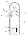
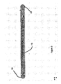
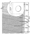
- the corrugator As seen best in Figure 1 , the corrugator, indicated generally as 10, comprises a generally flat base element 12 and a generally cylindrical base element 14 adjacent the flat base element 12.
- the flat base element 12 comprises a plurality of similar generally flat base members or plates 16 which are linked together so as to form a continuous conveyor 18 which pivots around end sprockets 20, 22.
- the sprockets 20, 22 may be provided with teeth 23 which are received within corresponding recesses (not shown) on the underside of each base plate 16.
- the cylindrical base element 14 is rotatably held in a fixed position relative to the conveyor 18, for example by a fixed support element (not shown).
- Both of the base elements 12, 14 have a plurality of corresponding generally v-shaped lateral cross-section corrugation formers 24 which extend parallel to the axis of rotation of the cylindrical base element 14.
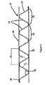
- the formers 24 are sized and positioned such that, as best seen in Figure 4 , as the base element 14 is rotated the corresponding formers 24 on each base element 12, 14 interdigitate, with the peak 13 of the former 24 of one base element 14 being received within a trough 15 of the corresponding former of the other base element 12 and vice-versa, hence driving the flat base element 12 (and consequently the conveyor 18) in a linear manner at a tangent to the rotational motion of the curved base element 14.
- the conveyor 18 is rotated such that the flat base element 12 moves in a linear manner, this will drive the rotation of the curved base element 14.
- the driving of the conveyor 18 may be effected by a motor (not shown) mechanically linked to one of the end sprockets 20, 22.
- the corresponding formers 24 serve to both fold the flexible material 26 so as to create creased corrugations at a non-elevated or room temperature and, as the base element 14 rotates, feed the material 26 between said formers 24 such that a plurality of identical corrugations 25 are formed adjacent one another along the length of the material 26 in a direction parallel to the direction of motion of the base element 12.
- the folding occurs predominately between the peaks 13 of corresponding adjacent formers 24: one of which is of the first base element 12 and the other of which is of the second base element 14.
- Each creased corrugation extends across the width of the material 26 in a direction parallel to that of the axis of rotation of the base element 14.
- the process used by the corrugator 10 to create the corrugations 25 differs from that of conventional corrugators in that the corrugations 25 are formed in the material 26 by a plurality of discrete folds, as opposed to being pressed into the material in a hot atmosphere of steam at high pressure.
- Conventional corrugation forming using steam and elevated temperatures actually reconfigures the fibres of the material being corrugated, resulting in the material remaining continuously curved once cooled.
- cold pressing to form corrugations by discrete folds reduces the complexity of the corrugator and lessens both the financial and environmental cost of the process.
- the lateral cross-section of the formers 24 is chosen so as to create corrugations of a particular profile.
- An example of the profile of corrugation 25 produced by the corrugator 10 is shown in Figure 5 .
- the folding technique creates creased corrugations 25 with straight sides 34.
- Corrugations created by the conventional pressing technique have curved sides and are not creased or folded, such that the profile is continuously arcuate and substantially sinusoidal.
- a corrugated board 32 is manufactured by sandwiching the corrugated material 26 between two liner layers 28, 30.
- Corrugated board 32 which comprises sinusoidal corrugation corrugated material, such as that manufactured using the pressing method mentioned above, has less compressive or 'crush' strength in the direction parallel to the height of the corrugations 25 compared to that which comprises corrugations 25 with straight sides 34.
- the corrugations 25 have a radiused apex portion 36 intermediate each straight or flat side 34.
- Using a different lateral cross-section of corrugation former 24 it is also possible to create corrugations 25 with a profile which comprises a straight portion (not shown) intermediate each straight side 34 instead of the radiused apex portion 36. This has the advantage that each corrugation 25 has a greater surface area which may provide a larger bonding surface for said liner layers 28, 30 and hence a stronger bond.
- corrugations created in this manner can have sides 34 which subtend a much smaller angle 38 compared to those formed by the pressing method. In the case of Figure 5 , this angle is 61.1 degrees.
- the corrugator 10 may produce corrugations 25 with an angle 38 in the range of 60 to 64 degrees by using corrugation formers 24 of a different size and shape. The use of corrugations 25 with an angle in this range results in corrugated board with a greater crush strength compared to conventionally pressed corrugated board.
- corrugations 25 per unit length of board, preferably at least 5 corrugations per inch (25.4 mm) which heretofore has not been possible, and the flat sides 34 of the corrugations 25 being such that they lie in a direction, a greater component of which is perpendicular to the planes of the liner layers 28, 30.
- the at least 5 corrugations per inch (25.4mm) are created in 3mm thick B-flute calliper type board.
- corrugated board 32 By decreasing the pitch of the corrugations 25 per unit length of corrugated material 26 results in corrugated board 32 having greater compressive strength in a direction of the longitudinal extent of each corrugation 25. In other words, the 'spine strength' of the corrugations, and thus also the corrugated material, is increased.
- Such means may comprise a plurality of apertures (not shown) in a surface of each base plate 16, which are linked by an airtight conduit (also not shown) to a vacuum pump.
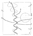
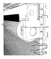
- the conveyor 18 carries the corrugated material 26 to an adhesive apparatus (indicated generally as 40).
- the adhesive apparatus 40 comprises an adhesive tank 41 which contains the adhesive to be used.
- the apparatus also comprises a rotatable cylinder 42.
- the cylinder 42 is positioned and sized such that its axis of rotation is parallel to that of the base element 14 and such that it is adjacent to the conveyor 18, the conveyor 18 forming a tangential surface relative to the circumferential surface of the cylinder 42.
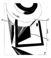
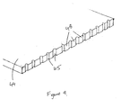
- a metering blade 44 which runs parallel to the axis of rotation of the cylinder 42 and extends along the cylinder's entire length, is positioned such that it abuts the circumferential surface of the cylinder 42.
- the channels 45 run in a direction perpendicular to the axis of rotation of the cylinder 42 and act such that as the cylinder 42 is rotated in the direction indicated by arrow 46, adhesive 48 is drawn through the plurality of openings provided between the channels 45 and the circumferential surface of the cylinder 42.
- the cylinder 42 rotates such that its circumferential surface travels at a speed similar or identical to the speed of the conveyor 18.
- the ring-like adhesive portions 48 protrude from the surface of the cylinder 42 such that as the corrugated material 26 passes the cylinder 42 on the conveyor 18, the radiused apex portions 36 of the of the ridges of the corrugations 25 closest the cylinder surface contact the adhesive 48 and as such a quantity of adhesive is transferred to the material. Due to a combination of the spacing of the ring-like adhesive portions 48 and the spacing of the corrugations 25, a plurality of row and columns of discrete spots 50 of adhesive are applied to the material 26 by the cylinder 42. The cylinder 42 continues rotating, replenishing the adhesive at the metering blade 44 and continuously applying it to the corrugated material 26 as described.
- Conventional corrugators use a starch-based adhesive which is applied at high temperatures (in excess of 100 degrees Celsius) along the entire length of each corrugation 25.
- the proposed invention uses an adhesive which is applied at room temperature, typically in the range of 19 to 25 degrees Celsius, to discrete portions along the length of each corrugation 25.
- the combination of energy saved by not heating the adhesive and adhesive saved due to using discrete portions leads to a saving in both financial and environmental cost by the present invention.
- Such an adhesive that can be used is polyvinyl acetate (also known as PVA) adhesive. It has been found that such an adhesive has a 4 second fibre tack time at room temperature.
- PVA polyvinyl acetate
- a further advantage of the present invention is that conventional corrugators require a long conveyor to allow drying of the adhesive and as the corrugated board formed by the corrugator of the present invention does not require high temperatures to dry the adhesive, the conveyor 18 and hence the total size of the corrugator 10 can be more compact.
- the conveyor 18 transports the corrugated material 26 to liner apparatus (not shown), which applies a sheet of liner material to the radiused apex portions of the corrugated material 26 having adhesive thereon.
- liner apparatus not shown
- this process has always been carried out whereby the corrugated material and applied adhesive are retained on a first rotating curved surface, such as a drum, with the liner being fed to and applied to the corrugations at a tangent to the first curved surface by a second rotating curved surface, such as a roller, adjacent the first rotating curved surface.
- the corrugated material 26 and applied adhesive 50 is retained on a linear surface, which may be part of the conveyor 18 or part of another linear conveyor (not shown), and the liner is linearly fed by linear feeding means to the corrugations at an angle to the linear surface.
- the retention surface of the present invention does not rotate and can be orientated such that gravity acts to maintain the adhesive on the corrugated material, loss of adhesive from the corrugated material is much less likely to occur.
- the adhesive application and liner process may then be repeated following the affixing of the first liner sheet so as to apply a second liner sheet to the other side of the corrugated material.
- the flexible material could be a plast.ics material, a metal material, a composite material, or any other suitable flexible material.
- the flexible material used either to form corrugations or as a liner, is typically a sheet, one or more strips could be corrugated or applied as a liner.
- the flexible material may by a single layer, or multiple layers.
- the corrugation formers could be shaped so as to produce substantially isosceles trapezium shaped corrugations comprising a substantially flat plateau portion intermediate two straight or flat side portions at an acute angle to one another. This would enable the intermediate plateau portion to provide a large surface area for a liner to be attached.
- the rotatable base element could be in the form of a conveyor, instead of a roller.
- the conveyor functions by the co-operation of chain and sprockets.
- alternate drive methods are envisaged such as belt and pulleys.
- EVA Ethylene Vinyl Acetate
- epoxy epoxy or acrylic based resins
- the adhesive tank and adhesive metering means could be provided within the adhesive cylinder to feed adhesive to the exterior surface of the cylinder via, for example a plurality of groups of small apertures arranged in discrete rings around the cylinder.
- corrugations As a series of discrete folds, compared with pressing the corrugations at high temperatures, effects not only a greater concentration in corrugations per unit distance but also a reduction in financial costs and energy consumption.
- the greater concentration of corrugations gives rise to not only an increase in compressive strength in a direction parallel to the height of the corrugations, but also in an increase in compressive strength of the longitudinal extent of each corrugation.
- the use of discrete folds enables the creation of corrugations with a non-arcuate cross-section with radiused apex regions.
- the non-arcuate shape leads to an increase in compressive strength in a direction parallel to the height of the corrugations; and the radiused apex region allows greater bonding strength between each corrugation and an attached liner sheet.
- the non-arcuate shape incorporates flat regions which lie in a plane, a component of which is perpendicular to the plane of attached liners. This also effects an increase in compressive strength of corrugated board in a direction parallel to the height of the corrugations.
Landscapes
- Engineering & Computer Science (AREA)
- Mechanical Engineering (AREA)
- Laminated Bodies (AREA)
- Machines For Manufacturing Corrugated Board In Mechanical Paper-Making Processes (AREA)
- Shaping Of Tube Ends By Bending Or Straightening (AREA)
Claims (11)
- Onduleuse comprenant :un élément de base incurvé (14) apte à tourner autour d'un axe de rotation,un élément de base plat (12) apte à se déplacer en translation par rapport audit axe de rotation,lesdits éléments de base (12, 14) ayant une pluralité d'organes de formation d'ondulation correspondants (24) de telle sorte qu'un matériau souple (26) peut être alimenté entre lesdits éléments de base (12, 14), les organes de formation d'ondulation correspondants (24) s'interdigitant de telle sorte que ledit matériau souple (26) est plié à une température non élevée par la coopération des organes de formation d'ondulation (24) de façon à créer des ondulations plissées (25) dans le matériau souple (26) ;caractérisé par un moyen de vide pour retenir ledit matériau souple (26) sur les organes de formation d'ondulation (24) de l'élément de base plat (12) pendant l'application ultérieure d'un matériau de couverture ;un cylindre à adhésif rotatif (42) en aval de l'élément de base incurvé (14) ;un réservoir d'adhésif (41) ayant des moyens de distribution pour distribuer de l'adhésif stocké dans le réservoir d'adhésif (41) à une surface extérieure dudit cylindre à adhésif (42) ;un mécanisme d'alimentation par lequel la feuille ondulée de matériau souple (26) est alimentée audit cylindre à adhésif (42), l'adhésif (48) étant transféré à une température non élevée dudit cylindre à adhésif (42) en utilisation à une partie de chacune des ondulations sur un côté dudit matériau ondulé ;les moyens de distribution comprenant un élément de dosage (44) pour doser de l'adhésif sur le cylindre à adhésif (42), ledit élément de dosage comprenant une lame de dosage (44) adjacente audit cylindre à adhésif (42), la lame de dosage (44) ayant une pluralité de canaux (45) pour permettre l'écoulement d'adhésif (48) jusqu'audit cylindre à adhésif (42), l'adhésif (48) étant alimenté audit cylindre à adhésif (42) de telle sorte qu'un point d'adhésif est appliqué à une pluralité de parties discrètes de chaque ondulation.
- Onduleuse selon la revendication 1, dans laquelle la section transversale latérale d'au moins l'un desdits organes de formation d'ondulation (24) est généralement en forme de V.
- Onduleuse selon l'une des revendications 1 ou 2, dans laquelle lesdits organes de formation d'ondulation (24) sont actionnables à température ambiante pour former des ondulations (25) dans le matériau souple (26).
- Onduleuse selon l'une des revendications 1, 2 ou 3, dans laquelle les organes de formation d'ondulation (24) sont positionnés et façonnés de telle sorte que le profil des ondulations créées dans ledit matériau souple (26) est en forme de U ébrasé plié ou plissé comprenant une partie de rayon entre deux parties rectilignes à un angle aigu l'une par rapport à l'autre.
- Onduleuse selon la revendication 4, dans laquelle les organes de formation d'ondulation (24) sont positionnés et façonnés de telle sorte que le profil des ondulations (25) créées dans ledit matériau souple (26) est sensiblement un trapèze isocèle ayant sa base retirée comprenant une partie sommet arrondi pliée ou plissée entre deux parties latérales rectilignes ou plates à un angle aigu l'une par rapport à l'autre dans la plage allant de 60 à 64 degrés.
- Onduleuse selon l'une quelconque des revendications précédentes, comprenant en outre des moyens de couverture pour fixer le matériau de couverture à chacune des ondulations sur un premier côté dudit matériau souple (26) après l'ondulation, les moyens de couverture comprenant des moyens d'alimentation de doublure pour alimenter la doublure au matériau ondulé (26) et une surface se déplaçant linéairement qui retient le matériau ondulé lorsque la doublure est appliquée.
- Onduleuse selon l'une quelconque des revendications précédentes, dans laquelle l'adhésif (48) est un agent de liaison à température ambiante.
- Epaisseur de matériau ondulé formé à l'aide de l'onduleuse selon la revendication 1, le matériau ondulé (26) étant de 3 mm d'épaisseur, similaire à un carton de type cannelure B, mais ayant au moins cinq ondulations par pouce linéaire (25,4 millimètres).
- Onduleuse selon l'une quelconque des revendications précédentes, dans laquelle le pas de l'au moins un canal (45) de la lame de dosage (44) ou de l'élément de dosage détermine le volume d'adhésif (48) qui est transféré dudit cylindre à adhésif (42) à ladite partie de chacune des ondulations.
- Onduleuse selon la revendication 9, dans laquelle la dimension latérale d'au moins un canal (45) est conçue de façon à appliquer un volume discret particulier d'adhésif (48) à chaque ondulation.
- Onduleuse selon l'une quelconque des revendications précédentes, dans laquelle la lame de dosage (44) comprend un bord qui retire du cylindre à adhésif (42) l'adhésif (48) en excès.
Applications Claiming Priority (2)
| Application Number | Priority Date | Filing Date | Title |
|---|---|---|---|
| GBGB0715679.7A GB0715679D0 (en) | 2007-08-10 | 2007-08-10 | Corrugator |
| PCT/GB2008/002672 WO2009022102A2 (fr) | 2007-08-10 | 2008-08-06 | Onduleuse |
Publications (2)
| Publication Number | Publication Date |
|---|---|
| EP2197663A2 EP2197663A2 (fr) | 2010-06-23 |
| EP2197663B1 true EP2197663B1 (fr) | 2014-07-16 |
Family
ID=38543423
Family Applications (1)
| Application Number | Title | Priority Date | Filing Date |
|---|---|---|---|
| EP08776142.5A Not-in-force EP2197663B1 (fr) | 2007-08-10 | 2008-08-06 | Onduleuse |
Country Status (5)
| Country | Link |
|---|---|
| US (1) | US20110177298A1 (fr) |
| EP (1) | EP2197663B1 (fr) |
| ES (1) | ES2507510T3 (fr) |
| GB (1) | GB0715679D0 (fr) |
| WO (1) | WO2009022102A2 (fr) |
Families Citing this family (10)
| Publication number | Priority date | Publication date | Assignee | Title |
|---|---|---|---|---|
| EP2473793A4 (fr) * | 2009-09-02 | 2016-12-14 | 3M Innovative Properties Co | Ensemble panneau de miroir solaire à concentration avec raidisseur ondulé |
| MX348400B (es) * | 2010-03-31 | 2017-06-09 | Corcel Ip Ltd * | Método y aparato mejorado para formar un cartón corrugado. |
| AU2013204277B2 (en) * | 2010-04-01 | 2015-05-07 | Corcel Ip Limited | Improved method and apparatus for forming corrugated board |
| US11420417B2 (en) | 2013-03-15 | 2022-08-23 | Scorrboard Llc | Methods and apparatus for producing scored mediums, and articles and compositions resulting therefrom |
| MY178267A (en) | 2013-03-15 | 2020-10-07 | Scorrboard Llc | Establishing a registered score, slit or slot in corrugated board, and articles produced therefrom |
| US11027515B2 (en) | 2016-04-20 | 2021-06-08 | Scorrboard Llc | System and method for producing multi-layered board having at least three mediums with at least two mediums being different |
| US10328654B2 (en) * | 2016-04-20 | 2019-06-25 | Scorrboard, Llc | System and method for producing a multi-layered board having a medium with improved structure |
| US10800133B2 (en) | 2016-04-20 | 2020-10-13 | Scorrboard, Llc | System and method for producing a facing for a board product with strategically placed scores |
| US11027513B2 (en) | 2016-04-20 | 2021-06-08 | Scorrboard Llc | System and method for producing an articulating board product having a facing with score lines in register to fluting |
| IT201900023418A1 (it) * | 2019-12-10 | 2021-06-10 | Grifal S P A | Macchina per la realizzazione di elementi lastriformi ondulati perfezionata |
Family Cites Families (9)
| Publication number | Priority date | Publication date | Assignee | Title |
|---|---|---|---|---|
| US1804661A (en) * | 1929-06-18 | 1931-05-12 | Diagonal Corrugated Patent Cor | Corrugating machine |
| US1802880A (en) * | 1930-03-31 | 1931-04-28 | Willard J Mason | Method of manufacture of laminated fibrous structures |
| US1931365A (en) * | 1931-12-05 | 1933-10-17 | Lafayette Company | Machine for forming diagonally corrugated board |
| US2193052A (en) * | 1937-01-07 | 1940-03-12 | Atwater Henry | Formation of corrugated webs |
| US3763823A (en) * | 1972-01-03 | 1973-10-09 | Sprinter Pack Ab | Glue applicator |
| US3792952A (en) * | 1972-05-09 | 1974-02-19 | M Hamon | Sheet forming device |
| US4116603A (en) * | 1975-07-04 | 1978-09-26 | Aktiebolaget Carl Munters | Apparatus for corrugating a web of sheet material |
| DE2851007C3 (de) * | 1978-11-24 | 1982-02-04 | BHS-Bayerische Berg-, Hütten- und Salzwerke AG, 8000 München | Vorrichtung zur Herstellung einer wenigstens einseitig deckbelegten Wellpappe |
| US5628868A (en) * | 1995-10-13 | 1997-05-13 | Marquip, Inc. | Apparatus and method for applying a viscous liquid to a material surface |
-
2007
- 2007-08-10 GB GBGB0715679.7A patent/GB0715679D0/en not_active Ceased
-
2008
- 2008-08-06 ES ES08776142.5T patent/ES2507510T3/es active Active
- 2008-08-06 WO PCT/GB2008/002672 patent/WO2009022102A2/fr not_active Ceased
- 2008-08-06 EP EP08776142.5A patent/EP2197663B1/fr not_active Not-in-force
- 2008-08-06 US US12/672,884 patent/US20110177298A1/en not_active Abandoned
Also Published As
| Publication number | Publication date |
|---|---|
| WO2009022102A2 (fr) | 2009-02-19 |
| US20110177298A1 (en) | 2011-07-21 |
| WO2009022102A3 (fr) | 2009-07-23 |
| EP2197663A2 (fr) | 2010-06-23 |
| ES2507510T3 (es) | 2014-10-15 |
| GB0715679D0 (en) | 2007-09-19 |
Similar Documents
| Publication | Publication Date | Title |
|---|---|---|
| EP2197663B1 (fr) | Onduleuse | |
| JP5745020B2 (ja) | 片面段ボールを形成する方法 | |
| CN102821936B (zh) | 用于形成波纹板的改进型方法和设备 | |
| US6068701A (en) | Method and apparatus for producing corrugated cardboard | |
| HK1207603A1 (en) | Improvements in and relating to paperboard manufacture | |
| JPS6365502B2 (fr) | ||
| US7896999B2 (en) | Method of forming open core web elements | |
| EP0911145B1 (fr) | Machine pour la fabrication de carton ondulé simple | |
| EP0009907A1 (fr) | Cylindre cannelé et dispositif pour la fabrication de carton ondulé revêtu d'une bande plate sur une seule face | |
| US3132985A (en) | Paperboard corrugating apparatus and method | |
| SE444137B (sv) | Vals for anvendning vid tillverkning av wellpapp | |
| FI90747B (fi) | Yksipuolista aaltopahvia valmistava laitteisto ja menetelmä aaltopahvin valmistamiseksi | |
| US4853072A (en) | Corrugating machines | |
| US20010000390A1 (en) | Method and apparatus for injecting steam at a single facer bonding nip | |
| US5071507A (en) | Pasting machine in a corrugator | |
| EP4596228A1 (fr) | Installation de laminage en ligne de carton ondulé | |
| US20080078495A1 (en) | Web Fluting Apparatus and method of Forming Open Core Web Elements | |
| CA1292666C (fr) | Machine a faconner le carton ondule | |
| JP2000514740A (ja) | 上流側での引張りを伴う片面段ボール紙葉の製造用機械及び方法 | |
| GB2283765A (en) | Single facer in corrugator | |
| TW202534021A (zh) | 彈性滾筒及滾筒單元、雙面瓦楞機、單面瓦楞機、塗膠裝置、導引裝置、搬送裝置 | |
| RU2350472C2 (ru) | Металлические спиральные ткани для гофромашин | |
| JPH0447930A (ja) | ワックス塗布方法およびその装置 | |
| AU2015202406A1 (en) | Improvements in and relating to paperboard manufacture | |
| AU2013204171A1 (en) | Improvements in and Relating to Paperboard Manufacture |
Legal Events
| Date | Code | Title | Description |
|---|---|---|---|
| PUAI | Public reference made under article 153(3) epc to a published international application that has entered the european phase |
Free format text: ORIGINAL CODE: 0009012 |
|
| 17P | Request for examination filed |
Effective date: 20100309 |
|
| AK | Designated contracting states |
Kind code of ref document: A2 Designated state(s): AT BE BG CH CY CZ DE DK EE ES FI FR GB GR HR HU IE IS IT LI LT LU LV MC MT NL NO PL PT RO SE SI SK TR |
|
| AX | Request for extension of the european patent |
Extension state: AL BA MK RS |
|
| 17Q | First examination report despatched |
Effective date: 20120327 |
|
| DAX | Request for extension of the european patent (deleted) | ||
| REG | Reference to a national code |
Ref country code: DE Ref legal event code: R079 Ref document number: 602008033343 Country of ref document: DE Free format text: PREVIOUS MAIN CLASS: B31F0001300000 Ipc: B31F0001280000 |
|
| RIC1 | Information provided on ipc code assigned before grant |
Ipc: B31F 1/28 20060101AFI20140109BHEP |
|
| GRAP | Despatch of communication of intention to grant a patent |
Free format text: ORIGINAL CODE: EPIDOSNIGR1 |
|
| INTG | Intention to grant announced |
Effective date: 20140417 |
|
| GRAS | Grant fee paid |
Free format text: ORIGINAL CODE: EPIDOSNIGR3 |
|
| GRAA | (expected) grant |
Free format text: ORIGINAL CODE: 0009210 |
|
| AK | Designated contracting states |
Kind code of ref document: B1 Designated state(s): AT BE BG CH CY CZ DE DK EE ES FI FR GB GR HR HU IE IS IT LI LT LU LV MC MT NL NO PL PT RO SE SI SK TR |
|
| REG | Reference to a national code |
Ref country code: GB Ref legal event code: FG4D |
|
| REG | Reference to a national code |
Ref country code: CH Ref legal event code: EP |
|
| REG | Reference to a national code |
Ref country code: IE Ref legal event code: FG4D |
|
| REG | Reference to a national code |
Ref country code: AT Ref legal event code: REF Ref document number: 677342 Country of ref document: AT Kind code of ref document: T Effective date: 20140815 |
|
| REG | Reference to a national code |
Ref country code: DE Ref legal event code: R096 Ref document number: 602008033343 Country of ref document: DE Effective date: 20140828 |
|
| REG | Reference to a national code |
Ref country code: ES Ref legal event code: FG2A Ref document number: 2507510 Country of ref document: ES Kind code of ref document: T3 Effective date: 20141015 |
|
| REG | Reference to a national code |
Ref country code: NL Ref legal event code: VDEP Effective date: 20140716 |
|
| REG | Reference to a national code |
Ref country code: AT Ref legal event code: MK05 Ref document number: 677342 Country of ref document: AT Kind code of ref document: T Effective date: 20140716 |
|
| REG | Reference to a national code |
Ref country code: LT Ref legal event code: MG4D |
|
| PG25 | Lapsed in a contracting state [announced via postgrant information from national office to epo] |
Ref country code: NO Free format text: LAPSE BECAUSE OF FAILURE TO SUBMIT A TRANSLATION OF THE DESCRIPTION OR TO PAY THE FEE WITHIN THE PRESCRIBED TIME-LIMIT Effective date: 20141016 Ref country code: SE Free format text: LAPSE BECAUSE OF FAILURE TO SUBMIT A TRANSLATION OF THE DESCRIPTION OR TO PAY THE FEE WITHIN THE PRESCRIBED TIME-LIMIT Effective date: 20140716 Ref country code: LT Free format text: LAPSE BECAUSE OF FAILURE TO SUBMIT A TRANSLATION OF THE DESCRIPTION OR TO PAY THE FEE WITHIN THE PRESCRIBED TIME-LIMIT Effective date: 20140716 Ref country code: FI Free format text: LAPSE BECAUSE OF FAILURE TO SUBMIT A TRANSLATION OF THE DESCRIPTION OR TO PAY THE FEE WITHIN THE PRESCRIBED TIME-LIMIT Effective date: 20140716 Ref country code: BG Free format text: LAPSE BECAUSE OF FAILURE TO SUBMIT A TRANSLATION OF THE DESCRIPTION OR TO PAY THE FEE WITHIN THE PRESCRIBED TIME-LIMIT Effective date: 20141016 Ref country code: PT Free format text: LAPSE BECAUSE OF FAILURE TO SUBMIT A TRANSLATION OF THE DESCRIPTION OR TO PAY THE FEE WITHIN THE PRESCRIBED TIME-LIMIT Effective date: 20141117 Ref country code: GR Free format text: LAPSE BECAUSE OF FAILURE TO SUBMIT A TRANSLATION OF THE DESCRIPTION OR TO PAY THE FEE WITHIN THE PRESCRIBED TIME-LIMIT Effective date: 20141017 |
|
| PG25 | Lapsed in a contracting state [announced via postgrant information from national office to epo] |
Ref country code: IS Free format text: LAPSE BECAUSE OF FAILURE TO SUBMIT A TRANSLATION OF THE DESCRIPTION OR TO PAY THE FEE WITHIN THE PRESCRIBED TIME-LIMIT Effective date: 20141116 Ref country code: CY Free format text: LAPSE BECAUSE OF FAILURE TO SUBMIT A TRANSLATION OF THE DESCRIPTION OR TO PAY THE FEE WITHIN THE PRESCRIBED TIME-LIMIT Effective date: 20140716 Ref country code: AT Free format text: LAPSE BECAUSE OF FAILURE TO SUBMIT A TRANSLATION OF THE DESCRIPTION OR TO PAY THE FEE WITHIN THE PRESCRIBED TIME-LIMIT Effective date: 20140716 Ref country code: LV Free format text: LAPSE BECAUSE OF FAILURE TO SUBMIT A TRANSLATION OF THE DESCRIPTION OR TO PAY THE FEE WITHIN THE PRESCRIBED TIME-LIMIT Effective date: 20140716 Ref country code: NL Free format text: LAPSE BECAUSE OF FAILURE TO SUBMIT A TRANSLATION OF THE DESCRIPTION OR TO PAY THE FEE WITHIN THE PRESCRIBED TIME-LIMIT Effective date: 20140716 Ref country code: PL Free format text: LAPSE BECAUSE OF FAILURE TO SUBMIT A TRANSLATION OF THE DESCRIPTION OR TO PAY THE FEE WITHIN THE PRESCRIBED TIME-LIMIT Effective date: 20140716 |
|
| REG | Reference to a national code |
Ref country code: CH Ref legal event code: PL |
|
| REG | Reference to a national code |
Ref country code: DE Ref legal event code: R097 Ref document number: 602008033343 Country of ref document: DE |
|
| PG25 | Lapsed in a contracting state [announced via postgrant information from national office to epo] |
Ref country code: RO Free format text: LAPSE BECAUSE OF FAILURE TO SUBMIT A TRANSLATION OF THE DESCRIPTION OR TO PAY THE FEE WITHIN THE PRESCRIBED TIME-LIMIT Effective date: 20140716 Ref country code: EE Free format text: LAPSE BECAUSE OF FAILURE TO SUBMIT A TRANSLATION OF THE DESCRIPTION OR TO PAY THE FEE WITHIN THE PRESCRIBED TIME-LIMIT Effective date: 20140716 Ref country code: CZ Free format text: LAPSE BECAUSE OF FAILURE TO SUBMIT A TRANSLATION OF THE DESCRIPTION OR TO PAY THE FEE WITHIN THE PRESCRIBED TIME-LIMIT Effective date: 20140716 Ref country code: LI Free format text: LAPSE BECAUSE OF NON-PAYMENT OF DUE FEES Effective date: 20140831 Ref country code: SK Free format text: LAPSE BECAUSE OF FAILURE TO SUBMIT A TRANSLATION OF THE DESCRIPTION OR TO PAY THE FEE WITHIN THE PRESCRIBED TIME-LIMIT Effective date: 20140716 Ref country code: MC Free format text: LAPSE BECAUSE OF FAILURE TO SUBMIT A TRANSLATION OF THE DESCRIPTION OR TO PAY THE FEE WITHIN THE PRESCRIBED TIME-LIMIT Effective date: 20140716 Ref country code: DK Free format text: LAPSE BECAUSE OF FAILURE TO SUBMIT A TRANSLATION OF THE DESCRIPTION OR TO PAY THE FEE WITHIN THE PRESCRIBED TIME-LIMIT Effective date: 20140716 Ref country code: IT Free format text: LAPSE BECAUSE OF FAILURE TO SUBMIT A TRANSLATION OF THE DESCRIPTION OR TO PAY THE FEE WITHIN THE PRESCRIBED TIME-LIMIT Effective date: 20140716 Ref country code: CH Free format text: LAPSE BECAUSE OF NON-PAYMENT OF DUE FEES Effective date: 20140831 Ref country code: BE Free format text: LAPSE BECAUSE OF NON-PAYMENT OF DUE FEES Effective date: 20140831 |
|
| REG | Reference to a national code |
Ref country code: IE Ref legal event code: MM4A |
|
| PLBE | No opposition filed within time limit |
Free format text: ORIGINAL CODE: 0009261 |
|
| STAA | Information on the status of an ep patent application or granted ep patent |
Free format text: STATUS: NO OPPOSITION FILED WITHIN TIME LIMIT |
|
| 26N | No opposition filed |
Effective date: 20150417 |
|
| PG25 | Lapsed in a contracting state [announced via postgrant information from national office to epo] |
Ref country code: IE Free format text: LAPSE BECAUSE OF NON-PAYMENT OF DUE FEES Effective date: 20140806 |
|
| PG25 | Lapsed in a contracting state [announced via postgrant information from national office to epo] |
Ref country code: SI Free format text: LAPSE BECAUSE OF FAILURE TO SUBMIT A TRANSLATION OF THE DESCRIPTION OR TO PAY THE FEE WITHIN THE PRESCRIBED TIME-LIMIT Effective date: 20140716 |
|
| PG25 | Lapsed in a contracting state [announced via postgrant information from national office to epo] |
Ref country code: MT Free format text: LAPSE BECAUSE OF FAILURE TO SUBMIT A TRANSLATION OF THE DESCRIPTION OR TO PAY THE FEE WITHIN THE PRESCRIBED TIME-LIMIT Effective date: 20140716 |
|
| PG25 | Lapsed in a contracting state [announced via postgrant information from national office to epo] |
Ref country code: HR Free format text: LAPSE BECAUSE OF FAILURE TO SUBMIT A TRANSLATION OF THE DESCRIPTION OR TO PAY THE FEE WITHIN THE PRESCRIBED TIME-LIMIT Effective date: 20140716 Ref country code: HU Free format text: LAPSE BECAUSE OF FAILURE TO SUBMIT A TRANSLATION OF THE DESCRIPTION OR TO PAY THE FEE WITHIN THE PRESCRIBED TIME-LIMIT; INVALID AB INITIO Effective date: 20080806 Ref country code: LU Free format text: LAPSE BECAUSE OF NON-PAYMENT OF DUE FEES Effective date: 20140806 Ref country code: BE Free format text: LAPSE BECAUSE OF FAILURE TO SUBMIT A TRANSLATION OF THE DESCRIPTION OR TO PAY THE FEE WITHIN THE PRESCRIBED TIME-LIMIT Effective date: 20140716 Ref country code: TR Free format text: LAPSE BECAUSE OF FAILURE TO SUBMIT A TRANSLATION OF THE DESCRIPTION OR TO PAY THE FEE WITHIN THE PRESCRIBED TIME-LIMIT Effective date: 20140716 |
|
| REG | Reference to a national code |
Ref country code: FR Ref legal event code: PLFP Year of fee payment: 9 |
|
| REG | Reference to a national code |
Ref country code: FR Ref legal event code: PLFP Year of fee payment: 10 |
|
| REG | Reference to a national code |
Ref country code: FR Ref legal event code: PLFP Year of fee payment: 11 |
|
| PGFP | Annual fee paid to national office [announced via postgrant information from national office to epo] |
Ref country code: DE Payment date: 20190822 Year of fee payment: 12 Ref country code: ES Payment date: 20190923 Year of fee payment: 12 |
|
| REG | Reference to a national code |
Ref country code: DE Ref legal event code: R119 Ref document number: 602008033343 Country of ref document: DE |
|
| PG25 | Lapsed in a contracting state [announced via postgrant information from national office to epo] |
Ref country code: DE Free format text: LAPSE BECAUSE OF NON-PAYMENT OF DUE FEES Effective date: 20210302 |
|
| PGFP | Annual fee paid to national office [announced via postgrant information from national office to epo] |
Ref country code: FR Payment date: 20210830 Year of fee payment: 14 |
|
| REG | Reference to a national code |
Ref country code: ES Ref legal event code: FD2A Effective date: 20220110 |
|
| PG25 | Lapsed in a contracting state [announced via postgrant information from national office to epo] |
Ref country code: ES Free format text: LAPSE BECAUSE OF NON-PAYMENT OF DUE FEES Effective date: 20200807 |
|
| PGFP | Annual fee paid to national office [announced via postgrant information from national office to epo] |
Ref country code: GB Payment date: 20220804 Year of fee payment: 15 |
|
| PG25 | Lapsed in a contracting state [announced via postgrant information from national office to epo] |
Ref country code: FR Free format text: LAPSE BECAUSE OF NON-PAYMENT OF DUE FEES Effective date: 20220831 |
|
| GBPC | Gb: european patent ceased through non-payment of renewal fee |
Effective date: 20230806 |
|
| PG25 | Lapsed in a contracting state [announced via postgrant information from national office to epo] |
Ref country code: GB Free format text: LAPSE BECAUSE OF NON-PAYMENT OF DUE FEES Effective date: 20230806 |
|
| PG25 | Lapsed in a contracting state [announced via postgrant information from national office to epo] |
Ref country code: GB Free format text: LAPSE BECAUSE OF NON-PAYMENT OF DUE FEES Effective date: 20230806 |