EP2197726B1 - Kindersportkarre - Google Patents
Kindersportkarre Download PDFInfo
- Publication number
- EP2197726B1 EP2197726B1 EP08801294A EP08801294A EP2197726B1 EP 2197726 B1 EP2197726 B1 EP 2197726B1 EP 08801294 A EP08801294 A EP 08801294A EP 08801294 A EP08801294 A EP 08801294A EP 2197726 B1 EP2197726 B1 EP 2197726B1
- Authority
- EP
- European Patent Office
- Prior art keywords
- joint
- seat
- operating element
- children
- rehabilitation
- Prior art date
- Legal status (The legal status is an assumption and is not a legal conclusion. Google has not performed a legal analysis and makes no representation as to the accuracy of the status listed.)
- Not-in-force
Links
Images




Classifications
-
- B—PERFORMING OPERATIONS; TRANSPORTING
- B62—LAND VEHICLES FOR TRAVELLING OTHERWISE THAN ON RAILS
- B62B—HAND-PROPELLED VEHICLES, e.g. HAND CARTS OR PERAMBULATORS; SLEDGES
- B62B7/00—Carriages for children; Perambulators, e.g. dolls' perambulators
- B62B7/04—Carriages for children; Perambulators, e.g. dolls' perambulators having more than one wheel axis; Steering devices therefor
- B62B7/12—Carriages for children; Perambulators, e.g. dolls' perambulators having more than one wheel axis; Steering devices therefor convertible, e.g. into children's furniture or toy
- B62B7/123—Carriages for children; Perambulators, e.g. dolls' perambulators having more than one wheel axis; Steering devices therefor convertible, e.g. into children's furniture or toy from seat to bed
-
- B—PERFORMING OPERATIONS; TRANSPORTING
- B62—LAND VEHICLES FOR TRAVELLING OTHERWISE THAN ON RAILS
- B62B—HAND-PROPELLED VEHICLES, e.g. HAND CARTS OR PERAMBULATORS; SLEDGES
- B62B7/00—Carriages for children; Perambulators, e.g. dolls' perambulators
- B62B7/04—Carriages for children; Perambulators, e.g. dolls' perambulators having more than one wheel axis; Steering devices therefor
- B62B7/14—Carriages for children; Perambulators, e.g. dolls' perambulators having more than one wheel axis; Steering devices therefor with detachable or rotatably-mounted body
- B62B7/142—Means for securing the body to the frame
-
- B—PERFORMING OPERATIONS; TRANSPORTING
- B62—LAND VEHICLES FOR TRAVELLING OTHERWISE THAN ON RAILS
- B62B—HAND-PROPELLED VEHICLES, e.g. HAND CARTS OR PERAMBULATORS; SLEDGES
- B62B7/00—Carriages for children; Perambulators, e.g. dolls' perambulators
- B62B7/04—Carriages for children; Perambulators, e.g. dolls' perambulators having more than one wheel axis; Steering devices therefor
- B62B7/14—Carriages for children; Perambulators, e.g. dolls' perambulators having more than one wheel axis; Steering devices therefor with detachable or rotatably-mounted body
- B62B7/147—Carriages for children; Perambulators, e.g. dolls' perambulators having more than one wheel axis; Steering devices therefor with detachable or rotatably-mounted body rotatable as a whole to transform from seating to lying
-
- B—PERFORMING OPERATIONS; TRANSPORTING
- B62—LAND VEHICLES FOR TRAVELLING OTHERWISE THAN ON RAILS
- B62B—HAND-PROPELLED VEHICLES, e.g. HAND CARTS OR PERAMBULATORS; SLEDGES
- B62B9/00—Accessories or details specially adapted for children's carriages or perambulators
- B62B9/10—Perambulator bodies; Equipment therefor
- B62B9/102—Perambulator bodies; Equipment therefor characterized by details of the seat
-
- A—HUMAN NECESSITIES
- A61—MEDICAL OR VETERINARY SCIENCE; HYGIENE
- A61G—TRANSPORT, PERSONAL CONVEYANCES OR ACCOMMODATION SPECIALLY ADAPTED FOR PATIENTS OR DISABLED PERSONS; OPERATING TABLES OR CHAIRS; CHAIRS FOR DENTISTRY; FUNERAL DEVICES
- A61G2200/00—Information related to the kind of patient or his position
- A61G2200/10—Type of patient
- A61G2200/14—Children
-
- A—HUMAN NECESSITIES
- A61—MEDICAL OR VETERINARY SCIENCE; HYGIENE
- A61G—TRANSPORT, PERSONAL CONVEYANCES OR ACCOMMODATION SPECIALLY ADAPTED FOR PATIENTS OR DISABLED PERSONS; OPERATING TABLES OR CHAIRS; CHAIRS FOR DENTISTRY; FUNERAL DEVICES
- A61G5/00—Chairs or personal conveyances specially adapted for patients or disabled persons, e.g. wheelchairs
- A61G5/10—Parts, details or accessories
-
- A—HUMAN NECESSITIES
- A61—MEDICAL OR VETERINARY SCIENCE; HYGIENE
- A61G—TRANSPORT, PERSONAL CONVEYANCES OR ACCOMMODATION SPECIALLY ADAPTED FOR PATIENTS OR DISABLED PERSONS; OPERATING TABLES OR CHAIRS; CHAIRS FOR DENTISTRY; FUNERAL DEVICES
- A61G5/00—Chairs or personal conveyances specially adapted for patients or disabled persons, e.g. wheelchairs
- A61G5/10—Parts, details or accessories
- A61G5/12—Rests specially adapted therefor, e.g. for the head or the feet
-
- B—PERFORMING OPERATIONS; TRANSPORTING
- B62—LAND VEHICLES FOR TRAVELLING OTHERWISE THAN ON RAILS
- B62B—HAND-PROPELLED VEHICLES, e.g. HAND CARTS OR PERAMBULATORS; SLEDGES
- B62B2205/00—Hand-propelled vehicles or sledges being foldable or dismountable when not in use
- B62B2205/20—Catches; Locking or releasing an articulation
-
- B—PERFORMING OPERATIONS; TRANSPORTING
- B62—LAND VEHICLES FOR TRAVELLING OTHERWISE THAN ON RAILS
- B62B—HAND-PROPELLED VEHICLES, e.g. HAND CARTS OR PERAMBULATORS; SLEDGES
- B62B2205/00—Hand-propelled vehicles or sledges being foldable or dismountable when not in use
- B62B2205/20—Catches; Locking or releasing an articulation
- B62B2205/22—Catches; Locking or releasing an articulation remotely controlled, e.g. from the handlebar
-
- B—PERFORMING OPERATIONS; TRANSPORTING
- B62—LAND VEHICLES FOR TRAVELLING OTHERWISE THAN ON RAILS
- B62B—HAND-PROPELLED VEHICLES, e.g. HAND CARTS OR PERAMBULATORS; SLEDGES
- B62B7/00—Carriages for children; Perambulators, e.g. dolls' perambulators
- B62B7/04—Carriages for children; Perambulators, e.g. dolls' perambulators having more than one wheel axis; Steering devices therefor
- B62B7/14—Carriages for children; Perambulators, e.g. dolls' perambulators having more than one wheel axis; Steering devices therefor with detachable or rotatably-mounted body
- B62B7/145—Carriages for children; Perambulators, e.g. dolls' perambulators having more than one wheel axis; Steering devices therefor with detachable or rotatably-mounted body the body being a rigid seat, e.g. a shell
Definitions
- the invention relates to a children's sports cart, in particular a rehabilitation children's cart with a frame, a seat and a pivoting device which pivotally connects the seat at least in part to the frame about a seat pivot axis and comprises a first joint and a second joint facing each other lying sides are seated on the seat, wherein the first joint and the second joint are lockable and wherein the first joint comprises a first joint operating element for releasing the first joint.
- Such rehabilitation children's carts are for example from the US 3,784,252 known to transport children between the ages of two and six who are physically disabled or in rehabilitation after a medical procedure.
- the seat is divided formed in known rehabilitation children's carts and includes a back shell and a seat shell.
- the back shell is pivotable relative to the seat pan so that by tilting the seat pan the back of the child is supported at different angles relative to the vertical,
- a disadvantage of such rehabilitation children's carts is that when the back shell is strongly inclined, an obtuse angle between the back shell and the seat shell may arise. This results in a high load on the coccyx of the child.
- the invention has for its object to provide a rehabilitation children's sports cart whose seat is particularly easy and easy to lock.
- the invention solves the problem by a generic children's sports cart, in particular a generic rehabilitation children's sports cart according to claim 1.
- An advantage of the invention is that the seat is designed as a whole pivotable about the seat pivot axis.
- a division of the seat in a pivoting back part and a fixed seat part is namely only necessary so that the child does not slip uncontrollably when the swivel device is released with both hands.
- one first joint operating element has to be provided in order to release both the first joint and the second joint, one hand is sufficient for releasing the pivoting device. With the remaining second hand, the child can be held and there is no risk that it tilts uncontrollably, for example, to the rear. Therefore, since the seat is integrally fixed to the frame by means of the pivoting device, when the back is greatly inclined to the vertical, the only small one
- Another advantage is that the child can be held by hand in the rehabilitation pushchair during operation of the pivoting device, so that exactly the pivoting angle can be adjusted to the seat pivot axis that corresponds to the wishes of the child.
- a frame is understood to mean, in particular, a frame to which wheels of the children's sports cart are also fastened.
- a seat is meant any device designed to directly receive the weight of a child being carried in the pushchair. It is not necessary for the child to sit directly on this device.
- a seat is understood to mean, in particular, a device on which, for example, a seat shell or a padding can be mounted
- a transmission device is to be understood as any device which mechanically couples the first-joint operating element to the second joint.
- This coupling can be formed, for example, shearing-stable, torsionally stable or torsionally and shearingly stable.
- the transmission device comprises a push rod.
- a push rod is understood to mean any component which transfers a force or a torque from the first-joint operating element to the second joint and is designed to be so stiff that it deforms so little when the first-joint operating element is actuated the second joint is released safely.
- the advantage of this is that the push rod is a particularly simple and inexpensive to produce Represents transmission device. Push rods are also very little susceptible to failure.
- the push rod is bent arcuately and arranged in an operating position of the rehabilitation children's sports cart at least partially below the seat. This ensures that the push rod does not interfere during operation.
- the first and second hinges are biased into a locking position in which the seat is not pivotable relative to the frame. It is advantageous if the first and the second joint are biased independently of each other, for example by springs or similar energy storage. This ensures that the pivoting device rotatably connects the frame with the seat, unless the first-joint control element is actuated.
- the first joint operating element is designed such that it has a securing position and an activation position and only in the activation position, the first joint is releasable.
- the first-joint operating element can be pushed from the securing position into the activation position.
- the sliding direction from the securing position into the activation position preferably runs substantially perpendicular to the seat pivot axis. This achieves a particularly simple operation.
- the first joint operating element is rotatable from the securing position to the activation position.
- the first joint is formed so that it is detachable in that the first-joint operating element in the direction of the seat pivot axis, in particular on the seat, is moved. This results in a particularly intuitive operation of the first joint operating element.
- the push rod via a rocker on a locking element of the second joint acts.
- the locking element is arranged so that when the first joint operating element is not actuated, it blocks the second joint, that is, prevents it from pivoting. This results in a particularly simple mechanical design of the transmission device.
- the first-joint operating element is prestressed into the securing position.
- a breakaway force which is necessary to move the first joint operating member from the securing position to the activation position, is preferably chosen so large that it can not be applied by children aged two to six years.
- the breakout force can also be chosen so small that it can be applied with a finger, as children usually do not try the combination of two successive movements.
- the second joint has a second-joint operating element for releasing the second joint, wherein the second-joint operating element is connected to the first joint by means of the transfer device such that at one Releasing the second joint by pressing the second-joint operating element and the first joint is released.
- FIG. 1 shows a seat 10 comprising a seat pan 12 and a back shell 14.
- the seat shell 12 is connected at its two sides with a pivoting device 16, so that it is pivotable about a pivot axis S.
- the back shell 14 is also pivotally connected to the pivoting device 16 about the pivot axis S.
- a locking bracket 18 is pivotally mounted about the pivot axis S, which extends around the back shell 14 around, so that a person sitting in the seat 10 does not come into contact with the locking bracket 18.
- the locking bracket 18 is shown in a coupling position in which the back shell 14 is fixed relative to the seat pan 12. The exact mechanism for this is described below.
- the pivoting device 16 comprises a first joint 20 and a second joint 22 which are arranged on both sides of the seat shell 12 and back shell 14 and have respective connection pieces 24.1, 24.2 for connection to a frame.
- the pivoting device 16 also includes connecting elements 26.1, 26.2, which are designed so that a not shown back tube is inserted, to which a seat cover is attached, which serves as a backrest.
- FIG. 2 shows a frame 28 which has two receiving pieces 30.1, 30.2, which are designed to be connected to the connecting pieces 24.1, 24.2 (see. FIG. 1 ) so that the seat 10 can be connected to the frame 28 to a rehabilitation children's sports cart 32.
- the frame 28 is connected to two rear wheels 34.1, 34.2 and two front wheels 36.1, 36.2.
- the frame 28 also includes a push bar 38 with which the rehabilitation pushchair can be pushed.
- FIG. 3 shows in a schematic cross section the seat 10, wherein the explanation irrelevant intermediate part of the seat is cut out.
- the first joint 20 has a first-joint operating element 40. If the first-joint operating element 40 is actuated with an actuating force F acting on the seat shell 12 along the pivot axis S, then a first runner 42 is displaced inwards along the pivot axis S and thus passes out Engagement of a gear unit 44 which is coupled to the seat pan 12. This will be the rotor 42 is pivotable about the pivot axis S relative to the gear unit 44 and thus relative to the connector 24.1.
- a push rod 46 is also displaced along the pivot axis S in the direction of an arrow P.
- a first end 48 of the push rod 46 is fixedly connected to the first joint operating element 40.
- the second rotor 56 is biased by a spring 58 into a locking position.
- the first rotor 42 is biased by a spring 59 into a locking position.
- the spring force of the spring 58 via the rocker 52 and the push rod 46 presses the first joint operating element 40 into a starting position in which the runners 56, 42 are in the locked position and in which both the first joint 20 and the second joint 22 are locked in a rotationally stable manner are. If the first-joint operating element 40 is acted upon by the actuating force F, then a coupling element 60 is disengaged from an abutment 62, so that the seat shell 12 and the back shell 14 can pivot about the pivot axis S in a coupled manner.
- FIG. 4 shows a perspective view of the seat 10, in which the first joint operating unit 40 is easier to see.
- the first-joint operation unit 40 is formed to have an in FIG. 4 has shown securing position. In this securing position, the first-joint operating element 40 is located on a housing 64.1 on that it is not movable along the pivot axis S even when applying the actuating force F.
- FIG. 4 also shows a footrest 68 which is mounted on the seat pan 12.
- FIG. 5 is a section of FIG. 4 shown. It can be seen that the first joint operating element 40 comprises a safety slide 70 and a push button 72. If the safety slide 70 in the direction of displacement V, in FIG. 5 pushed down, the first-joint control element 40 is thereby released, that subsequently both the safety slide 70 and the push button 72 can be pressed into the housing 64.1. The safety slide 70 is biased relative to the push button 72 as described above.
- FIG. 6 shows a section along the line AA according to FIG. 3 by the second joint 22.
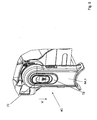
- the locking bracket 18 is secured in a pin 74 on the back shell 14 and engages with a nose 76, a back shell sleeve 78 which is integrally formed on the back shell 14.
- the nose 76 also passes through a seat shell sleeve 80, so that the seat shell 12 is fixed relative to the back shell 14.
- FIG. 7 shows the case that the locking bracket 18 is in a release position in which he no longer the seat shell sleeve 80 with his nose 76th be upheld. In this release position, the seat shell 12 is pivotable relative to the back shell 14 and can be adjusted.
- Via leaf springs 82.1, 82.2 causes the nose 76 engages in the radially next pocket 84 in the back shell sleeve 78, so that the seat shell 12 and the back shell 14 are again rotatably connected to each other.
- FIG. 8 shows the condition in which the tab 76 is latched into the pocket 84 in the back shell sleeve 78 as described above.
Landscapes
- Engineering & Computer Science (AREA)
- Chemical & Material Sciences (AREA)
- Combustion & Propulsion (AREA)
- Transportation (AREA)
- Mechanical Engineering (AREA)
- Health & Medical Sciences (AREA)
- Public Health (AREA)
- Carriages For Children, Sleds, And Other Hand-Operated Vehicles (AREA)
- Rehabilitation Tools (AREA)
- Paper (AREA)
- Window Of Vehicle (AREA)
- Optical Communication System (AREA)
Description
- Die Erfindung betrifft eine Kindersportkarre, insbesondere eine Rehabilitations-Kindersportkarre mit einem Gestell, einem Sitz und einer Schwenkvorrichtung, die den Sitz zumindest in Teilen mit dem Gestell um eine Sitz-Schwenkachse schwenkbar verbindet und ein erstes Gelenk und ein zweites Gelenk umfasst, die aufeinander gegenüber liegenden Seiten am Sitz angebracht sind, wobei das erste Gelenk und das zweite Gelenk arretierbar sind und wobei das erste Gelenk ein Erstgelenk-Bedienelement zum Lösen des ersten Gelenks umfasst.
- Derartige Rehabilitations-Kindersportkarren sind beispielsweise aus der
US 3,784,252 bekannt, um Kinder im Alter von zwei bis sechs Jahren, die körperlich behindert sind oder sich in der Rehabilitation nach einem ärztlichen Eingriff befinden, zu transportieren. Je nach Stimmung und Müdigkeitszustand des Kindes ist es vorteilhaft, den Rücken des Kindes unter verschiedene Winkel relativ zur Vertikalen neigen zu können. Dazu ist bei bekannten Rehabilitations-Kindersportkarren der Sitz geteilt ausgebildet und umfasst eine Rückenschale und eine Sitzschale. Die Rückenschale ist relativ zur Sitzschale verschwenkbar, so dass durch Neigen der Sitzschale der Rücken des Kindes unter verschiedenen Winkeln relativ zur Vertikalen gestützt wird, - Nachteilig an derartigen Rehabilitations-Kindersportkarren ist, dass dann, wenn die Rückenschale stark geneigt ist, ein stumpfer Winkel zwischen der Rückenschale und der Sitzschale entstehen kann. Hieraus resultiert eine hohe Belastung des Steißbeins des Kindes.
- Aus der
DE 20 2006 014 928 U1 ist ein Sportkinderwagen bekannt, dessen Sitz mittels eines Gelenks mit den Merkmalen des Oberbegriffs von Anspruch 1 schwenkbar ist. Nachteilig an dem beschriebenen Sportkinderwagen ist, dass das Bedienelement zum Lösen der Gelenke weit von den eigentlichen Gelenken beabstandet angeordnet ist. Es ergibt sich so eine umständliche Bedienung. - Aus der
US 6,086,086 ist ein Kinderwagen bekannt, bei dem der Sitz durch Betätigen eines Schalters verschoben werden kann. Aus derDE 10 2004 022 843 B4 ist ein Liegeeinsatz für Kinder- und/oder Puppenwagengestelle bekannt, bei dem das Rückenteil verschwenkbar ist. - Der Erfindung liegt die Aufgabe zugrunde, eine Rehabilitations-Kindersportkarre anzugeben, deren Sitz besonders einfach und leichtgängig arretierbar ist.
- Die Erfindung löst das Problem durch eine gattungsgemäße Kindersportkarre, insbesondere eine gattungsgemäße Rehabilitations-Kindersportkarre gemäß Anspruch 1.
- Vorteilhaft an der Erfindung ist, dass der Sitz als Ganzes um die Sitz-Schwenkachse schwenkbar ausgebildet ist. Eine Teilung des Sitzes in ein schwenkbares Rückenteil und ein feststehendes Sitzteil ist nämlich nur deshalb notwendig, damit das Kind nicht unkontrolliert verrutscht, wenn die Schwenkvorrichtung mit beiden Händen gelöst wird. Da aber erfindungsgemäß nur ein Erstgelenk-Bedienelement vorgesehen sein muss, um sowohl das erste Gelenk als auch das zweite Gelenk zu lösen, reicht eine Hand zum Lösen der Schwenkvorrichtung aus. Mit der verbleibenden zweiten Hand kann das Kind festgehalten werden und es besteht keine Gefahr, dass es unkontrolliert beispielsweise nach hinten überkippt. Da daher der Sitz integral mittels der Schwenkvorrichtung an dem Gestell befestigt ist, kommt es dann, wenn der Rücken stark gegenüber der Vertikalen geneigt ist, zu den nur geringen
- Kräften auf das Steißbein, da der Oberschenkel um den gleichen Betrag geschwenkt wird und so ein Gegengewicht bildet.
- Es ist ein weiterer Vorteil, dass die Erfindung mit mechanisch einfachen Mittel umsetzbar ist. Fehlfunktionen werden dadurch weitgehend vermieden.
- Ein weiterer Vorteil ist, dass das Kind in der Rehabilitations-Kindersportkarre während des Betätigens der Schwenkvorrichtung mit der Hand gehalten werden kann, so dass genau der Schwenkwinkel um die Sitz-Schwenkachse eingestellt werden kann, der den Wünschen des Kindes entspricht.
- Im Rahmen der vorliegenden Beschreibung wird unter einem Gestell insbesondere ein Rahmen verstanden, an dem auch Räder der Kindersportkarre befestigt sind. Unter einem Sitz wird jegliche Vorrichtung verstanden, die dazu ausgebildet ist, um unmittelbar das Gewicht eines Kindes aufzunehmen, das in der Kindersportkarre transportiert wird. Es ist dazu nicht notwendig, dass das Kind unmittelbar auf dieser Vorrichtung zum Sitzen kommt. Unter einem Sitz wird insbesondere auch eine Vorrichtung verstanden, auf die beispielsweise eine Sitzschale oder eine Polsterung montierbar ist
- Unter einer Übertragungsvorrichtung ist insbesondere jede Vorrichtung zu verstehen, die das Erstgelenk-Bedienelement mechanisch mit dem zweiten Gelenk koppelt. Diese Kopplung kann beispielsweise schubstabil, drehstabil oder dreh- und schubstabil ausgebildet sein.
- In einer bevorzugten Ausführungsform umfasst die Übertragungsvorrichtung eine Schubstange. Unter einer Schubstange wird insbesondere jedes Bauteil verstanden, das eine Kraft oder ein Drehmoment von dem Erstgelenk-Bedienelement auf das zweite Gelenk überträgt und mechanisch so steif ausgelegt ist, dass es sich dann, wenn das Erstgelenk-Bedienelement betätigt wird, so wenig verformt, dass das zweite Gelenk sicher gelöst wird. Vorteilhaft hieran ist, dass die Schubstange eine besonders einfache und kostengünstig herstellbare Übertragungsvorrichtung darstellt. Schubstangen sind zudem sehr wenig versagensanfällig.
- Besonders bevorzugt ist die Schubstange bogenförmig gebogen und in einer Betriebsstellung der Rehabilitations-Kindersportkarre zumindest teilweise unterhalb des Sitzes angeordnet. Dadurch wird erreicht, dass die Schubstange während des Betriebs nicht stört.
- Vorzugsweise sind das erste und das zweite Gelenk in eine Arretierstellung vorgespannt, in der der Sitz nicht relativ zum Gestell schwenkbar ist. Günstig ist es, wenn das erste und das zweite Gelenk voneinander unabhängig vorgespannt sind, beispielsweise durch Federn oder ähnliche Kraftspeicher. Hierdurch wird sichergestellt, dass die Schwenkvorrichtung das Gestell mit dem Sitz drehfest verbindet, sofern nicht das Erstgelenk-Bedienelement betätigt wird.
- In einer bevorzugten Ausführungsform ist das Erstgelenk-Bedienelement so ausgebildet, dass es eine Sicherungsstellung und eine Aktivierungsstellung besitzt und nur in der Aktivierungsstellung das erste Gelenk lösbar ist. Besonders bevorzugt ist das Erstgelenk-Bedienelement von der Sicherungsstellung in die Aktivierungsstellung schiebbar. Die Schieberichtung von der Sicherungsstellung in die Aktivierungsstellung verläuft bevorzugt im Wesentlichen senkrecht zu der Sitz-Schwenkachse. So wird eine besonders einfache Bedienung erreicht. Alternativ kann vorgesehen sein, dass das Erstgelenk-Bedienelement von der Sicherungsstellung in die Aktivierungsstellung drehbar ist.
- Bevorzugt ist, dass das erste Gelenk so ausgebildet ist, dass es dadurch lösbar ist, dass das Erstgelenk-Bedienelement in Richtung der Sitz-Schwenkachse, insbesondere auf den Sitz zu, bewegt wird. Es ergibt sich so eine besonders intuitive Bedienung des Erstgelenk-Bedienelements.
- Gemäß einer bevorzugten Ausführungsform ist vorgesehen, dass die Schubstange über eine Wippe auf ein Riegelelement des zweiten Gelenks wirkt. Das Riegelelement ist so angeordnet, dass es dann, wenn das Erstgelenk-Bedienelement nicht betätigt ist, das zweite Gelenk blockiert, das heißt an einer Schwenkbewegung hindert. Es ergibt sich so eine besonders eine einfache mechanische Ausbildung der Übertragungsvorrichtung.
- Um zu verhindern, dass die Schwenkvorrichtung selbsttätig freigegeben wird, ist gemäß einer bevorzugten Ausführungsform vorgesehen, dass das Erstgelenk-Bedienelement in die Sicherungsstellung vorgespannt ist. Eine Losbrechkraft, die notwendig ist, um das Erstgelenk-Bedienelement aus der Sicherungsstellung in die Aktivierungsstellung zu bewegen, ist bevorzugt so groß gewählt, dass sie von Kindern im Alter von zwei bis sechs Jahren nicht aufgebracht werden kann. Alternativ kann die Losbrechkraft auch so klein gewählt sein, dass sie mit einem Finger aufbringbar ist, da Kinder die Kombination aus zwei sukzessiven Bewegungen in der Regel nicht ausprobieren.
- Um die Schwenkvorrichtung von beiden Seiten der Kindersportkarre aus bedienbar zu machen, ist bevorzugt vorgesehen, dass das zweite Gelenk ein Zweitgelenk-Bedienelement zum Lösen des zweiten Gelenks besitzt, wobei das Zweitgelenk-Bedienelement mittels der Übertragungsvorrichtung so mit dem Erstgelenk verbunden ist, dass bei einem Lösen des zweiten Gelenks durch Betätigen des Zweitgelenk-Bedienelements auch das erste Gelenk gelöst wird.
- Im Folgenden wird die Erfindung anhand einer bevorzugten Ausführungsform näher erläutert. Dabei zeigt
- Figur 1
- eine perspektivische Ansicht eines Sitzes für eine erfindungsge- mäße Rehabilitations-Kindersportkarre,
- Figur 2
- ein Gestell, das mit dem Sitz nach
Figur 1 zu der erfindungsge- mäßen Rehabilitations-Kindersportkarre verbunden werden kann, - Figur 3
- eine schematische Schnittansicht durch den Sitz gemäß
Figur 1 , - Figur 4
- eine perspektivische Ansicht des Sitzes nach
Figur 1 , - Figur 5
- einen Ausschnitt aus
Figur 4 , - Figur 6
- eine geschnittene Seitenansicht durch ein Gelenk der Schwenkvorrichtung in einer Koppelstellung, bei der eine Relativ- Bewegung zwischen einer Rückenschale und einer Sitzschale des Sitzes gesperrt ist,
- Figur 7
- die geschnittene Ansicht gemäß
Figur 6 , bei der die Rückenschale gegenüber der Sitzschale verschwenkbar ist und - Figur 8
- die Schnittansicht gemäß den
Figuren 6 und7 , bei der die Rü- ckenschale in einer neuen Position relativ zur Sitzschale arretiert ist. -
Figur 1 zeigt, einen Sitz 10, der eine Sitzschale 12 und eine Rückenschale 14 umfasst. Die Sitzschale 12 ist an ihren beiden Seiten mit einer Schwenkvorrichtung 16 verbunden, so dass sie um eine Schwenkachse S verschwenkbar ist. Die Rückenschale 14 ist ebenfalls mit der Schwenkvorrichtung 16 um die Schwenkachse S schwenkbar verbunden. - An der Schwenkvorrichtung 16 ist zudem ein Arretierbügel 18 um die Schwenkachse S schwenkbar befestigt, der um die Rückenschale 14 herum verläuft, so dass eine im Sitz 10 sitzende Person nicht in Kontakt mit dem Arretierbügel 18 kommt. In
Figur 1 ist der Arretierbügel 18 in einer Koppelstellung gezeigt, in der die Rückenschale 14 relativ zur Sitzschale 12 fixiert ist. Der genaue Mechanismus hierzu ist weiter unten beschrieben. - Die Schwenkvorrichtung 16 umfasst ein erstes Gelenk 20 und ein zweites Gelenk 22, die beidseits von Sitzschale 12 und Rückenschale 14 angeordnet sind und jeweilige Anschlussstücke 24.1, 24.2 zum Verbinden mit einen Gestell besitzen. Die Schwenkvorrichtung 16 umfasst zudem Anschlusselemente 26.1, 26.2, die dazu ausgebildet sind, dass ein nicht eingezeichnetes Rückenrohr eingesteckt wird, an dem eine Sitzbespannung angebracht wird, die als Rückenlehne dient.
-
Figur 2 zeigt ein Gestell 28, das zwei Aufnahmestücke 30.1, 30.2 besitzt, die ausgebildet sind, um mit den Anschlussstücken 24.1, 24.2 (vgl.Figur 1 ) so zusammenzuwirken, dass der Sitz 10 mit dem Gestell 28 zu einer Rehabilitations-Kindersportkarre 32 verbunden kann. - Das Gestell 28 ist mit zwei Hinterrädern 34.1, 34.2 und zwei Vorderrädern 36.1, 36.2 verbunden. Das Gestell 28 umfasst zudem einen Schubbügel 38, mit dem die Rehabilitations-Kindersportkarre geschoben werden kann.
-
Figur 3 zeigt in einem schematischen Querschnitt den Sitz 10, wobei das zur Erläuterung irrelevante Zwischenteil des Sitzes herausgeschnitten ist. Das erste Gelenk 20 besitzt ein Erstgelenk-Bedienelement 40. Wird das Erstgelenk-Bedienelement 40 mit einer auf die Sitzschale 12 zu entlang der Schwenkachse S wirkenden Betätigungskraft F betätigt, so wird ein erster Läufer 42 entlang der Schwenkachse S nach innen verschoben und gelangt so außer Eingriff aus einer Verzahnungseinheit 44, die mit der Sitzschale 12 gekoppelt ist. Damit wird der Läufer 42 um die Schwenkachse S relativ zu der Verzahnungseinheit 44 und damit relativ zum Anschlussstück 24.1 schwenkbar. - Durch Aufbringen der Betätigungskraft F auf das Erstgelenk-Bedienelement 40 wird zudem eine Schubstange 46 entlang der Schwenkachse S in Richtung eines Pfeils P verschoben. Dazu ist ein erstes Ende 48 der Schubstange 46 mit dem Erstgelenk-Bedienelement 40 fest verbunden.
- Bewegt sich die Schubstange 46 in Richtung des Pfeils P, so drückt ein dem ersten Ende 48 abgewandtes zweites Ende 50 der Schubstange 46 auf eine Wippe 52, die relativ zu dem Anschlussstück 24.2 in einer Auflagerstelle 54 gelagert ist. Dadurch schwenkt ein bezüglich der Auflagerstelle 54 von der Schubstange 46 abgewandtes Ende auf eines zweiten Läufers 56 zu und bewegt diesen entlang der Schwenkachse S nach innen. Der Begriff "innen" bezieht sich dabei auf den Sitz 10 als Ganzes.
- Der zweite Läufer 56 ist über eine Feder 58 in eine Arretierstellung vorgespannt. Auf gleiche Weise ist der erste Läufer 42 über eine Feder 59 in eine Arretierstellung vorgespannt. Indirekt drückt die Federkraft der Feder 58 über die Wippe 52 und die Schubstange 46 das Erstgelenk-Bedienelement 40 in eine Ausgangsstellung, in der die Läufer 56, 42 in Arretierstellung sind und in der sowohl das erste Gelenk 20 als auch das zweite Gelenk 22 drehstarr arretiert sind. Wird das Erstgelenk-Bedienelement 40 mit der Betätigungskraft F beaufschlagt, so kommt ein Koppelement 60 außer Eingriff mit einem Widerlager 62, so dass die Sitzschale 12 und die Rückenschale 14 relativ zueinander gekoppelt um die Schwenkachse S schwenken können.
-
Figur 4 zeigt eine perspektivische Ansicht des Sitzes 10, in der die Erstgelenk-Bedieneinheit 40 leichter zu sehen ist. Die Erstgelenk-Bedieneinheit 40 ist ausgebildet, dass sie eine inFigur 4 gezeigte Sicherungsstellung besitzt. In dieser Sicherungsstellung liegt das Erstgelenk-Bedienelement 40 so auf einem Gehäuse 64.1 auf, dass es auch beim Aufbringen der Betätigungskraft F nicht entlang der Schwenkachse S bewegbar ist. - Durch Schieben eines Sicherungsschiebers 70 des Erstgelenk-Bedienelements 40 in eine Verschieberrichtung V, die im Wesentlichen senkrecht zur Schwenkachse S verläuft, wird das Erstgelenk-Bedienelement 40 in eine Aktivierungsstellung gebracht, in der das erste Gelenk 20 und das zweite Gelenk 22 wie oben beschrieben durch Aufbringen der Betätigungskraft F auf einen Schubknopf 72 des Erstgelenk-Bedienelements 40 gelöst werden können. Durch eine Spiralfeder 66 ist das Erstgelenk-Bedienelement 40 in die in
Figur 4 gezeigt Sicherungsstellung vorgespannt.Figur 4 zeigt zudem eine Fußauflage 68, die an der Sitzschale 12 montiert ist. - In
Figur 5 ist ein Ausschnitt ausFigur 4 gezeigt. Es ist zu erkennen, dass das Erstgelenk-Bedienelement 40 einen Sicherungsschieber 70 und einen Schubknopf 72 umfasst. Wird der Sicherungsschieber 70 in Verschieberichtung V, inFigur 5 nach unten, geschoben, so wird das Erstgelenk-Bedienelement 40 dadurch freigegeben, dass anschließend sowohl der Sicherungsschieber 70 als auch der Schubknopf 72 in das Gehäuse 64.1 eingedrückt werden können. Der Sicherungsschieber 70 ist relativ zum Schubknopf 72 wie oben beschrieben vorgespannt. -
Figur 6 zeigt einen Schnitt entlang der Linie A-A gemäßFigur 3 durch das zweite Gelenk 22. Der Arretierbügel 18 ist in einem Zapfen 74 an der Rückenschale 14 befestigt und durchgreift mit einer Nase 76 eine Rückenschalen-Hülse 78, die einstückig an der Rückenschale 14 ausgebildet ist. In einer inFigur 6 gezeigten Koppelstellung durchgreift die Nase 76 zudem eine Sitzschalen-Hülse 80, so dass die Sitzschale 12 relativ zur Rückenschale 14 festgelegt ist. -
Figur 7 zeigt den Fall, dass sich der Arretierbügel 18 in einer Freigabestellung befindet, in der er die Sitzschalen-Hülse 80 nicht mehr mit seiner Nase 76 durchgreift. In dieser Freigabestellung ist die Sitzschale 12 relativ zur Rückenschale 14 schwenkbar und kann verstellt werden. - Über Blattfedern 82.1, 82.2 wird bewirkt, dass die Nase 76 in die radial nächste Tasche 84 in der Rückenschalenhülse 78 eingreift, so dass die Sitzschale 12 und die Rückenschale 14 erneut miteinander drehfest verbunden sind.
-
Figur 8 zeigt den Zustand, in dem die Nase 76 wie oben beschrieben in die Tasche 84 in der Rückenschalen-Hülse 78 eingerastet ist. -
- 10
- Sitz
- 12
- Sitzschale
- 14
- Rückenschale
- 16
- Schwenkvorrichtung
- 18
- Arretierbügel
- 20
- erstes Gelenk
- 22
- zweites Gelenk
- 24.1, .2
- Anschlussstück
- 26.1, .2
- Anschlusselement
- 28
- Gestell
- 30.1, .2
- Aufnahmestück
- 32
- Rehabilitations- Kindersportkarre
- 34
- Hinterrad
- 36
- Vorderrad
- 38
- Schubbügel
- 40
- Erstgelenk- Bedienelement
- 42
- Läufer
- 44
- Verzahnungseinheit
- 46
- Schubstange
- 48
- erstes Ende
- 50
- zweites Ende
- 52
- Wippe
- 54
- Auflagerstelle
- 56
- zweiter Läufer
- 58
- Feder
- 59
- Feder
- 60
- Riegelelement
- 62
- Widerlager
- 64
- Gehäuse
- 66
- Spiralfeder
- 68
- Fußauflage
- 70
- Sicherungsschieber
- 72
- Schubknopf
- 74
- Zapfen
- 76
- Nase
- 78
- Rückenschalen- Hülse
- 80
- Sitzschalen-Hülse
- 82.1, .2
- Blattfeder
- 84
- Tasche
- S
- Schwenkachse
- F
- Betätigungskraft
- P
- Pfeil
- V
- Verschieberichtung
Claims (12)
- Rehabilitations-Kindersportkarre mit(a) einem Gestell (28),(b) einem Sitz (10) und(c) einer Schwenkvorrichtung (16), die(i) den Sitz (10) zumindest in Teilen mit dem Gestell (28) um eine Sitz-Schwenkachse (S) schwenkbar verbindet und(ii) ein erstes Gelenk (20) und ein zweites Gelenk (22) umfasst, die auf einander gegenüber liegenden Seiten am Sitz (10) angebracht sind,(iii) wobei das erste Gelenk (20) und das zweite Gelenk (22) arretierbar sind,(d) wobei das erste Gelenk (20) ein Erstgelenk-Bedienelement (40) zum Lösen des ersten Gelenks (20) umfasst,(e) wobei das zweite Gelenk (22) mittels einer schubstabilen Übertragungsvorrichtung mit dem Erstgelenk-Bedienelement (40) so verbunden ist, dass bei einem Betätigen des Erstgetenk-Bedienelements (40) das erste Gelenk (20) und das zweite Gelenk (22) gelöst werden und(f) wobei das zweite Gelenk (22) ein Zweitgelenk-Bedienelement zum Arretieren und Lösen des zweiten Gelenks (22) besitzt, wobei das Zweitgelenk-Bedienelement mittels der schubstabilen Übertragungsvorrichtung (46) so mit dem ersten Gelenk (20) verbunden ist, dass bei einem Lösen des zweiten Gelenks (22) das erste Gelenk (20) gelöst wird,
dadurch gekennzeichnet, dass(g) der Sitz integral mittels der Schwenkvorrichtung (16) an dem Gestell (28) befestigt ist. - Rehabilitations-Kindersportkarre nach Anspruch 1, dadurch gekennzeichnet, dass die Übertragungsvorrichtung eine Schubstange (46) umfasst.
- Rehabilitations-Kindersportkarre nach Anspruch 2, dadurch gekennzeichnet, dass die Schubstange (46) bogenförmig gebogen ist und in einer Betriebsstellung der Rehabilitations-Kindersportkarre (32) zumindest teilweise unterhalb des Sitzes (10) verläuft.
- Rehabilitations-Kindersportkarre nach einem der vorstehenden Ansprüche, dadurch gekennzeichnet, dass das erste Gelenk (20) und das zweite Gelenk (22) in eine Arretierstellung vorgespannt sind.
- Rehabilitations-Kindersportkarre nach einem der vorstehenden Ansprüche, dadurch gekennzeichnet, dass das Erstgelenk-Bedienelement (40) so ausgebildet ist, dass es- eine Sicherungsstellung und eine Aktivierungsstellung besitzt und- nur in der Aktivierungsstellung das erste Gelenk (20) zu lösen ist.
- Rehabilitations-Kindersportkarre nach Anspruch 5, dadurch gekennzeichnet, dass das Erstgelenk-Bedienelement (40) von der Sicherungsstellung in die Aktivierungsstellung schiebbar ist.
- Rehabilitations-Kindersportkarre nach Anspruch 6, dadurch gekennzeichnet, dass das Erstgelenk-Bedienelement (40)- einen Schubknopf (72) und- einen am Schubknopf (72) angebrachten Sicherungsschieber (70), der im Wesentlichen senkrecht zu der Schwenkachse (S) von der Sicherungsstellung in die Aktivierungsstellung schiebbar ist,umfasst.
- Rehabilitations-Kindersportkarre nach Anspruch 5 bis 7, dadurch gekennzeichnet, dass das erste Gelenk (20) durch eine translatorische Bewegung des in der Aktivierungsstellung befindlichen Erstgelenk-Bedienelements (40) in Richtung der Sitz-Schwenkachse lösbar ausgebildet ist.
- Rehabilitations-Kindersportkarre nach Anspruch 8, dadurch gekennzeichnet, dass die Schubstange (46) über eine Wippe (52) auf ein Riegelelement (60) des zweiten Gelenks (22) wirkt.
- Rehabititations-Kindersportkarre nach einem der Ansprüche 5 bis 9, dadurch gekennzeichnet, dass Erstgelenk-Bedienelement (40) in die Sicherungsstellung vorgespannt ist.
- Rehabilitations-Kindersportkarre nach einem der vorstehenden Ansprüche, dadurch gekennzeichnet, dass- der Sitz (10) eine Sitzschale (12), eine Rückenschale (14) und einen Arretierbügel (18) umfasst,- wobei die Schwenkvorrichtung (16) so ausgebildet ist, dass der Arretierbügel (18) eine Koppelstellung, in der die Rückenschale (14) relativ zur Sitzschale (12) fixiert ist, und eine Freigabestellung, in der die Rückenschale (14) relativ zur Sitzschale (12) verschwenkbar ist, aufweist.
- Rehabilitations-Kindersportkarre nach Anspruch 11, dadurch gekennzeichnet, dass die Schwenkvorrichtung so ausgebildet ist, dass dann, wenn- der Arretierbügel (18) in der Koppelstellung ist und- das Erstgelenk-Bedienelement (40) betätigt ist,die Sitzschale (12) und die Rückenschale (14) im relativ zueinander fixierten Zustand um die Schwenkachse (S) schwenkbar sind.
Applications Claiming Priority (2)
| Application Number | Priority Date | Filing Date | Title |
|---|---|---|---|
| DE102007044833A DE102007044833A1 (de) | 2007-09-18 | 2007-09-18 | Kindersportkarre |
| PCT/DE2008/001487 WO2009036734A1 (de) | 2007-09-18 | 2008-09-03 | Kindersportkarre |
Publications (2)
| Publication Number | Publication Date |
|---|---|
| EP2197726A1 EP2197726A1 (de) | 2010-06-23 |
| EP2197726B1 true EP2197726B1 (de) | 2011-01-12 |
Family
ID=40225444
Family Applications (1)
| Application Number | Title | Priority Date | Filing Date |
|---|---|---|---|
| EP08801294A Not-in-force EP2197726B1 (de) | 2007-09-18 | 2008-09-03 | Kindersportkarre |
Country Status (7)
| Country | Link |
|---|---|
| US (1) | US8205906B2 (de) |
| EP (1) | EP2197726B1 (de) |
| CN (1) | CN101835670B (de) |
| AT (1) | ATE495078T1 (de) |
| DE (2) | DE102007044833A1 (de) |
| RU (1) | RU2010115342A (de) |
| WO (1) | WO2009036734A1 (de) |
Families Citing this family (21)
| Publication number | Priority date | Publication date | Assignee | Title |
|---|---|---|---|---|
| US20100052277A1 (en) * | 2008-09-04 | 2010-03-04 | Dynamic Brands, Llc | Stroller accessory |
| AU2010238191A1 (en) | 2009-04-16 | 2011-11-17 | Doona Holdings Ltd. | Baby safety car seat convertible into a rollable baby seat |
| CN101780806B (zh) * | 2010-02-11 | 2013-01-23 | 中山市隆成日用制品有限公司 | 以手把操作座椅换向的婴儿车 |
| CN103496392B (zh) * | 2010-12-20 | 2016-03-02 | 明门香港股份有限公司 | 婴儿承载装置 |
| US8905428B2 (en) | 2011-03-21 | 2014-12-09 | Graco Children's Products Inc. | Foldable stroller and fold joint for a foldable stroller |
| US8961057B2 (en) | 2011-12-18 | 2015-02-24 | Graco Children's Products Inc. | Fold latch and fold joint for a stroller |
| US9216755B2 (en) * | 2012-03-30 | 2015-12-22 | Kolcraft Enterprises, Inc. | Foldable strollers |
| US9242585B2 (en) * | 2012-06-05 | 2016-01-26 | Micheal Kozinski | Infant car seat assembly |
| WO2013184825A1 (en) * | 2012-06-05 | 2013-12-12 | Kozinski Micheal | Infant car seat assembly |
| EP2684768B1 (de) | 2012-07-13 | 2019-03-13 | Thule Child Transport Systems Ltd | Passagierträger mit zusätzlicher Querstange |
| EP2684766B1 (de) * | 2012-07-13 | 2018-07-04 | Thule Child Transport Systems Ltd | Zusammenklappbarer Passagierträger |
| USD704600S1 (en) | 2012-12-21 | 2014-05-13 | Thule Child Transport Systems Ltd. | Passenger carriage device |
| US9399477B2 (en) | 2012-12-27 | 2016-07-26 | Kolcraft Enterprises, Inc. | Strollers with removable child supports and related methods |
| IL228492A (en) | 2013-09-17 | 2016-11-30 | Doona Holdings Ltd | A baby safety seat that can be made into a portable baby chair |
| EP2871112B1 (de) | 2013-11-01 | 2017-10-11 | Thule Child Transport Systems Ltd | Zusammenklappbarer Wagen |
| US10994763B2 (en) * | 2016-07-27 | 2021-05-04 | Kolcraft Enterprises, Inc. | Foldable strollers with removeable seats and related methods |
| EP3490874A4 (de) | 2016-07-27 | 2020-04-15 | Kolcraft Enterprises, Inc. | Zusammenklappbare kinderwagen und zugehörige verfahren |
| US11059510B2 (en) | 2016-07-27 | 2021-07-13 | Kolcraft Enterprises, Inc. | Strollers with removable seats and related methods |
| EP3363711A1 (de) * | 2017-02-14 | 2018-08-22 | Dorel France | Kinderwagen, der einen abnehmbaren zusatzsitz umfasst, und entsprechender zusatzsitz |
| WO2019019097A1 (en) | 2017-07-27 | 2019-01-31 | Kolcraft Enterprises,Inc. | PUSHABLE STROLLERS AND ASSOCIATED METHODS |
| US12691922B2 (en) * | 2023-07-21 | 2026-07-28 | Monahan Products, LLC | Control mechanism for foldable stroller |
Family Cites Families (11)
| Publication number | Priority date | Publication date | Assignee | Title |
|---|---|---|---|---|
| US3784252A (en) | 1971-12-27 | 1974-01-08 | Peterson Baby Prod Co | Seat back adjustment mechanism for baby products |
| JPH0775984B2 (ja) | 1990-10-05 | 1995-08-16 | コンビ株式会社 | ベビーカーのリクライニング若しくは倒伏機構 |
| US5257799A (en) | 1991-10-04 | 1993-11-02 | Cosco, Inc. | Foldable stroller |
| US5794951A (en) * | 1996-10-25 | 1998-08-18 | Century Products Company | Child's stroller with manually operable accessory latch assembly |
| US6086086A (en) * | 1999-05-11 | 2000-07-11 | Sunrise Medical Hhg Inc. | Stroller with tilt-in-space capability |
| DE20308018U1 (de) * | 2003-05-22 | 2003-07-31 | Beger, Udo, 84030 Ergolding | Sitz/Liegeeinsatz für Kinder- und/oder Puppenwagengestelle |
| US7367581B2 (en) * | 2005-08-26 | 2008-05-06 | Link Treasure Limited | Baby stroller frame with seat direction changing mechanism |
| TWM288269U (en) * | 2005-09-29 | 2006-03-01 | Link Treasure Ltd | One-hand controlled seat inclination structure for baby trolley |
| TWM290119U (en) * | 2005-10-14 | 2006-05-01 | Link Treasure Ltd | Framework structure of stroller |
| US8251382B2 (en) * | 2007-06-06 | 2012-08-28 | Wonderland Nurserygoods Co., Ltd. | Stroller and seat assembly mechanism for a stroller |
| US8128119B2 (en) * | 2007-07-31 | 2012-03-06 | Graco Children's Products Inc. | Stroller with foldable frame and adjustable handle |
-
2007
- 2007-09-18 DE DE102007044833A patent/DE102007044833A1/de not_active Withdrawn
-
2008
- 2008-09-03 AT AT08801294T patent/ATE495078T1/de active
- 2008-09-03 RU RU2010115342/11A patent/RU2010115342A/ru unknown
- 2008-09-03 DE DE502008002343T patent/DE502008002343D1/de active Active
- 2008-09-03 WO PCT/DE2008/001487 patent/WO2009036734A1/de not_active Ceased
- 2008-09-03 CN CN2008801124216A patent/CN101835670B/zh not_active Expired - Fee Related
- 2008-09-03 EP EP08801294A patent/EP2197726B1/de not_active Not-in-force
- 2008-09-03 US US12/678,731 patent/US8205906B2/en not_active Expired - Fee Related
Also Published As
| Publication number | Publication date |
|---|---|
| WO2009036734A1 (de) | 2009-03-26 |
| US20100201103A1 (en) | 2010-08-12 |
| US8205906B2 (en) | 2012-06-26 |
| CN101835670B (zh) | 2012-08-22 |
| DE102007044833A1 (de) | 2009-04-02 |
| DE502008002343D1 (de) | 2011-02-24 |
| ATE495078T1 (de) | 2011-01-15 |
| EP2197726A1 (de) | 2010-06-23 |
| CN101835670A (zh) | 2010-09-15 |
| RU2010115342A (ru) | 2011-10-27 |
Similar Documents
| Publication | Publication Date | Title |
|---|---|---|
| EP2197726A1 (de) | Kindersportkarre | |
| DE102007045068B3 (de) | Kinder-Sportkarre | |
| EP3172111B1 (de) | Kinderwagen | |
| DE60212779T2 (de) | Fahrzeugsitz mit vorklappbarer Rückenlehne | |
| DE102009048649B4 (de) | Mit einem Autositz verbindbarer Kinderwagen | |
| EP3261901B1 (de) | Zusammenklappbarer kindersitz sowie kinderwagen mit einem solchen kindersitz | |
| DE2823086C2 (de) | Kinderwagen mit einer für beide Fahrtrichtungen umstellbaren Schiebevorrichtung | |
| DE69402184T2 (de) | Faltbare einheit zum tragen oder transport einer person | |
| DE19643424C2 (de) | Faltmechanismus für Kinder-Sportwagen | |
| DE2709848C3 (de) | Zusammenlegbarer Kinderwagen | |
| DE60200063T2 (de) | Klappbarer Kinderwagen | |
| DE69928737T2 (de) | Zusammenklappbarer Kinderwagen mit schwenkbarem Griff und fernbedienbare Faltvorrichtung | |
| DE3782377T2 (de) | Klappbarer kinderwagen. | |
| DE2627731C2 (de) | Zusammenklappbarer Kinderwagen | |
| DE3018160A1 (de) | Zusammenklappbarer wagen zur befoerderung von kleinkindern | |
| DE3522285A1 (de) | Fahrzeugsitz | |
| CH664121A5 (de) | Zusammenfaltbarer kindersportwagen. | |
| EP2271537B1 (de) | Zusammenklappbarer schiebewagen für kinder und/oder puppen | |
| DE202005013397U1 (de) | Einhandbedienungsvorrichtung für Kinderkarre | |
| DE3225546C2 (de) | ||
| DE202021105009U1 (de) | Kinderwagen zum einfachen Vorwärts- und Rückwärtsfalten | |
| DE3540642C2 (de) | ||
| EP3172112A1 (de) | Kinderwagen | |
| DE4226090A1 (de) | Radfeststellvorrichtung, insbesondere für Kinderwagen | |
| DE202005019055U1 (de) | Mehrzweckkinderwagen |
Legal Events
| Date | Code | Title | Description |
|---|---|---|---|
| PUAI | Public reference made under article 153(3) epc to a published international application that has entered the european phase |
Free format text: ORIGINAL CODE: 0009012 |
|
| 17P | Request for examination filed |
Effective date: 20100316 |
|
| AK | Designated contracting states |
Kind code of ref document: A1 Designated state(s): AT BE BG CH CY CZ DE DK EE ES FI FR GB GR HR HU IE IS IT LI LT LU LV MC MT NL NO PL PT RO SE SI SK TR |
|
| AX | Request for extension of the european patent |
Extension state: AL BA MK RS |
|
| GRAP | Despatch of communication of intention to grant a patent |
Free format text: ORIGINAL CODE: EPIDOSNIGR1 |
|
| GRAS | Grant fee paid |
Free format text: ORIGINAL CODE: EPIDOSNIGR3 |
|
| GRAA | (expected) grant |
Free format text: ORIGINAL CODE: 0009210 |
|
| DAX | Request for extension of the european patent (deleted) | ||
| AK | Designated contracting states |
Kind code of ref document: B1 Designated state(s): AT BE BG CH CY CZ DE DK EE ES FI FR GB GR HR HU IE IS IT LI LT LU LV MC MT NL NO PL PT RO SE SI SK TR |
|
| REG | Reference to a national code |
Ref country code: GB Ref legal event code: FG4D Free format text: NOT ENGLISH |
|
| REG | Reference to a national code |
Ref country code: CH Ref legal event code: EP |
|
| REG | Reference to a national code |
Ref country code: IE Ref legal event code: FG4D Free format text: LANGUAGE OF EP DOCUMENT: GERMAN |
|
| REF | Corresponds to: |
Ref document number: 502008002343 Country of ref document: DE Date of ref document: 20110224 Kind code of ref document: P |
|
| REG | Reference to a national code |
Ref country code: DE Ref legal event code: R096 Ref document number: 502008002343 Country of ref document: DE Effective date: 20110224 |
|
| REG | Reference to a national code |
Ref country code: NL Ref legal event code: VDEP Effective date: 20110112 |
|
| LTIE | Lt: invalidation of european patent or patent extension |
Effective date: 20110112 |
|
| PG25 | Lapsed in a contracting state [announced via postgrant information from national office to epo] |
Ref country code: PT Free format text: LAPSE BECAUSE OF FAILURE TO SUBMIT A TRANSLATION OF THE DESCRIPTION OR TO PAY THE FEE WITHIN THE PRESCRIBED TIME-LIMIT Effective date: 20110512 Ref country code: IS Free format text: LAPSE BECAUSE OF FAILURE TO SUBMIT A TRANSLATION OF THE DESCRIPTION OR TO PAY THE FEE WITHIN THE PRESCRIBED TIME-LIMIT Effective date: 20110512 Ref country code: NO Free format text: LAPSE BECAUSE OF FAILURE TO SUBMIT A TRANSLATION OF THE DESCRIPTION OR TO PAY THE FEE WITHIN THE PRESCRIBED TIME-LIMIT Effective date: 20110412 Ref country code: LT Free format text: LAPSE BECAUSE OF FAILURE TO SUBMIT A TRANSLATION OF THE DESCRIPTION OR TO PAY THE FEE WITHIN THE PRESCRIBED TIME-LIMIT Effective date: 20110112 Ref country code: HR Free format text: LAPSE BECAUSE OF FAILURE TO SUBMIT A TRANSLATION OF THE DESCRIPTION OR TO PAY THE FEE WITHIN THE PRESCRIBED TIME-LIMIT Effective date: 20110112 Ref country code: SE Free format text: LAPSE BECAUSE OF FAILURE TO SUBMIT A TRANSLATION OF THE DESCRIPTION OR TO PAY THE FEE WITHIN THE PRESCRIBED TIME-LIMIT Effective date: 20110112 Ref country code: ES Free format text: LAPSE BECAUSE OF FAILURE TO SUBMIT A TRANSLATION OF THE DESCRIPTION OR TO PAY THE FEE WITHIN THE PRESCRIBED TIME-LIMIT Effective date: 20110423 Ref country code: GR Free format text: LAPSE BECAUSE OF FAILURE TO SUBMIT A TRANSLATION OF THE DESCRIPTION OR TO PAY THE FEE WITHIN THE PRESCRIBED TIME-LIMIT Effective date: 20110413 Ref country code: LV Free format text: LAPSE BECAUSE OF FAILURE TO SUBMIT A TRANSLATION OF THE DESCRIPTION OR TO PAY THE FEE WITHIN THE PRESCRIBED TIME-LIMIT Effective date: 20110112 |
|
| REG | Reference to a national code |
Ref country code: IE Ref legal event code: FD4D |
|
| PG25 | Lapsed in a contracting state [announced via postgrant information from national office to epo] |
Ref country code: FI Free format text: LAPSE BECAUSE OF FAILURE TO SUBMIT A TRANSLATION OF THE DESCRIPTION OR TO PAY THE FEE WITHIN THE PRESCRIBED TIME-LIMIT Effective date: 20110112 Ref country code: CY Free format text: LAPSE BECAUSE OF FAILURE TO SUBMIT A TRANSLATION OF THE DESCRIPTION OR TO PAY THE FEE WITHIN THE PRESCRIBED TIME-LIMIT Effective date: 20110112 Ref country code: NL Free format text: LAPSE BECAUSE OF FAILURE TO SUBMIT A TRANSLATION OF THE DESCRIPTION OR TO PAY THE FEE WITHIN THE PRESCRIBED TIME-LIMIT Effective date: 20110112 Ref country code: PL Free format text: LAPSE BECAUSE OF FAILURE TO SUBMIT A TRANSLATION OF THE DESCRIPTION OR TO PAY THE FEE WITHIN THE PRESCRIBED TIME-LIMIT Effective date: 20110112 Ref country code: SI Free format text: LAPSE BECAUSE OF FAILURE TO SUBMIT A TRANSLATION OF THE DESCRIPTION OR TO PAY THE FEE WITHIN THE PRESCRIBED TIME-LIMIT Effective date: 20110112 Ref country code: BG Free format text: LAPSE BECAUSE OF FAILURE TO SUBMIT A TRANSLATION OF THE DESCRIPTION OR TO PAY THE FEE WITHIN THE PRESCRIBED TIME-LIMIT Effective date: 20110412 |
|
| PG25 | Lapsed in a contracting state [announced via postgrant information from national office to epo] |
Ref country code: EE Free format text: LAPSE BECAUSE OF FAILURE TO SUBMIT A TRANSLATION OF THE DESCRIPTION OR TO PAY THE FEE WITHIN THE PRESCRIBED TIME-LIMIT Effective date: 20110112 Ref country code: DK Free format text: LAPSE BECAUSE OF FAILURE TO SUBMIT A TRANSLATION OF THE DESCRIPTION OR TO PAY THE FEE WITHIN THE PRESCRIBED TIME-LIMIT Effective date: 20110112 Ref country code: IE Free format text: LAPSE BECAUSE OF FAILURE TO SUBMIT A TRANSLATION OF THE DESCRIPTION OR TO PAY THE FEE WITHIN THE PRESCRIBED TIME-LIMIT Effective date: 20110112 |
|
| PLBE | No opposition filed within time limit |
Free format text: ORIGINAL CODE: 0009261 |
|
| STAA | Information on the status of an ep patent application or granted ep patent |
Free format text: STATUS: NO OPPOSITION FILED WITHIN TIME LIMIT |
|
| PG25 | Lapsed in a contracting state [announced via postgrant information from national office to epo] |
Ref country code: RO Free format text: LAPSE BECAUSE OF FAILURE TO SUBMIT A TRANSLATION OF THE DESCRIPTION OR TO PAY THE FEE WITHIN THE PRESCRIBED TIME-LIMIT Effective date: 20110112 Ref country code: SK Free format text: LAPSE BECAUSE OF FAILURE TO SUBMIT A TRANSLATION OF THE DESCRIPTION OR TO PAY THE FEE WITHIN THE PRESCRIBED TIME-LIMIT Effective date: 20110112 Ref country code: CZ Free format text: LAPSE BECAUSE OF FAILURE TO SUBMIT A TRANSLATION OF THE DESCRIPTION OR TO PAY THE FEE WITHIN THE PRESCRIBED TIME-LIMIT Effective date: 20110112 |
|
| 26N | No opposition filed |
Effective date: 20111013 |
|
| REG | Reference to a national code |
Ref country code: DE Ref legal event code: R097 Ref document number: 502008002343 Country of ref document: DE Effective date: 20111013 |
|
| BERE | Be: lapsed |
Owner name: OTTO BOCK HEALTHCARE G.M.B.H. Effective date: 20110930 |
|
| PG25 | Lapsed in a contracting state [announced via postgrant information from national office to epo] |
Ref country code: MC Free format text: LAPSE BECAUSE OF NON-PAYMENT OF DUE FEES Effective date: 20110930 |
|
| REG | Reference to a national code |
Ref country code: FR Ref legal event code: ST Effective date: 20120531 |
|
| PG25 | Lapsed in a contracting state [announced via postgrant information from national office to epo] |
Ref country code: BE Free format text: LAPSE BECAUSE OF NON-PAYMENT OF DUE FEES Effective date: 20110930 |
|
| PG25 | Lapsed in a contracting state [announced via postgrant information from national office to epo] |
Ref country code: FR Free format text: LAPSE BECAUSE OF NON-PAYMENT OF DUE FEES Effective date: 20110930 |
|
| PG25 | Lapsed in a contracting state [announced via postgrant information from national office to epo] |
Ref country code: MT Free format text: LAPSE BECAUSE OF FAILURE TO SUBMIT A TRANSLATION OF THE DESCRIPTION OR TO PAY THE FEE WITHIN THE PRESCRIBED TIME-LIMIT Effective date: 20110112 |
|
| REG | Reference to a national code |
Ref country code: CH Ref legal event code: PL |
|
| PG25 | Lapsed in a contracting state [announced via postgrant information from national office to epo] |
Ref country code: LU Free format text: LAPSE BECAUSE OF NON-PAYMENT OF DUE FEES Effective date: 20110903 |
|
| PG25 | Lapsed in a contracting state [announced via postgrant information from national office to epo] |
Ref country code: LI Free format text: LAPSE BECAUSE OF NON-PAYMENT OF DUE FEES Effective date: 20120930 Ref country code: CH Free format text: LAPSE BECAUSE OF NON-PAYMENT OF DUE FEES Effective date: 20120930 |
|
| PG25 | Lapsed in a contracting state [announced via postgrant information from national office to epo] |
Ref country code: TR Free format text: LAPSE BECAUSE OF FAILURE TO SUBMIT A TRANSLATION OF THE DESCRIPTION OR TO PAY THE FEE WITHIN THE PRESCRIBED TIME-LIMIT Effective date: 20110112 |
|
| PG25 | Lapsed in a contracting state [announced via postgrant information from national office to epo] |
Ref country code: HU Free format text: LAPSE BECAUSE OF FAILURE TO SUBMIT A TRANSLATION OF THE DESCRIPTION OR TO PAY THE FEE WITHIN THE PRESCRIBED TIME-LIMIT Effective date: 20110112 |
|
| REG | Reference to a national code |
Ref country code: AT Ref legal event code: MM01 Ref document number: 495078 Country of ref document: AT Kind code of ref document: T Effective date: 20130903 |
|
| PG25 | Lapsed in a contracting state [announced via postgrant information from national office to epo] |
Ref country code: AT Free format text: LAPSE BECAUSE OF NON-PAYMENT OF DUE FEES Effective date: 20130903 |
|
| REG | Reference to a national code |
Ref country code: DE Ref legal event code: R082 Ref document number: 502008002343 Country of ref document: DE Representative=s name: GRAMM, LINS & PARTNER PATENT- UND RECHTSANWAEL, DE |
|
| REG | Reference to a national code |
Ref country code: DE Ref legal event code: R082 Ref document number: 502008002343 Country of ref document: DE Representative=s name: GRAMM, LINS & PARTNER PATENT- UND RECHTSANWAEL, DE Ref country code: DE Ref legal event code: R081 Ref document number: 502008002343 Country of ref document: DE Owner name: OTTOBOCK SE & CO. KGAA, DE Free format text: FORMER OWNER: OTTO BOCK HEALTHCARE GMBH, 37115 DUDERSTADT, DE |
|
| PGFP | Annual fee paid to national office [announced via postgrant information from national office to epo] |
Ref country code: GB Payment date: 20220927 Year of fee payment: 15 |
|
| PGFP | Annual fee paid to national office [announced via postgrant information from national office to epo] |
Ref country code: IT Payment date: 20220930 Year of fee payment: 15 |
|
| PGFP | Annual fee paid to national office [announced via postgrant information from national office to epo] |
Ref country code: DE Payment date: 20230919 Year of fee payment: 16 |
|
| GBPC | Gb: european patent ceased through non-payment of renewal fee |
Effective date: 20230903 |
|
| PG25 | Lapsed in a contracting state [announced via postgrant information from national office to epo] |
Ref country code: GB Free format text: LAPSE BECAUSE OF NON-PAYMENT OF DUE FEES Effective date: 20230903 |
|
| PG25 | Lapsed in a contracting state [announced via postgrant information from national office to epo] |
Ref country code: GB Free format text: LAPSE BECAUSE OF NON-PAYMENT OF DUE FEES Effective date: 20230903 |
|
| PG25 | Lapsed in a contracting state [announced via postgrant information from national office to epo] |
Ref country code: IT Free format text: LAPSE BECAUSE OF NON-PAYMENT OF DUE FEES Effective date: 20230903 |
|
| PG25 | Lapsed in a contracting state [announced via postgrant information from national office to epo] |
Ref country code: IT Free format text: LAPSE BECAUSE OF NON-PAYMENT OF DUE FEES Effective date: 20230903 |
|
| REG | Reference to a national code |
Ref country code: DE Ref legal event code: R119 Ref document number: 502008002343 Country of ref document: DE |
|
| PG25 | Lapsed in a contracting state [announced via postgrant information from national office to epo] |
Ref country code: DE Free format text: LAPSE BECAUSE OF NON-PAYMENT OF DUE FEES Effective date: 20250401 |