EP2198765B1 - Sac d'aspirateur et procédé de fabrication d'un sac d'aspirateur - Google Patents
Sac d'aspirateur et procédé de fabrication d'un sac d'aspirateur Download PDFInfo
- Publication number
- EP2198765B1 EP2198765B1 EP09176472.0A EP09176472A EP2198765B1 EP 2198765 B1 EP2198765 B1 EP 2198765B1 EP 09176472 A EP09176472 A EP 09176472A EP 2198765 B1 EP2198765 B1 EP 2198765B1
- Authority
- EP
- European Patent Office
- Prior art keywords
- vacuum cleaner
- cleaner bag
- filter material
- bag
- strip
- Prior art date
- Legal status (The legal status is an assumption and is not a legal conclusion. Google has not performed a legal analysis and makes no representation as to the accuracy of the status listed.)
- Not-in-force
Links
Images

Classifications
-
- A—HUMAN NECESSITIES
- A47—FURNITURE; DOMESTIC ARTICLES OR APPLIANCES; COFFEE MILLS; SPICE MILLS; SUCTION CLEANERS IN GENERAL
- A47L—DOMESTIC WASHING OR CLEANING; SUCTION CLEANERS IN GENERAL
- A47L9/00—Details or accessories of suction cleaners, e.g. mechanical means for controlling the suction or for effecting pulsating action; Storing devices specially adapted to suction cleaners or parts thereof; Carrying-vehicles specially adapted for suction cleaners
- A47L9/10—Filters; Dust separators; Dust removal; Automatic exchange of filters
- A47L9/14—Bags or the like; Rigid filtering receptacles; Attachment of, or closures for, bags or receptacles
Definitions
- the present invention relates to a vacuum cleaner bag having an inner space surrounded by layers of filter material, wherein an inlet opening is formed in the filter material, and a method for producing such a vacuum cleaner bag.
- vacuum cleaner bags are known that are made of soft voluminous nonwoven fabric and have a very good filtration performance.
- the soft nonwoven material may be relatively close to the inner walls when operating in a vacuum cleaner chamber, so that the air flow outside the vacuum cleaner bag is hindered, and thus the filter material of the vacuum cleaner bag is not used evenly in all areas.
- the vacuum cleaner chamber with the vacuum cleaner bag usually has only one outlet opening to a fan, so that outside the vacuum cleaner bag, the purified air is sucked off on one side, and therefore the air must flow around the vacuum cleaner bag partially.
- equipment manufacturers have sometimes inserted spacer fins into the vacuum cleaner chamber to form ducts for air conduction.
- these channels are also largely filled by the soft nonwoven material, so that high air resistance is given, which leads to a Saug chequeszel.
- the DE 31 29 371 discloses a vacuum cleaner filter bag made of paper material in which a wall portion with a fold is provided. At the outer folding edges webs are set to prevent maximum unfolding of the folds.
- the vacuum cleaner bag in the interior comprises at least one device for limiting the distance between two spaced locations of the filter material, which is connected on opposite sides with the filter material.
- This device serves to stiffen the vacuum cleaner bag, which can no longer move freely in the area of the support by the device for limiting the distance of the filter material to the outside. It has surprisingly been found that by such a measure, the suction power decreases only slightly with increasing loading. In particular, less suction power losses occur outside of the vacuum cleaner bag in the chamber of a vacuum cleaner.
- connection point may be linear, strip-shaped, punctiform or selected with other geometries, as long as the device prevents in that the filter material bulges freely outwards.
- the device is formed shorter than the material portion of the filter material, which is arranged between the connection points. This ensures that the device is arranged at a distance from the filter material and is only connected at the end to the connection points with the filter material. As a result, the filter material is not covered, so that the suction power is not affected.
- the device is formed shorter than a side wall of the vacuum cleaner bag, in particular by more than 5%, preferably also more than 10% shorter than the side wall.
- the side wall is considered to be that region which is provided on the flat side of the vacuum cleaner bag on an outer side, plus a portion of material at a possible fold on an edge.
- the device is designed as a strip which is fixed to opposite sides of the filter material.
- the strip can be made of a thin air-permeable material, in particular of a nonwoven fabric, paper, rubber, a plastic film, a knitted or knitted fabric.
- the strip of spunbond may be formed m 2 having a basis weight of 10 to 50 g /. Since the strip is loaded only with low forces to train, it can be made relatively narrow.
- the vacuum cleaner bag comprises two layers of filter material, which are welded together at the edges, wherein the strip is fixed at opposite ends to a peripheral weld.
- the vacuum cleaner bag can be manufactured in an effective manner.
- the vacuum cleaner bag is designed as a block bottom bag.
- an inwardly directed fold can be provided on opposite sides, at which the strip is fixed at the end.
- the strip may be thermally shrunk. But other measures for shortening the strip, in particular mechanical means, such as loops, knots or gluing, are possible.
- the vacuum cleaner bag may also be formed as a flat bag, so have no inward fold. Then the device or the strip can be particularly well attached to a marginal weld.
- the device for limiting the distance between two spaced locations of the filter material can also be made of a rigid material, in particular cardboard or plastic. Then the device can be glued particularly well in the vacuum cleaner bag. A welding, in particular by means of ultrasound is possible.
- a method for producing such a vacuum cleaner bag, in which initially a first sheet-like layer of filter material is fed, and then a device for limiting the distance between two spaced locations of the filter material is disposed on the first layer. Then, a second web-shaped layer of filter material is supplied, and the first and the second layer are welded together and cut to complete a vacuum cleaner bag.
- the device for limiting the distance between two spaced locations of the filter material is further shortened after a determination on the filter material. This ensures that the device is formed shorter than a side wall of the vacuum cleaner bag, resulting in the inventive advantage of the inflation of the vacuum cleaner bag with a predetermined contour in operation.
- the device is made of a shrinkable material which is thermally shrunk after fixing.
- a spunbond strip made of polypropylene can be used, but other materials can be thermally shrunk.
- the device may include a loop which is enlarged after the fixation of the filter material contraction device. The loop can then be fixed in the desired position.
- the device of an elastic material and tension it before fixing to the filter material so that it then contracts after fixing to the filter material and thereby shortened.
- a vacuum cleaner bag 1 comprises two side walls 2 of filter material, which are welded together at the edges to form a bag.
- a holding plate 3 On a front side of the vacuum cleaner bag 1, a holding plate 3 is fixed, which has a closable by a flap 4 inlet opening.
- the vacuum cleaner bag 1 is formed as a block bottom bag, wherein the side walls 2 are formed substantially rectangular, and are welded together at a bottom edge 5 on the side opposite to the holding plate 3 side.
- an inwardly directed fold 6 is provided, which extends in cross-section V-shaped from an edge 7 of the side wall 2 inwardly.
- the inner fold 6 can optionally be welded in the region of the holding plate 3 or can only be folded inwards.
- the vacuum cleaner bag 1 forms an inner space 8, which is bounded by the side walls 2 and the inwardly directed folds 6. Furthermore, the inner space 8 is bounded by the bottom weld seam 5 and the holding plate 3 or by filter material on the holding plate 3.
- a device 10 for limiting the distance between two spaced locations of the filter material is provided.
- This device 10 is formed as a strip, which is fixed at the ends in each case at the top of the V-shaped fold 6.
- FIG. 3A a vacuum cleaner bag is shown in the form of a block bottom bag in cross section, which is arranged in a rectangular in cross-section chamber 15 of a vacuum cleaner.
- the chamber 15 may be formed so that an inlet port is provided on one end face, which cooperates with an inlet opening on the vacuum cleaner bag 1, and in which a suction channel is arranged to a fan on one of the sides of the chamber 15, in particular a front side.
- the filter material may not lie flat against a wall of the chamber 15.
- the conventional vacuum cleaner bag comprises an inner space 8 'which is bounded by the side walls 2' and an inner fold 6 'which is inflated outwardly upon application of a negative pressure by the suction fan.
- FIG. 3B is arranged in the same chamber 15 of a vacuum cleaner of the vacuum cleaner bag 1 according to the invention, which has on opposite sides of side walls 2, which are interconnected via an inner fold 6.
- a swelling of the inner fold 6 is avoided to the outside, since even when a high negative pressure by the suction fan, the inner fold 6 is held by the device 10 in position.
- This ensures that a cross-sectional area 16 adjacent the inner fold 6 is significantly greater than when the inner fold 6 'inflates outwardly.
- this cross-sectional area 16 can be flowed through in the chamber 15, and it is ensured that a sufficiently large flow channel is maintained to the suction fan.
- the device 10 for limiting the distance is preferably made as a strip of an elastic material, in particular of nonwoven fabric, foil, paper, threads or other materials, and arranged in the interior space 8 spaced from the bottom seam 5 and the holding plate 3.
- the strip is in a central region, ie substantially in a range between 30% to 70% of the distance between the holding plate 3 and the weld 5 is arranged.
- the strip 10 may in particular be formed as a spunbond strip of polypropylene and have a basis weight between 10 and 50 g / m 2 , in particular between 20 g / m 2 to 40 g / m 2 .
- the vacuum cleaner bag 1 may have in the region of the inner fold 6 at the V-shaped tip of the fold a weld at the two layers of filter material are firmly connected. At this weld, the strip 10 is also fixed at opposite end portions.
- the strip 10 is formed shorter than the side wall 2, in particular as the side wall 2 plus the material portion of the inner fold 6, between the point at which the strip 10 is fixed and an outer edge 7.
- the strip 10 is preferably more than 5%, in particular more than 10% shorter than the side wall 2 plus the two material sections formed between the edges 7 and the tips of the inner fold 6.
- the vacuum cleaner bag 1 may be formed as a flat bag instead of a block bottom bag.
- a device 10 for limiting the distance between two spaced locations of the filter material it is also possible, instead of a device 10 for limiting the distance between two spaced locations of the filter material, to provide a plurality of such devices 10 in a vacuum cleaner bag 1.
- the individual devices 10 can act not only parallel in one direction but also in different directions.
- a device 10 can also run between the two side walls 2.
- an elastic material and rigid materials can be provided in the vacuum cleaner bag, in particular of cardboard or plastic to ensure a predetermined contour of the vacuum cleaner bag, even if a negative pressure is generated by the suction fan.
- a vacuum cleaner bag For the production of a vacuum cleaner bag according to the invention, first a first sheet-like layer of filter material is supplied, and then a device for limiting the distance between two spaced locations of the filter material the first layer arranged. Subsequently, a second sheet-like layer of filter material is supplied, so that the device is arranged between the two layers. Then, the first and the second layer are welded on the edge, cut, and if necessary, other processing steps are carried out to complete the vacuum cleaner bag 1. Before the vacuum cleaner bag is finished, in particular when the two layers of filter material are still completely or partially opened, the device for limiting the distance between two spaced locations of the filter material is shortened.
- this may be formed from a strip 10 of a shrinkable material.
- the vacuum cleaner bags 1 are made of nonwoven fabric, which is multi-layered and is solidified at a temperature of about 140 ° C.
- a material can be used, which can be thermally shrunk at a temperature between 70 ° C and 120 ° C, in particular at a temperature between 90 and 115 ° C. This ensures that the strip 10 can first be supplied in the same length as a side wall 2, optionally plus the two sections between the edges 7 and the folded edges 6, which means a simplification for the manufacturing process.
- the device 10 may include a loop that may be increased after the end-side attachment of the device 10 for contraction of the filter material. Then, the loop is fixed in the desired position via locking means, adhesive or other means to effect a limitation of the movement of the filter material to the outside.
- the device 10 is made of an elastic material, for example rubber, which is tensioned on the filter material before it is fixed. In the tensioned state then takes place a determination in the area of Weld seams between the layers of filter material. Subsequently, the vacuum cleaner bag 1 is released by a mechanical holding device, and the elastic strip ensures a contraction of the filter material and the shortening of the device 10th
- the strip can be glued to itself, welded, knotted or otherwise fixed.
- the device can also be shortened on the filter material by appropriate fastening means.
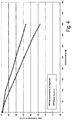
- FIG. 4 is a graph for the suction performance of a vacuum cleaner bag according to the invention shown.
- a block bottom bag made by Vorwerk Kobold FP 135 of a nonwoven material consisting of spunbond, meltblown and airlaid according to EN 60312 with DMT type 8 dust was measured for its blocking behavior. The result is shown in the bottom line. With an initially maximum volumetric flow, this decreases with increasing filling until, with a dust weight of about 400 g, a volumetric flow of less than 90 m 3 / h is present.
- a vacuum cleaner bag 1 according to the invention was also tested by the same method.
- a spunbond strip 10 made of polypropylene having a basis weight of 30 g / m 2 was additionally inserted into the vacuum cleaner bag 1, as in the FIGS. 2A and 2B is shown.
- the strip 10 had a width of 3 cm and a length of 18 cm.
- the strip 10 was welded between the two side seams in the middle of the soeinfaltung about 9 cm below the holding plate 3. The result when loading this vacuum cleaner bag 1 according to the invention with dust is shown in the upper line.
- both vacuum cleaner bags initially have the same suction power, but with an increasing filling of the vacuum cleaner bag, the suction power is less strong, so that can be maintained at a Staubeinwaage of 400 g or more than 100 m 3 / h.
Landscapes
- Engineering & Computer Science (AREA)
- Mechanical Engineering (AREA)
- Filters For Electric Vacuum Cleaners (AREA)
- Filtering Materials (AREA)
Claims (16)
- Sac d'aspirateur (1) réalisé en un voile non tissé comprenant un volume interne (8) qui est entouré de deux couches de matériau filtrant qui sont soudées sur leurs bords, une ouverture d'entrée étant formée dans le matériau filtrant, et, dans le volume interne (8) étant prévu au moins un dispositif (10) permettant de limiter la distance entre deux emplacements du matériau filtrant, situés à distance l'un de l'autre qui est relié au matériau filtrant au niveau de côtés opposés, le dispositif (10) étant plus court que le segment de matériau du matériau filtrant qui est situé entre les deux emplacements du dispositif (10) sur le matériau filtrant.
- Sac d'aspirateur (1) conforme à la revendication 1,
caractérisé en ce que
le dispositif (10) est plus court qu'une face latérale (2) du sac d'aspirateur (1), de préférence d'au moins 5%. - Sac d'aspirateur (1) conforme à la revendication 1 ou 2,
caractérisé en ce que
le dispositif (10) est réalisé sous la forme d'une bande. - Sac d'aspirateur (1) conforme à la revendication 3,
caractérisé en ce que
la bande (10) est fixée à ses extrémités opposées sur un joint de soudure de bord. - Sac d'aspirateur (1) conforme à l'une des revendications 1 à 4,
caractérisé en ce qu'
il est réalisé sous la forme d'un sac à fond foulardé. - Sac d'aspirateur (1) conforme à la revendication 5,
caractérisé en ce que
sur des côtés opposés est respectivement prévu un pli (6) dirigé vers l'intérieur et la bande (10) est reliée à ces plis (6). - Sac d'aspirateur (1) conforme à l'une des revendications 1 à 6,
caractérisé en ce qu'
il est réalisé sous la forme d'un sac plat. - Sac d'aspirateur (1) conforme à l'une des revendications 1 à 7,
caractérisé en ce que
le dispositif (10) est formé à partir d'une bande qui est rétractée thermiquement. - Sac d'aspirateur (1) conforme à l'une des revendications 1 à 8,
caractérisé en ce que
le dispositif (10) est réalisé en un matériau élastique, en particulier un voile non tissé, du caoutchouc, un film de matériau synthétique, un tissu ou un tricot. - Sac d'aspirateur (1) conforme à l'une des revendications 1 à 9,
caractérisé en ce que
le dispositif (10) comprend une bride qui peut être fixée dans une position prédéfinie. - Sac d'aspirateur (1) conforme à l'une des revendications 1 à 7,
caractérisé en ce que
le dispositif (10) est réalisé en un matériau rigide, en particulier du carton ou un matériau synthétique. - Sac d'aspirateur (1) conforme à l'une des revendications 1 à 11,
caractérisé en ce que
le dispositif (10) est collé au matériau filtrant ou soudé à celui-ci de préférence aux ultrasons. - Procédé de fabrication d'un sac d'aspirateur (1) en particulier conforme à l'une des revendications précédentes, comprenant les étapes suivantes consistant à :approvisionner une première couche d'un matériau filtrant en forme de bande,mettre en place sur la première couche, un dispositif (10) permettant de limiter la distance entre deux emplacements du matériau filtrant situés à distance l'un de l'autre qui est relié au matériau filtrant au niveau de côtés opposés,approvisionner une seconde couche d'un matériau filtrant en forme de bande,souder au niveau de leurs bords, la première et la seconde couches et achever le sac d'aspirateur (1),le dispositif (10) de limitation de la distance entre deux emplacements du matériau filtrant situés à distance l'un de l'autre étant raccourci après fixation au matériau filtrant.
- Procédé conforme à la revendication 13,
caractérisé en ce que
le dispositif (10) est réalisé en un matériau rétractable et est rétracté thermiquement après la fixation. - Procédé conforme à la revendication 13,
caractérisé en ce que
le dispositif (10) comprend une bride, et cette bride est allongée après fixation du dispositif (10) pour resserrer le matériau filtrant. - Procédé conforme à la revendication 13,
caractérisé en ce que
le dispositif (10) est réalisé en un matériau élastique qui est tendu avant sa fixation sur le matériau filtrant et se rétracte après la fixation.
Applications Claiming Priority (1)
| Application Number | Priority Date | Filing Date | Title |
|---|---|---|---|
| DE102008061250.2A DE102008061250C5 (de) | 2008-12-10 | 2008-12-10 | Staubsaugerbeutel und Verfahren zur Herstellung eines Staubsaugerbeutels |
Publications (3)
| Publication Number | Publication Date |
|---|---|
| EP2198765A2 EP2198765A2 (fr) | 2010-06-23 |
| EP2198765A3 EP2198765A3 (fr) | 2010-11-10 |
| EP2198765B1 true EP2198765B1 (fr) | 2016-06-01 |
Family
ID=40490528
Family Applications (1)
| Application Number | Title | Priority Date | Filing Date |
|---|---|---|---|
| EP09176472.0A Not-in-force EP2198765B1 (fr) | 2008-12-10 | 2009-11-19 | Sac d'aspirateur et procédé de fabrication d'un sac d'aspirateur |
Country Status (2)
| Country | Link |
|---|---|
| EP (1) | EP2198765B1 (fr) |
| DE (1) | DE102008061250C5 (fr) |
Families Citing this family (5)
| Publication number | Priority date | Publication date | Assignee | Title |
|---|---|---|---|---|
| DE102008061250C5 (de) * | 2008-12-10 | 2018-12-20 | Wolf Pvg Gmbh & Co. Kg | Staubsaugerbeutel und Verfahren zur Herstellung eines Staubsaugerbeutels |
| ES2694479T3 (es) † | 2009-06-19 | 2018-12-21 | Eurofilters N.V. | Bolsa plana para una aspiradora de polvo |
| EP2462854A1 (fr) | 2010-12-09 | 2012-06-13 | Miele & Cie. KG | Système comprenant un aspirateur et un sac d'aspirateur |
| EP2465397B1 (fr) * | 2010-12-17 | 2014-06-11 | Wolf PVG GmbH & Co. KG | Sac d'aspirateur et procédé destiné à la fabrication d'un sac d'aspirateur |
| DE102018101075A1 (de) * | 2018-01-18 | 2019-07-18 | Vorwerk & Co. Interholding Gmbh | Filter mit einem Filterinnenraum zur Aufnahme von Sauggut |
Citations (2)
| Publication number | Priority date | Publication date | Assignee | Title |
|---|---|---|---|---|
| DE3129371A1 (de) | 1981-07-25 | 1983-02-17 | Vorwerk & Co Interholding Gmbh, 5600 Wuppertal | Staubsauger-filtertuete |
| DE202008008989U1 (de) | 2008-03-07 | 2008-09-04 | Eurofilters Holding N.V. | Staubsaugerfilterbeutel |
Family Cites Families (6)
| Publication number | Priority date | Publication date | Assignee | Title |
|---|---|---|---|---|
| US2268352A (en) * | 1940-09-07 | 1941-12-30 | Hoover Co | Suction cleaner dirt bag |
| US4784676A (en) * | 1987-11-12 | 1988-11-15 | Hale Dorothy G | Disposable vacuum cleaner bag |
| US5603741A (en) * | 1994-05-09 | 1997-02-18 | Hmi Industries, Inc. | Vacuum cleaner and filter bag with air management |
| DE102005002420A1 (de) * | 2005-01-18 | 2006-07-27 | Miele & Cie. Kg | Staubsaugerbeutel und Staubsauger mit einem Staubsammelraum zur Aufnahme von Staubsaugerbeuteln |
| DE102008045683B4 (de) * | 2008-09-04 | 2012-08-16 | Branofilter Gmbh | Staubfilterbeuteleinrichtung für einen Staubsauger |
| DE102008061250C5 (de) * | 2008-12-10 | 2018-12-20 | Wolf Pvg Gmbh & Co. Kg | Staubsaugerbeutel und Verfahren zur Herstellung eines Staubsaugerbeutels |
-
2008
- 2008-12-10 DE DE102008061250.2A patent/DE102008061250C5/de not_active Expired - Fee Related
-
2009
- 2009-11-19 EP EP09176472.0A patent/EP2198765B1/fr not_active Not-in-force
Patent Citations (2)
| Publication number | Priority date | Publication date | Assignee | Title |
|---|---|---|---|---|
| DE3129371A1 (de) | 1981-07-25 | 1983-02-17 | Vorwerk & Co Interholding Gmbh, 5600 Wuppertal | Staubsauger-filtertuete |
| DE202008008989U1 (de) | 2008-03-07 | 2008-09-04 | Eurofilters Holding N.V. | Staubsaugerfilterbeutel |
Also Published As
| Publication number | Publication date |
|---|---|
| EP2198765A2 (fr) | 2010-06-23 |
| DE102008061250B4 (de) | 2013-12-12 |
| DE102008061250C5 (de) | 2018-12-20 |
| DE102008061250A1 (de) | 2009-04-30 |
| EP2198765A3 (fr) | 2010-11-10 |
Similar Documents
| Publication | Publication Date | Title |
|---|---|---|
| EP2263508B1 (fr) | Sac plat pour aspirateur avec au moins deux diffuseurs | |
| DE69020355T3 (de) | Verfahren zur befestigung eines elastischen streifens. | |
| DE2138412C3 (de) | Schwebstoff-Filterpack zur Gasreinigung aus zick-zack-förmig gefaltetem Filterpapier | |
| DE112016005342B4 (de) | Unterhosenähnliche Wegwerfwindel | |
| EP2098153A1 (fr) | Sac d'aspirateur | |
| DE202008008989U1 (de) | Staubsaugerfilterbeutel | |
| DE10203460A1 (de) | In einen Staubsauger einsetzbare Filtereinrichtung | |
| EP1525041A1 (fr) | Element de filtrage et procede de fabrication | |
| EP3386363B1 (fr) | Procede de liaison interposee d'une plaque de support et d'une paroi d'un sac d'aspirateur et sac d'aspirateur | |
| DE202008016300U1 (de) | Staubsaugerbeutel | |
| DE102008061250B4 (de) | Staubsaugerbeutel und Verfahren zur Herstellung eines Staubsaugerbeutels | |
| DE102008006769A1 (de) | Verfahren zur Herstellung eines Staubfilterbeutels mit Seitenfalten und Staubfilterbeutel | |
| EP3142537B1 (fr) | Sac filtrant d'aspirateur doté d'un cordon de soudure très résistant, son procédé de fabrication, outillage et installation de soudage par ultrasons destinée à la fabrication d'un cordon de soudure extrêmement résistant | |
| DE102008045683A1 (de) | Staubfilterbeuteleinrichtung für einen Staubsauger | |
| DE102008016596B4 (de) | Staubfilterbeutel für Staubsauger | |
| EP2266450B1 (fr) | Filtre sac à fond plat pour aspirateurs | |
| WO2010000453A1 (fr) | Sac filtrant constitué d'un sac extérieur et d'un sac intérieur et utilisable dans un aspirateur | |
| DE202009004433U1 (de) | Blockbodenbeutel mit zusätzlicher Schweißnaht und Sollfaltlinien | |
| DE102008031988B3 (de) | Filterbeutel mit äußerem und innerem Beutel zum Einsatz in einem Staubsauger | |
| EP2465397B1 (fr) | Sac d'aspirateur et procédé destiné à la fabrication d'un sac d'aspirateur | |
| DE102004054245A1 (de) | Filterelement und Filter | |
| EP2979742A1 (fr) | Fixation de matériau filtrant | |
| DE69725890T2 (de) | Windel mit falten zur eindämmung von flüssigen und festen abfallstoffen | |
| DE102013102927A1 (de) | Schutzkittel und Verfahren zur Herstellung eines elastischen Bereichs an einem Schutzkittel | |
| DE102008031989A1 (de) | Staubfilterbeutel mit geschlitztem Material zum Einsatz in einem Staubsauger |
Legal Events
| Date | Code | Title | Description |
|---|---|---|---|
| PUAI | Public reference made under article 153(3) epc to a published international application that has entered the european phase |
Free format text: ORIGINAL CODE: 0009012 |
|
| AK | Designated contracting states |
Kind code of ref document: A2 Designated state(s): AT BE BG CH CY CZ DE DK EE ES FI FR GB GR HR HU IE IS IT LI LT LU LV MC MK MT NL NO PL PT RO SE SI SK SM TR |
|
| PUAL | Search report despatched |
Free format text: ORIGINAL CODE: 0009013 |
|
| AK | Designated contracting states |
Kind code of ref document: A3 Designated state(s): AT BE BG CH CY CZ DE DK EE ES FI FR GB GR HR HU IE IS IT LI LT LU LV MC MK MT NL NO PL PT RO SE SI SK SM TR |
|
| 17P | Request for examination filed |
Effective date: 20110309 |
|
| 17Q | First examination report despatched |
Effective date: 20150929 |
|
| GRAP | Despatch of communication of intention to grant a patent |
Free format text: ORIGINAL CODE: EPIDOSNIGR1 |
|
| INTG | Intention to grant announced |
Effective date: 20160301 |
|
| RIN1 | Information on inventor provided before grant (corrected) |
Inventor name: CZADO, WOLFGANG |
|
| GRAS | Grant fee paid |
Free format text: ORIGINAL CODE: EPIDOSNIGR3 |
|
| GRAA | (expected) grant |
Free format text: ORIGINAL CODE: 0009210 |
|
| AK | Designated contracting states |
Kind code of ref document: B1 Designated state(s): AT BE BG CH CY CZ DE DK EE ES FI FR GB GR HR HU IE IS IT LI LT LU LV MC MK MT NL NO PL PT RO SE SI SK SM TR |
|
| REG | Reference to a national code |
Ref country code: GB Ref legal event code: FG4D Free format text: NOT ENGLISH |
|
| REG | Reference to a national code |
Ref country code: CH Ref legal event code: EP Ref country code: AT Ref legal event code: REF Ref document number: 803328 Country of ref document: AT Kind code of ref document: T Effective date: 20160615 |
|
| REG | Reference to a national code |
Ref country code: IE Ref legal event code: FG4D Free format text: LANGUAGE OF EP DOCUMENT: GERMAN |
|
| REG | Reference to a national code |
Ref country code: DE Ref legal event code: R096 Ref document number: 502009012646 Country of ref document: DE |
|
| REG | Reference to a national code |
Ref country code: LT Ref legal event code: MG4D |
|
| REG | Reference to a national code |
Ref country code: NL Ref legal event code: MP Effective date: 20160601 |
|
| PG25 | Lapsed in a contracting state [announced via postgrant information from national office to epo] |
Ref country code: FI Free format text: LAPSE BECAUSE OF FAILURE TO SUBMIT A TRANSLATION OF THE DESCRIPTION OR TO PAY THE FEE WITHIN THE PRESCRIBED TIME-LIMIT Effective date: 20160601 Ref country code: LT Free format text: LAPSE BECAUSE OF FAILURE TO SUBMIT A TRANSLATION OF THE DESCRIPTION OR TO PAY THE FEE WITHIN THE PRESCRIBED TIME-LIMIT Effective date: 20160601 Ref country code: NO Free format text: LAPSE BECAUSE OF FAILURE TO SUBMIT A TRANSLATION OF THE DESCRIPTION OR TO PAY THE FEE WITHIN THE PRESCRIBED TIME-LIMIT Effective date: 20160901 |
|
| PG25 | Lapsed in a contracting state [announced via postgrant information from national office to epo] |
Ref country code: SE Free format text: LAPSE BECAUSE OF FAILURE TO SUBMIT A TRANSLATION OF THE DESCRIPTION OR TO PAY THE FEE WITHIN THE PRESCRIBED TIME-LIMIT Effective date: 20160601 Ref country code: ES Free format text: LAPSE BECAUSE OF FAILURE TO SUBMIT A TRANSLATION OF THE DESCRIPTION OR TO PAY THE FEE WITHIN THE PRESCRIBED TIME-LIMIT Effective date: 20160601 Ref country code: LV Free format text: LAPSE BECAUSE OF FAILURE TO SUBMIT A TRANSLATION OF THE DESCRIPTION OR TO PAY THE FEE WITHIN THE PRESCRIBED TIME-LIMIT Effective date: 20160601 Ref country code: HR Free format text: LAPSE BECAUSE OF FAILURE TO SUBMIT A TRANSLATION OF THE DESCRIPTION OR TO PAY THE FEE WITHIN THE PRESCRIBED TIME-LIMIT Effective date: 20160601 Ref country code: GR Free format text: LAPSE BECAUSE OF FAILURE TO SUBMIT A TRANSLATION OF THE DESCRIPTION OR TO PAY THE FEE WITHIN THE PRESCRIBED TIME-LIMIT Effective date: 20160902 Ref country code: NL Free format text: LAPSE BECAUSE OF FAILURE TO SUBMIT A TRANSLATION OF THE DESCRIPTION OR TO PAY THE FEE WITHIN THE PRESCRIBED TIME-LIMIT Effective date: 20160601 |
|
| REG | Reference to a national code |
Ref country code: DE Ref legal event code: R026 Ref document number: 502009012646 Country of ref document: DE |
|
| PLBI | Opposition filed |
Free format text: ORIGINAL CODE: 0009260 |
|
| 26 | Opposition filed |
Opponent name: EUROFILTERS HOLDING N.V. Effective date: 20161212 |
|
| PG25 | Lapsed in a contracting state [announced via postgrant information from national office to epo] |
Ref country code: IS Free format text: LAPSE BECAUSE OF FAILURE TO SUBMIT A TRANSLATION OF THE DESCRIPTION OR TO PAY THE FEE WITHIN THE PRESCRIBED TIME-LIMIT Effective date: 20161001 Ref country code: RO Free format text: LAPSE BECAUSE OF FAILURE TO SUBMIT A TRANSLATION OF THE DESCRIPTION OR TO PAY THE FEE WITHIN THE PRESCRIBED TIME-LIMIT Effective date: 20160601 Ref country code: CZ Free format text: LAPSE BECAUSE OF FAILURE TO SUBMIT A TRANSLATION OF THE DESCRIPTION OR TO PAY THE FEE WITHIN THE PRESCRIBED TIME-LIMIT Effective date: 20160601 Ref country code: EE Free format text: LAPSE BECAUSE OF FAILURE TO SUBMIT A TRANSLATION OF THE DESCRIPTION OR TO PAY THE FEE WITHIN THE PRESCRIBED TIME-LIMIT Effective date: 20160601 Ref country code: SK Free format text: LAPSE BECAUSE OF FAILURE TO SUBMIT A TRANSLATION OF THE DESCRIPTION OR TO PAY THE FEE WITHIN THE PRESCRIBED TIME-LIMIT Effective date: 20160601 Ref country code: IT Free format text: LAPSE BECAUSE OF FAILURE TO SUBMIT A TRANSLATION OF THE DESCRIPTION OR TO PAY THE FEE WITHIN THE PRESCRIBED TIME-LIMIT Effective date: 20160601 |
|
| PG25 | Lapsed in a contracting state [announced via postgrant information from national office to epo] |
Ref country code: PT Free format text: LAPSE BECAUSE OF FAILURE TO SUBMIT A TRANSLATION OF THE DESCRIPTION OR TO PAY THE FEE WITHIN THE PRESCRIBED TIME-LIMIT Effective date: 20161003 Ref country code: SM Free format text: LAPSE BECAUSE OF FAILURE TO SUBMIT A TRANSLATION OF THE DESCRIPTION OR TO PAY THE FEE WITHIN THE PRESCRIBED TIME-LIMIT Effective date: 20160601 Ref country code: BE Free format text: LAPSE BECAUSE OF NON-PAYMENT OF DUE FEES Effective date: 20161130 Ref country code: PL Free format text: LAPSE BECAUSE OF FAILURE TO SUBMIT A TRANSLATION OF THE DESCRIPTION OR TO PAY THE FEE WITHIN THE PRESCRIBED TIME-LIMIT Effective date: 20160601 |
|
| PLAX | Notice of opposition and request to file observation + time limit sent |
Free format text: ORIGINAL CODE: EPIDOSNOBS2 |
|
| PG25 | Lapsed in a contracting state [announced via postgrant information from national office to epo] |
Ref country code: DK Free format text: LAPSE BECAUSE OF FAILURE TO SUBMIT A TRANSLATION OF THE DESCRIPTION OR TO PAY THE FEE WITHIN THE PRESCRIBED TIME-LIMIT Effective date: 20160601 Ref country code: SI Free format text: LAPSE BECAUSE OF FAILURE TO SUBMIT A TRANSLATION OF THE DESCRIPTION OR TO PAY THE FEE WITHIN THE PRESCRIBED TIME-LIMIT Effective date: 20160601 |
|
| REG | Reference to a national code |
Ref country code: CH Ref legal event code: PL |
|
| PLBB | Reply of patent proprietor to notice(s) of opposition received |
Free format text: ORIGINAL CODE: EPIDOSNOBS3 |
|
| GBPC | Gb: european patent ceased through non-payment of renewal fee |
Effective date: 20161119 |
|
| PG25 | Lapsed in a contracting state [announced via postgrant information from national office to epo] |
Ref country code: LI Free format text: LAPSE BECAUSE OF NON-PAYMENT OF DUE FEES Effective date: 20161130 Ref country code: CH Free format text: LAPSE BECAUSE OF NON-PAYMENT OF DUE FEES Effective date: 20161130 |
|
| REG | Reference to a national code |
Ref country code: IE Ref legal event code: MM4A |
|
| REG | Reference to a national code |
Ref country code: FR Ref legal event code: ST Effective date: 20170731 |
|
| PG25 | Lapsed in a contracting state [announced via postgrant information from national office to epo] |
Ref country code: LU Free format text: LAPSE BECAUSE OF NON-PAYMENT OF DUE FEES Effective date: 20161130 |
|
| PG25 | Lapsed in a contracting state [announced via postgrant information from national office to epo] |
Ref country code: FR Free format text: LAPSE BECAUSE OF NON-PAYMENT OF DUE FEES Effective date: 20161130 |
|
| PG25 | Lapsed in a contracting state [announced via postgrant information from national office to epo] |
Ref country code: GB Free format text: LAPSE BECAUSE OF NON-PAYMENT OF DUE FEES Effective date: 20161119 Ref country code: IE Free format text: LAPSE BECAUSE OF NON-PAYMENT OF DUE FEES Effective date: 20161119 |
|
| REG | Reference to a national code |
Ref country code: AT Ref legal event code: MM01 Ref document number: 803328 Country of ref document: AT Kind code of ref document: T Effective date: 20161119 |
|
| PG25 | Lapsed in a contracting state [announced via postgrant information from national office to epo] |
Ref country code: AT Free format text: LAPSE BECAUSE OF NON-PAYMENT OF DUE FEES Effective date: 20161119 |
|
| REG | Reference to a national code |
Ref country code: BE Ref legal event code: MM Effective date: 20161130 |
|
| PG25 | Lapsed in a contracting state [announced via postgrant information from national office to epo] |
Ref country code: HU Free format text: LAPSE BECAUSE OF FAILURE TO SUBMIT A TRANSLATION OF THE DESCRIPTION OR TO PAY THE FEE WITHIN THE PRESCRIBED TIME-LIMIT; INVALID AB INITIO Effective date: 20091119 Ref country code: CY Free format text: LAPSE BECAUSE OF FAILURE TO SUBMIT A TRANSLATION OF THE DESCRIPTION OR TO PAY THE FEE WITHIN THE PRESCRIBED TIME-LIMIT Effective date: 20160601 |
|
| PG25 | Lapsed in a contracting state [announced via postgrant information from national office to epo] |
Ref country code: MK Free format text: LAPSE BECAUSE OF FAILURE TO SUBMIT A TRANSLATION OF THE DESCRIPTION OR TO PAY THE FEE WITHIN THE PRESCRIBED TIME-LIMIT Effective date: 20160601 Ref country code: TR Free format text: LAPSE BECAUSE OF FAILURE TO SUBMIT A TRANSLATION OF THE DESCRIPTION OR TO PAY THE FEE WITHIN THE PRESCRIBED TIME-LIMIT Effective date: 20160601 Ref country code: MC Free format text: LAPSE BECAUSE OF FAILURE TO SUBMIT A TRANSLATION OF THE DESCRIPTION OR TO PAY THE FEE WITHIN THE PRESCRIBED TIME-LIMIT Effective date: 20160601 |
|
| PG25 | Lapsed in a contracting state [announced via postgrant information from national office to epo] |
Ref country code: BG Free format text: LAPSE BECAUSE OF FAILURE TO SUBMIT A TRANSLATION OF THE DESCRIPTION OR TO PAY THE FEE WITHIN THE PRESCRIBED TIME-LIMIT Effective date: 20160601 |
|
| PG25 | Lapsed in a contracting state [announced via postgrant information from national office to epo] |
Ref country code: MT Free format text: LAPSE BECAUSE OF FAILURE TO SUBMIT A TRANSLATION OF THE DESCRIPTION OR TO PAY THE FEE WITHIN THE PRESCRIBED TIME-LIMIT Effective date: 20160601 |
|
| PLCK | Communication despatched that opposition was rejected |
Free format text: ORIGINAL CODE: EPIDOSNREJ1 |
|
| STAA | Information on the status of an ep patent application or granted ep patent |
Free format text: STATUS: THE PATENT HAS BEEN GRANTED |
|
| APAH | Appeal reference modified |
Free format text: ORIGINAL CODE: EPIDOSCREFNO |
|
| APBM | Appeal reference recorded |
Free format text: ORIGINAL CODE: EPIDOSNREFNO |
|
| APBP | Date of receipt of notice of appeal recorded |
Free format text: ORIGINAL CODE: EPIDOSNNOA2O |
|
| APBQ | Date of receipt of statement of grounds of appeal recorded |
Free format text: ORIGINAL CODE: EPIDOSNNOA3O |
|
| REG | Reference to a national code |
Ref country code: DE Ref legal event code: R100 Ref document number: 502009012646 Country of ref document: DE |
|
| APBU | Appeal procedure closed |
Free format text: ORIGINAL CODE: EPIDOSNNOA9O |
|
| PGFP | Annual fee paid to national office [announced via postgrant information from national office to epo] |
Ref country code: DE Payment date: 20220322 Year of fee payment: 13 |
|
| PLBN | Opposition rejected |
Free format text: ORIGINAL CODE: 0009273 |
|
| STAA | Information on the status of an ep patent application or granted ep patent |
Free format text: STATUS: OPPOSITION REJECTED |
|
| 27O | Opposition rejected |
Effective date: 20220322 |
|
| REG | Reference to a national code |
Ref country code: DE Ref legal event code: R119 Ref document number: 502009012646 Country of ref document: DE |
|
| PG25 | Lapsed in a contracting state [announced via postgrant information from national office to epo] |
Ref country code: DE Free format text: LAPSE BECAUSE OF NON-PAYMENT OF DUE FEES Effective date: 20230601 |