EP2465397B1 - Sac d'aspirateur et procédé destiné à la fabrication d'un sac d'aspirateur - Google Patents
Sac d'aspirateur et procédé destiné à la fabrication d'un sac d'aspirateur Download PDFInfo
- Publication number
- EP2465397B1 EP2465397B1 EP20100195704 EP10195704A EP2465397B1 EP 2465397 B1 EP2465397 B1 EP 2465397B1 EP 20100195704 EP20100195704 EP 20100195704 EP 10195704 A EP10195704 A EP 10195704A EP 2465397 B1 EP2465397 B1 EP 2465397B1
- Authority
- EP
- European Patent Office
- Prior art keywords
- vacuum cleaner
- holding means
- cleaner bag
- inwardly folded
- bag according
- Prior art date
- Legal status (The legal status is an assumption and is not a legal conclusion. Google has not performed a legal analysis and makes no representation as to the accuracy of the status listed.)
- Not-in-force
Links
Images



Classifications
-
- A—HUMAN NECESSITIES
- A47—FURNITURE; DOMESTIC ARTICLES OR APPLIANCES; COFFEE MILLS; SPICE MILLS; SUCTION CLEANERS IN GENERAL
- A47L—DOMESTIC WASHING OR CLEANING; SUCTION CLEANERS IN GENERAL
- A47L9/00—Details or accessories of suction cleaners, e.g. mechanical means for controlling the suction or for effecting pulsating action; Storing devices specially adapted to suction cleaners or parts thereof; Carrying-vehicles specially adapted for suction cleaners
- A47L9/10—Filters; Dust separators; Dust removal; Automatic exchange of filters
- A47L9/14—Bags or the like; Rigid filtering receptacles; Attachment of, or closures for, bags or receptacles
Definitions
- the present invention relates to a vacuum cleaner bag having at least one inwardly folded wall portion which is held in at least one holding means in the inwardly folded position.
- the DE 20 2008 016 300 discloses a vacuum cleaner bag in which an inwardly directed fold is arranged on one side. In operation, this fold may inflate outwardly, thus significantly increasing the internal volume of the vacuum cleaner bag.
- a disadvantage of such inwardly folded wall sections that they inflate during operation and press outwards, so that the filter material presses against the inner wall of the dust chamber of the vacuum cleaner and in large areas, a flow of air is difficult to be prevented. This deteriorates the suction power. If the inwardly folded wall section remains folded in, the suction performance is likewise impaired since the filter material is not or only insignificantly flows through in the region of the fold.
- the EP 2 198 765 discloses a vacuum cleaner bag in the form of a block bottom bag, in which a spacer is provided in an interior, which limits the distance between two side walls to each other, to avoid uncontrolled inflation of the vacuum cleaner bag.
- the inwardly folded wall section is held in the inwardly folded position via at least one retaining means.
- the inwardly folded wall portion is available as a filter surface and thus the filter area in relation to the internal volume of the vacuum cleaner bag is significantly higher than without inwardly folded wall portion.
- the holding means has at least one recess or is formed from a net or grid. This ensures that the holding agent can be flowed through and does not adversely affect the suction power.
- the recess in the holding means is preferably arranged laterally offset from an inflow opening in the upper part or the lower part, so that the holding means also acts as an impact protection and deflects an incoming air flow.
- the size of the recess is preferably greater than 2 cm 2 , in particular larger than the inflow opening.
- the geometry of the recess is freely selectable and also several recesses may be incorporated into the retaining means.
- the holding means is fixed at least in a central region of the wall portion.
- the inwardly folded wall portion may be fixed over the entire length by the holding means, but for the function of holding the inwardly folded portion to prevent inflation, however, it suffices if the inwardly folded wall portion at one or more points on the Hattestoff is fixed.
- a fixation on the holding means is particularly useful in the central region, since the inwardly folded wall portion is preferably also fixed to a seam of the vacuum cleaner bag edge.
- the vacuum cleaner bag on at least two sides on an inwardly folded wall portion.
- the two inwardly folded wall portions may be connected to each other via the holding means, so that in operation the holding means is loaded to train through the wall sections.
- the inwardly folded wall portions may be formed symmetrically in order to avoid a displacement of the holding means to a direction by unilaterally acting tensile forces.
- the holding means is preferably connected via a seam with the inwardly folded wall portion.
- the seam is preferably directed outwards, so that the seam does not restrict the effective filter volume of the vacuum cleaner bag.
- the vacuum cleaner bag preferably comprises a top and a bottom as a sheet.
- the holding means may be formed as an air-permeable sheet.
- the materials used are preferably single-layer or multi-layer nonwoven materials, paper, composite materials, films or other materials.
- fabrics such as meshes, scrims, yarn, paper, cardboard or foil. To form a seam, these materials can preferably be welded or glued.
- At least one seam is provided, which connects the upper part, the lower part and the holding means with each other.
- the holding means is formed integrally with the upper part and / or the lower part. It is possible to manufacture upper part, lower part and holding means separately, but also an integral design of the holding means is possible.
- the holding means may be formed in one or two layers, wherein it is possible in a two-ply training to connect an upper layer to the upper part and a lower layer with the lower part, so that the retaining means with the two layers edge forms the inwardly folded wall portion ,
- the holding means is held by at least one holder on the upper part and / or lower part.
- a predetermined distance of the holding means to the upper part and / or lower part can be specified, in particular it can be prevented that the holding means rests on the upper part or lower part and thus the available filter surface is reduced.
- the at least one holder is formed integrally with the holding means, for example as a material strip, which is then fixed to the upper part or lower part.
- the strip of material can be provided by punching out the passage opening if the material strip remains at least partially connected to the holding means during punching.
- an upper part and a lower part are first provided from a sheet of air-permeable material, the upper part and lower part are preferably formed separately, but can also be made integrally from one piece.
- a holding means is arranged on a marginal first edge of the upper part and a first edge or fold of the lower part. Then, the first edge of the upper part is connected to the holding means and a first edge or fold of the lower part.
- a second edge or fold of the upper part is then connected to the holding means and a second edge or fold of the lower part, which connects the holding means to the lower part.
- upper part and lower part of sheet material are substantially tubular and promoted to form a vacuum cleaner bag then upper part and lower part perpendicular to the conveying direction and connected to each other, preferably welded.
- the production of the vacuum cleaner bag can be done in a continuous flow process with high efficiency.
- upper part, lower part and retaining means of weldable materials such as a single or multi-layer nonwoven fabric, which are then welded together.
- one, two or three webs of a filter material can be supplied to a processing station.
- a vacuum cleaner bag 1 comprises an upper part and a lower part 3 made of an air-permeable material, in particular a nonwoven fabric, paper, film or composite material.
- the vacuum cleaner bag 1 has on two opposite sides of an inwardly folded wall portion 4 on.
- Each inwardly folded wall portion 4 comprises an upper pleat leg 5, which is formed integrally with the upper part 2, and a lower pleat leg 6, which is formed integrally with the lower part 3.
- a holding means 8 is arranged in the form of a sheet, which is at least partially connected to the inwardly folded wall portion 4.
- the holding means 8 is formed from a sheet of air-permeable material, in particular a nonwoven fabric, paper, foil, a scrim, mesh or other material. A training as a strip, yarn or other connection means between the opposite wall sections 4 is possible.
- the holding means 8 can be loaded in tension and can also have a certain elasticity.
- the holding means 8 prevents that the two inwardly folded wall sections 4 inflate during operation of the vacuum cleaner bag to the outside.
- the holding means 8 can be fixed only in a central region on the inwardly folded wall portion 4. It is also possible that the holding means 8 is fixed over the entire length of the folding edge 7.
- the holding means 8 is intended to prevent at least a swelling of the inwardly folded wall portion 4 to the outside.
- a seam 9 is provided, which is formed by welding or gluing, and on the pleat legs 5 of the upper part 2, the pleat legs 6 of the lower part 3 and an edge portion of the holding means are fixed to each other, preferably by welding or gluing.
- a seam 10 is provided, which also connects the pleat leg 5 and the pleat leg 6 and the retaining means 8. The seams 9 and 10 are each directed outwards and thus are outside the internal volume of the vacuum cleaner bag.
- FIG. 2 the items of the vacuum cleaner bag 1 are shown before the assembly.
- an inflow opening 12 is recessed, which is surrounded by a holding plate 11.
- a recess 13 is provided, which is formed larger than the inflow opening 12 and after the preparation of the vacuum cleaner bag 1 of the inflow opening 12 is opposite. It is also possible for the recess 13 to be arranged offset to the inflow opening 12, so that an incoming air flow is at least partially deflected by the holding means 8, so that the holding means 8 acts as impact protection.
- the upper part 2, the lower part 3 and the holding means 8 are each shown as a rectangular sheet, wherein it is expedient for the production when upper part 2, lower part 3 and holding means 8 are fed as web material to a processing station.
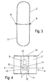
- FIG. 3 an intermediate stage of the production of the vacuum cleaner bag 1 is shown.
- the upper part 2 and the lower part 3 are formed substantially tubular and are separated on the mutually facing side by the holding means 8 from each other. In the region of the free edges of the upper part 2 and the lower part 3 and the edges of the holding means 8, these have been connected to seams 9 and 10 with each other.
- the intermediate stage of the vacuum cleaner bag 1 has an upper hose and a lower hose, which are separated from one another via the holding means 8. In the holding means 8 only recesses 13 are introduced, which allow a flow through.
- the now flat superimposed track section is formed on four opposite sides of four layers, while in the central region, only the upper part 2, the holding means 8 and the lower part 3 are present.
- This web is now guided to a cutting and welding station, cut perpendicular to the conveying direction of the vacuum cleaner bag 1 and welded.
- the finished vacuum cleaner bag is in the plan view in FIG. 4 shown.
- the inwardly folded wall sections 4 are arranged with a folding edge 7.
- the wall sections 4 have a width which is between 10% and 40% of the width of the vacuum cleaner bag, preferably in a range between 1 cm and 8 cm, in particular 2 cm to 5 cm.
- cutting edges 14 are provided, which are arranged adjacent to a seam 15, for example by welding or gluing.
- the recess 13 is laterally offset from the inflow opening 12. It is of course also possible to arrange the recess 13 in alignment with the inflow opening 12.
- a plurality of recesses 13 may be provided, for example, on both sides of the inflow opening 12 at least one recess 13th be provided.
- the holding means 8 may also consist of a net or scrim, so that the introduction of recesses 13 is not necessary.
- FIG. 5 a modified embodiment for a vacuum cleaner bag 1 is shown, which corresponds in shape substantially to the previous embodiment. Only the holding means 8 'is formed integrally with the lower part 3, so that instead of the three individual parts ( FIG. 2 ) only two items are available.
- the upper part 2 corresponds to the previous embodiment.
- a seam 9 is now produced on one side, in which an edge of the upper part 2 with an edge of the holding means 8 'and an edge of the lower part 3 are interconnected.
- a modified seam 10 ' On the opposite side is a modified seam 10 ', in which an edge of the upper part 2 is connected to a fold, a strip or a transition region 10' between the holding means 8 'and the lower part 3. In this respect, only one edge and one fold or strip are connected to each other.
- the vacuum cleaner bag 1 from a single web, so that upper part 2, holding means 8 'and lower part 3 are formed integrally. Then, at the seams 9 and 10, only one edge of the upper part 2 or of the lower part 3 is fixed to one another with a transition section 10 'between holding means and lower part 3 or holding means and upper part 2.
- vacuum bags 1 extend the seams 9 and 10 over the entire length of the vacuum cleaner bag 1. It is of course possible to provide the fixation of the holding means 8 only in a central region, so shorter form.
- the inwardly folded wall sections 4 could also be held together only in a central region, while in the peripheral region, the seams 15 prevent outward swelling.
- the holding means 8 need not extend over the entire length of the vacuum cleaner bag 1. It is possible to form the retaining means 8 only as a transverse strip, which is arranged in the region of the inflow opening 12 and is connected at opposite end faces with the inwardly folded wall sections 4.
- FIG. 6 shows a perspective view of another embodiment of a vacuum cleaner bag, in which compared to the in FIG. 1 embodiment shown still a holder 20 is provided and otherwise the same components are denoted by the same reference numerals.
- the holder 20 is formed by a strip of material which is formed during the punching of the passage opening 13 when at least a part of the material strip remains connected to the holding means 8, as shown at an edge 22.
- the holder 20 is fixed at the free end to the upper part 2 adjacent to the inflow opening 12, so that an incoming air flow initially strikes the holder 20, which acts as a deflection device and impact protection.
- the holder 20 also ensures that the holding means 8 does not rest on the lower part 3 but spaced from the lower part 3 is held.
- FIG. 7 is one opposite FIG. 6 modified embodiment shown in which a holder 30 is formed integrally with a holding means 8.
- the holder 30 is connected at a transition to the holding means 8 and fixed on the opposite side 32 on the lower part 3 in a central region opposite to the inflow opening 12.
- the holder 30 can also form an impact protection and also ensures that the incoming air flow pulls the lower part 3 away from the upper part 2 and the retaining means 8 is also pulled away from the upper part 2 by the holder 30. This ensures that the holding means 8 is spaced from the upper part 2 and held by the lower part 3 and the corresponding filter surfaces can be flowed through.
- a holder 40 is provided, which is arranged in a loop shape and unlike the holder 20 in FIG. 6 is fixed at the free end 41 on the opposite side of the inflow opening 12.
- an air flow entering through the inflow opening 12 can flow through the through-opening 13 onto the lower part 3, then being pulled away from the holding means 8 and the upper part 2, so that a secure unfolding of the vacuum cleaner bag after insertion into a vacuum cleaner is ensured.
- FIGS. 6 to 8 shown holders 20, 30 and 40 may be combined with each other, for example, a plurality of holders may be fixed to the holding means 8 in order to ensure a predetermined spacing between the upper part 2, holding means 8 and lower part 3.
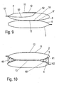
- FIG. 9 a vacuum cleaner bag is shown in which a dividing wall 50 is arranged in an upper chamber between upper part 2 and a holding means 8 "', the dividing wall 50 being adjacent to an edge 52 Inflow opening 12 fixed to the upper part 2 and on the opposite side to a seam 51 between the upper part 2 and a pleat leg 5.
- the partition may be formed as a rectangular piece of material, preferably made of a non-woven, and at the edges, not shown, at the seams 15 of the vacuum cleaner bag ( FIG. 4 ).
- the holding means 8 is formed in two layers, with an upper layer forming the upper pleat leg 5 and a lower layer forming the lower pleat leg 6.
- the pleat legs 5 and 6 are connected to one another at at least one connection point 18, preferably a weld includes a frame-shaped portion surrounding a through-hole 13.
- the partition 50 omitted and arranged on opposite sides an additional spacer 60 between the upper pleat leg 5 and the lower pleat leg 6.
- the spacer 60 is formed from a shaped body, for example made of foam, and has upper ribs 61 for abutment with the upper fold leg 5 and lower ribs 62 for engagement with the lower fold leg 6.
- partition 50 and the spacer 60 can also in the embodiments of FIGS. 1 to 8 be provided.
Landscapes
- Engineering & Computer Science (AREA)
- Mechanical Engineering (AREA)
- Filters For Electric Vacuum Cleaners (AREA)
Claims (12)
- Sac d'aspirateur (1) comportant au moins un segment de paroi (4) replié vers l'intérieur qui est maintenu dans la position repliée vers l'intérieur par au moins un moyen de retenue (8, 8'),
caractérisé en ce que
le moyen de retenue (8, 8') est formé par un élément surfacique perméable à l'air qui comporte au moins un évidement (13) où est formé par un réseau ou treillis. - Sac d'aspirateur conforme à la revendication 1,
caractérisé en ce que
le moyen de retenue (8, 8') est fixé au moins dans une zone médiane du segment de paroi (4) replié vers l'intérieur. - Sac d'aspirateur conforme à la revendication 1 ou 2,
caractérisé en ce qu'
il est prévu un segment de paroi replié vers l'intérieur (4) sur au moins deux côtés. - Sac d'aspirateur conforme à l'une des revendications précédentes,
caractérisé en ce que
deux segments de paroi (4) repliés vers l'intérieur sont reliés entre eux par le moyen de retenue (8, 8'). - Sac d'aspirateur conforme à l'une des revendications précédentes,
caractérisé en ce que
les moyens de retenue (8, 8') sont reliés au segment de paroi (4) replié vers l'intérieur par une jointure (9, 10). - Sac d'aspirateur conforme à la revendication 5,
caractérisé en ce que
la jointure (9, 10) est orientée vers l'extérieur. - Sac d'aspirateur conforme à l'une des revendications précédentes,
caractérisé en ce que
le sac d'aspirateur (1) comporte une partie supérieure (2) et une partie inférieure (3) réalisées sous la forme d'éléments surfaciques. - Sac d'aspirateur conforme à la revendication 7,
caractérisé en ce qu'
il est prévu au moins une jointure (9, 10) qui relie la partie supérieure (2), la partie inférieure (3) et le moyen de retenue (8, 8'). - Sac d'aspirateur conforme à l'une des revendications 1 à 8,
caractérisé en ce que
l'évidement (13) est décalé latéralement par rapport à une ouverture d'entrée (12) située dans la partie supérieure (2) ou dans la partie inférieure (3). - Sac d'aspirateur conforme à l'une des revendications précédentes,
caractérisé en ce que
le moyen de retenue (8') est réalisé intégralement avec la partie supérieure (2) et/ou la partie inférieure (3). - Sac d'aspirateur conforme à l'une des revendications précédentes,
caractérisé en ce qu'
il est réalisé sous la forme d'un sac plat, et comporte sur ses côtés opposés un segment de bord quadri couches avec un segment de paroi (4) replié vers l'intérieur. - Sac d'aspirateur conforme à l'une des revendications précédentes,
caractérisé en ce que
le moyen de retenue (8, 8') est maintenu sur la partie supérieure (2) et/ou sur la partie inférieure (3) par au moins un élément de fixation (20, 30, 40).
Priority Applications (1)
| Application Number | Priority Date | Filing Date | Title |
|---|---|---|---|
| EP20100195704 EP2465397B1 (fr) | 2010-12-17 | 2010-12-17 | Sac d'aspirateur et procédé destiné à la fabrication d'un sac d'aspirateur |
Applications Claiming Priority (1)
| Application Number | Priority Date | Filing Date | Title |
|---|---|---|---|
| EP20100195704 EP2465397B1 (fr) | 2010-12-17 | 2010-12-17 | Sac d'aspirateur et procédé destiné à la fabrication d'un sac d'aspirateur |
Publications (2)
| Publication Number | Publication Date |
|---|---|
| EP2465397A1 EP2465397A1 (fr) | 2012-06-20 |
| EP2465397B1 true EP2465397B1 (fr) | 2014-06-11 |
Family
ID=44025252
Family Applications (1)
| Application Number | Title | Priority Date | Filing Date |
|---|---|---|---|
| EP20100195704 Not-in-force EP2465397B1 (fr) | 2010-12-17 | 2010-12-17 | Sac d'aspirateur et procédé destiné à la fabrication d'un sac d'aspirateur |
Country Status (1)
| Country | Link |
|---|---|
| EP (1) | EP2465397B1 (fr) |
Families Citing this family (3)
| Publication number | Priority date | Publication date | Assignee | Title |
|---|---|---|---|---|
| DE102012219341A1 (de) * | 2012-10-23 | 2014-04-24 | BSH Bosch und Siemens Hausgeräte GmbH | Staubfilterbeutel für einen Staubsauger |
| DE102015114330A1 (de) * | 2015-08-28 | 2017-03-02 | Branofilter Gmbh | Staubfilterbeutel |
| ES2916748T3 (es) † | 2015-12-12 | 2022-07-05 | Procedimiento para producir una unión por material entre una placa de retención y la pared de una bolsa de filtro de aspiradora, así como bolsa de filtro de aspiradora |
Family Cites Families (10)
| Publication number | Priority date | Publication date | Assignee | Title |
|---|---|---|---|---|
| DE129156C (fr) * | ||||
| US2014118A (en) * | 1933-11-27 | 1935-09-10 | Hoover Co | Suction cleaner |
| US2268352A (en) * | 1940-09-07 | 1941-12-30 | Hoover Co | Suction cleaner dirt bag |
| GB694415A (en) * | 1951-03-02 | 1953-07-22 | British Thomson Houston Co Ltd | Improvements in and relating to vacuum cleaner dust bags |
| US2620045A (en) * | 1951-09-06 | 1952-12-02 | Hoover Co | Suction cleaner bag |
| BE528940A (fr) * | 1953-05-18 | |||
| CA1007578A (en) * | 1973-09-17 | 1977-03-29 | Edward G. Lutz | Filter bag structure for a suction cleaner |
| DE8815619U1 (de) * | 1988-12-16 | 1989-01-26 | Branofilter Gmbh, 8501 Dietenhofen | Vorrichtung für Industrie-Staubabsauggeräte zur Aufnahme des abgesaugten Staubes |
| DE102008061250C5 (de) * | 2008-12-10 | 2018-12-20 | Wolf Pvg Gmbh & Co. Kg | Staubsaugerbeutel und Verfahren zur Herstellung eines Staubsaugerbeutels |
| DE202008016300U1 (de) | 2008-12-10 | 2009-02-26 | Wolf Pvg Gmbh & Co. Kg | Staubsaugerbeutel |
-
2010
- 2010-12-17 EP EP20100195704 patent/EP2465397B1/fr not_active Not-in-force
Also Published As
| Publication number | Publication date |
|---|---|
| EP2465397A1 (fr) | 2012-06-20 |
Similar Documents
| Publication | Publication Date | Title |
|---|---|---|
| DE10348375B4 (de) | Filterbeutel und Verfahren zu dessen Herstellung | |
| DE202008016300U1 (de) | Staubsaugerbeutel | |
| EP2018111A1 (fr) | Sac à filtre antipoussière | |
| EP3386363B1 (fr) | Procede de liaison interposee d'une plaque de support et d'une paroi d'un sac d'aspirateur et sac d'aspirateur | |
| EP2489292B1 (fr) | Sac d'aspirateur | |
| EP2929823B1 (fr) | Sac d'aspirateur pour aspirateur vertical | |
| EP2359730B1 (fr) | Sac d'aspirateur doté d'un volet latéral | |
| DE102008045683A1 (de) | Staubfilterbeuteleinrichtung für einen Staubsauger | |
| EP2445382B1 (fr) | Filtre sac à fond plat pour aspirateurs | |
| EP2198765B1 (fr) | Sac d'aspirateur et procédé de fabrication d'un sac d'aspirateur | |
| EP2465397A1 (fr) | Sac d'aspirateur et procédé destiné à la fabrication d'un sac d'aspirateur | |
| EP2067427A2 (fr) | Sac anti-poussière pour aspirateurs | |
| EP2452603B1 (fr) | Sachet de filtre d'aspirateur plié | |
| EP1928288B1 (fr) | Sac pour aspirateur et procede de production de ce sac | |
| DE102011120688B4 (de) | Staubfilterbeutel mit einer Staubfängereinlage | |
| DE202010013156U1 (de) | Staubsaugerbeutel | |
| DE102008031989A1 (de) | Staubfilterbeutel mit geschlitztem Material zum Einsatz in einem Staubsauger | |
| DE202011108953U1 (de) | Staubfilterbeutel mit einer Staubfängereinlage | |
| EP2465398A1 (fr) | Sac d'aspirateur et procédé destiné à la fabrication d'un sac d'aspirateur | |
| DE202009012839U1 (de) | Staubfilterbeutel | |
| DE202010013158U1 (de) | Staubsaugerbeutel |
Legal Events
| Date | Code | Title | Description |
|---|---|---|---|
| PUAI | Public reference made under article 153(3) epc to a published international application that has entered the european phase |
Free format text: ORIGINAL CODE: 0009012 |
|
| AK | Designated contracting states |
Kind code of ref document: A1 Designated state(s): AL AT BE BG CH CY CZ DE DK EE ES FI FR GB GR HR HU IE IS IT LI LT LU LV MC MK MT NL NO PL PT RO RS SE SI SK SM TR |
|
| AX | Request for extension of the european patent |
Extension state: BA ME |
|
| 17P | Request for examination filed |
Effective date: 20121217 |
|
| GRAP | Despatch of communication of intention to grant a patent |
Free format text: ORIGINAL CODE: EPIDOSNIGR1 |
|
| RIC1 | Information provided on ipc code assigned before grant |
Ipc: A47L 9/14 20060101AFI20131209BHEP |
|
| INTG | Intention to grant announced |
Effective date: 20140103 |
|
| GRAS | Grant fee paid |
Free format text: ORIGINAL CODE: EPIDOSNIGR3 |
|
| GRAA | (expected) grant |
Free format text: ORIGINAL CODE: 0009210 |
|
| AK | Designated contracting states |
Kind code of ref document: B1 Designated state(s): AL AT BE BG CH CY CZ DE DK EE ES FI FR GB GR HR HU IE IS IT LI LT LU LV MC MK MT NL NO PL PT RO RS SE SI SK SM TR |
|
| REG | Reference to a national code |
Ref country code: GB Ref legal event code: FG4D Free format text: NOT ENGLISH |
|
| REG | Reference to a national code |
Ref country code: CH Ref legal event code: EP |
|
| REG | Reference to a national code |
Ref country code: IE Ref legal event code: FG4D Free format text: LANGUAGE OF EP DOCUMENT: GERMAN |
|
| REG | Reference to a national code |
Ref country code: AT Ref legal event code: REF Ref document number: 671793 Country of ref document: AT Kind code of ref document: T Effective date: 20140715 |
|
| REG | Reference to a national code |
Ref country code: DE Ref legal event code: R096 Ref document number: 502010007176 Country of ref document: DE Effective date: 20140724 |
|
| PG25 | Lapsed in a contracting state [announced via postgrant information from national office to epo] |
Ref country code: FI Free format text: LAPSE BECAUSE OF FAILURE TO SUBMIT A TRANSLATION OF THE DESCRIPTION OR TO PAY THE FEE WITHIN THE PRESCRIBED TIME-LIMIT Effective date: 20140611 Ref country code: LT Free format text: LAPSE BECAUSE OF FAILURE TO SUBMIT A TRANSLATION OF THE DESCRIPTION OR TO PAY THE FEE WITHIN THE PRESCRIBED TIME-LIMIT Effective date: 20140611 Ref country code: GR Free format text: LAPSE BECAUSE OF FAILURE TO SUBMIT A TRANSLATION OF THE DESCRIPTION OR TO PAY THE FEE WITHIN THE PRESCRIBED TIME-LIMIT Effective date: 20140912 Ref country code: NO Free format text: LAPSE BECAUSE OF FAILURE TO SUBMIT A TRANSLATION OF THE DESCRIPTION OR TO PAY THE FEE WITHIN THE PRESCRIBED TIME-LIMIT Effective date: 20140911 |
|
| REG | Reference to a national code |
Ref country code: NL Ref legal event code: VDEP Effective date: 20140611 |
|
| REG | Reference to a national code |
Ref country code: LT Ref legal event code: MG4D |
|
| PG25 | Lapsed in a contracting state [announced via postgrant information from national office to epo] |
Ref country code: HR Free format text: LAPSE BECAUSE OF FAILURE TO SUBMIT A TRANSLATION OF THE DESCRIPTION OR TO PAY THE FEE WITHIN THE PRESCRIBED TIME-LIMIT Effective date: 20140611 Ref country code: RS Free format text: LAPSE BECAUSE OF FAILURE TO SUBMIT A TRANSLATION OF THE DESCRIPTION OR TO PAY THE FEE WITHIN THE PRESCRIBED TIME-LIMIT Effective date: 20140611 Ref country code: LV Free format text: LAPSE BECAUSE OF FAILURE TO SUBMIT A TRANSLATION OF THE DESCRIPTION OR TO PAY THE FEE WITHIN THE PRESCRIBED TIME-LIMIT Effective date: 20140611 Ref country code: SE Free format text: LAPSE BECAUSE OF FAILURE TO SUBMIT A TRANSLATION OF THE DESCRIPTION OR TO PAY THE FEE WITHIN THE PRESCRIBED TIME-LIMIT Effective date: 20140611 |
|
| PG25 | Lapsed in a contracting state [announced via postgrant information from national office to epo] |
Ref country code: SK Free format text: LAPSE BECAUSE OF FAILURE TO SUBMIT A TRANSLATION OF THE DESCRIPTION OR TO PAY THE FEE WITHIN THE PRESCRIBED TIME-LIMIT Effective date: 20140611 Ref country code: CZ Free format text: LAPSE BECAUSE OF FAILURE TO SUBMIT A TRANSLATION OF THE DESCRIPTION OR TO PAY THE FEE WITHIN THE PRESCRIBED TIME-LIMIT Effective date: 20140611 Ref country code: RO Free format text: LAPSE BECAUSE OF FAILURE TO SUBMIT A TRANSLATION OF THE DESCRIPTION OR TO PAY THE FEE WITHIN THE PRESCRIBED TIME-LIMIT Effective date: 20140611 Ref country code: PT Free format text: LAPSE BECAUSE OF FAILURE TO SUBMIT A TRANSLATION OF THE DESCRIPTION OR TO PAY THE FEE WITHIN THE PRESCRIBED TIME-LIMIT Effective date: 20141013 Ref country code: EE Free format text: LAPSE BECAUSE OF FAILURE TO SUBMIT A TRANSLATION OF THE DESCRIPTION OR TO PAY THE FEE WITHIN THE PRESCRIBED TIME-LIMIT Effective date: 20140611 Ref country code: ES Free format text: LAPSE BECAUSE OF FAILURE TO SUBMIT A TRANSLATION OF THE DESCRIPTION OR TO PAY THE FEE WITHIN THE PRESCRIBED TIME-LIMIT Effective date: 20140611 |
|
| PG25 | Lapsed in a contracting state [announced via postgrant information from national office to epo] |
Ref country code: PL Free format text: LAPSE BECAUSE OF FAILURE TO SUBMIT A TRANSLATION OF THE DESCRIPTION OR TO PAY THE FEE WITHIN THE PRESCRIBED TIME-LIMIT Effective date: 20140611 Ref country code: IS Free format text: LAPSE BECAUSE OF FAILURE TO SUBMIT A TRANSLATION OF THE DESCRIPTION OR TO PAY THE FEE WITHIN THE PRESCRIBED TIME-LIMIT Effective date: 20141011 Ref country code: NL Free format text: LAPSE BECAUSE OF FAILURE TO SUBMIT A TRANSLATION OF THE DESCRIPTION OR TO PAY THE FEE WITHIN THE PRESCRIBED TIME-LIMIT Effective date: 20140611 |
|
| REG | Reference to a national code |
Ref country code: DE Ref legal event code: R097 Ref document number: 502010007176 Country of ref document: DE |
|
| PLBE | No opposition filed within time limit |
Free format text: ORIGINAL CODE: 0009261 |
|
| STAA | Information on the status of an ep patent application or granted ep patent |
Free format text: STATUS: NO OPPOSITION FILED WITHIN TIME LIMIT |
|
| PG25 | Lapsed in a contracting state [announced via postgrant information from national office to epo] |
Ref country code: IT Free format text: LAPSE BECAUSE OF FAILURE TO SUBMIT A TRANSLATION OF THE DESCRIPTION OR TO PAY THE FEE WITHIN THE PRESCRIBED TIME-LIMIT Effective date: 20140611 Ref country code: DK Free format text: LAPSE BECAUSE OF FAILURE TO SUBMIT A TRANSLATION OF THE DESCRIPTION OR TO PAY THE FEE WITHIN THE PRESCRIBED TIME-LIMIT Effective date: 20140611 |
|
| 26N | No opposition filed |
Effective date: 20150312 |
|
| REG | Reference to a national code |
Ref country code: DE Ref legal event code: R097 Ref document number: 502010007176 Country of ref document: DE Effective date: 20150312 |
|
| PG25 | Lapsed in a contracting state [announced via postgrant information from national office to epo] |
Ref country code: BE Free format text: LAPSE BECAUSE OF NON-PAYMENT OF DUE FEES Effective date: 20141231 |
|
| PG25 | Lapsed in a contracting state [announced via postgrant information from national office to epo] |
Ref country code: SI Free format text: LAPSE BECAUSE OF FAILURE TO SUBMIT A TRANSLATION OF THE DESCRIPTION OR TO PAY THE FEE WITHIN THE PRESCRIBED TIME-LIMIT Effective date: 20140611 Ref country code: LU Free format text: LAPSE BECAUSE OF FAILURE TO SUBMIT A TRANSLATION OF THE DESCRIPTION OR TO PAY THE FEE WITHIN THE PRESCRIBED TIME-LIMIT Effective date: 20141217 |
|
| REG | Reference to a national code |
Ref country code: CH Ref legal event code: PL |
|
| GBPC | Gb: european patent ceased through non-payment of renewal fee |
Effective date: 20141217 |
|
| REG | Reference to a national code |
Ref country code: IE Ref legal event code: MM4A |
|
| PG25 | Lapsed in a contracting state [announced via postgrant information from national office to epo] |
Ref country code: IE Free format text: LAPSE BECAUSE OF NON-PAYMENT OF DUE FEES Effective date: 20141217 Ref country code: CH Free format text: LAPSE BECAUSE OF NON-PAYMENT OF DUE FEES Effective date: 20141231 Ref country code: GB Free format text: LAPSE BECAUSE OF NON-PAYMENT OF DUE FEES Effective date: 20141217 Ref country code: LI Free format text: LAPSE BECAUSE OF NON-PAYMENT OF DUE FEES Effective date: 20141231 |
|
| REG | Reference to a national code |
Ref country code: FR Ref legal event code: PLFP Year of fee payment: 6 |
|
| PG25 | Lapsed in a contracting state [announced via postgrant information from national office to epo] |
Ref country code: SM Free format text: LAPSE BECAUSE OF FAILURE TO SUBMIT A TRANSLATION OF THE DESCRIPTION OR TO PAY THE FEE WITHIN THE PRESCRIBED TIME-LIMIT Effective date: 20140611 |
|
| PG25 | Lapsed in a contracting state [announced via postgrant information from national office to epo] |
Ref country code: MC Free format text: LAPSE BECAUSE OF FAILURE TO SUBMIT A TRANSLATION OF THE DESCRIPTION OR TO PAY THE FEE WITHIN THE PRESCRIBED TIME-LIMIT Effective date: 20140611 |
|
| PG25 | Lapsed in a contracting state [announced via postgrant information from national office to epo] |
Ref country code: BG Free format text: LAPSE BECAUSE OF FAILURE TO SUBMIT A TRANSLATION OF THE DESCRIPTION OR TO PAY THE FEE WITHIN THE PRESCRIBED TIME-LIMIT Effective date: 20140611 Ref country code: CY Free format text: LAPSE BECAUSE OF FAILURE TO SUBMIT A TRANSLATION OF THE DESCRIPTION OR TO PAY THE FEE WITHIN THE PRESCRIBED TIME-LIMIT Effective date: 20140611 |
|
| PG25 | Lapsed in a contracting state [announced via postgrant information from national office to epo] |
Ref country code: HU Free format text: LAPSE BECAUSE OF FAILURE TO SUBMIT A TRANSLATION OF THE DESCRIPTION OR TO PAY THE FEE WITHIN THE PRESCRIBED TIME-LIMIT; INVALID AB INITIO Effective date: 20101217 Ref country code: TR Free format text: LAPSE BECAUSE OF FAILURE TO SUBMIT A TRANSLATION OF THE DESCRIPTION OR TO PAY THE FEE WITHIN THE PRESCRIBED TIME-LIMIT Effective date: 20140611 Ref country code: MT Free format text: LAPSE BECAUSE OF FAILURE TO SUBMIT A TRANSLATION OF THE DESCRIPTION OR TO PAY THE FEE WITHIN THE PRESCRIBED TIME-LIMIT Effective date: 20140611 |
|
| REG | Reference to a national code |
Ref country code: FR Ref legal event code: PLFP Year of fee payment: 7 |
|
| REG | Reference to a national code |
Ref country code: AT Ref legal event code: MM01 Ref document number: 671793 Country of ref document: AT Kind code of ref document: T Effective date: 20151217 |
|
| PG25 | Lapsed in a contracting state [announced via postgrant information from national office to epo] |
Ref country code: AT Free format text: LAPSE BECAUSE OF NON-PAYMENT OF DUE FEES Effective date: 20151217 |
|
| REG | Reference to a national code |
Ref country code: FR Ref legal event code: PLFP Year of fee payment: 8 |
|
| PG25 | Lapsed in a contracting state [announced via postgrant information from national office to epo] |
Ref country code: MK Free format text: LAPSE BECAUSE OF FAILURE TO SUBMIT A TRANSLATION OF THE DESCRIPTION OR TO PAY THE FEE WITHIN THE PRESCRIBED TIME-LIMIT Effective date: 20140611 |
|
| PG25 | Lapsed in a contracting state [announced via postgrant information from national office to epo] |
Ref country code: AL Free format text: LAPSE BECAUSE OF FAILURE TO SUBMIT A TRANSLATION OF THE DESCRIPTION OR TO PAY THE FEE WITHIN THE PRESCRIBED TIME-LIMIT Effective date: 20140611 |
|
| PGFP | Annual fee paid to national office [announced via postgrant information from national office to epo] |
Ref country code: FR Payment date: 20211224 Year of fee payment: 12 Ref country code: DE Payment date: 20211231 Year of fee payment: 12 |
|
| REG | Reference to a national code |
Ref country code: DE Ref legal event code: R119 Ref document number: 502010007176 Country of ref document: DE |
|
| PG25 | Lapsed in a contracting state [announced via postgrant information from national office to epo] |
Ref country code: DE Free format text: LAPSE BECAUSE OF NON-PAYMENT OF DUE FEES Effective date: 20230701 |
|
| PG25 | Lapsed in a contracting state [announced via postgrant information from national office to epo] |
Ref country code: FR Free format text: LAPSE BECAUSE OF NON-PAYMENT OF DUE FEES Effective date: 20221231 |