EP2198977A1 - Outil de compression - Google Patents
Outil de compression Download PDFInfo
- Publication number
- EP2198977A1 EP2198977A1 EP09179251A EP09179251A EP2198977A1 EP 2198977 A1 EP2198977 A1 EP 2198977A1 EP 09179251 A EP09179251 A EP 09179251A EP 09179251 A EP09179251 A EP 09179251A EP 2198977 A1 EP2198977 A1 EP 2198977A1
- Authority
- EP
- European Patent Office
- Prior art keywords
- tool according
- piston
- squeezing tool
- expansion part
- driving
- Prior art date
- Legal status (The legal status is an assumption and is not a legal conclusion. Google has not performed a legal analysis and makes no representation as to the accuracy of the status listed.)
- Granted
Links
Images




Classifications
-
- B—PERFORMING OPERATIONS; TRANSPORTING
- B05—SPRAYING OR ATOMISING IN GENERAL; APPLYING FLUENT MATERIALS TO SURFACES, IN GENERAL
- B05C—APPARATUS FOR APPLYING FLUENT MATERIALS TO SURFACES, IN GENERAL
- B05C17/00—Hand tools or apparatus using hand held tools, for applying liquids or other fluent materials to, for spreading applied liquids or other fluent materials on, or for partially removing applied liquids or other fluent materials from, surfaces
- B05C17/005—Hand tools or apparatus using hand held tools, for applying liquids or other fluent materials to, for spreading applied liquids or other fluent materials on, or for partially removing applied liquids or other fluent materials from, surfaces for discharging material from a reservoir or container located in or on the hand tool through an outlet orifice by pressure without using surface contacting members like pads or brushes
- B05C17/00576—Hand tools or apparatus using hand held tools, for applying liquids or other fluent materials to, for spreading applied liquids or other fluent materials on, or for partially removing applied liquids or other fluent materials from, surfaces for discharging material from a reservoir or container located in or on the hand tool through an outlet orifice by pressure without using surface contacting members like pads or brushes characterised by the construction of a piston as pressure exerting means, or of the co-operating container
Definitions
- the invention relates to a Auspresswerkmaschine with a packaging holder having a longitudinal axis, for receiving a substantially cylindrical package containing an axially displaceable packaging bottom and a driving actuator.
- Plastic masses such as sealants or adhesives, are introduced into cartridges having an elongated cylindrical cartridge body.
- the cartridge body is closed at the front end and open at the rear end.
- At the front end there is an end wall with a protruding pipe socket, through which the mass can be pushed out.
- the expression of the mass from the cartridge is usually carried out by a Auspresstechnikmaschine.
- This contains a cartridge holder and a Propulsion mechanism for propelling a propulsion rod carrying a propulsion actuator.
- the propulsion actuator is inserted into the piston located in the cartridge.
- the driving actuator is advanced stepwise or continuously, whereby mass is pressed out of the tube attachment of the cartridge.
- a movable piston in a cartridge, which is made of semi-rigid plastic, to be provided in the interior of the piston with an annular support lip which engages the transition between the piston breast and peripheral wall and tapers towards the piston interior frustoconically.
- the piston When a squeezer pushes against the support lip, the piston is flared outwardly at the edge of the piston breast so that it is pressed firmly at least with the front piston shoulder against the side wall of the cartridge.
- the side wall of the piston does not participate over the entire length. If some of the mass passes through the piston shoulder, that part can no longer be prevented from passing through the entire piston and coming into contact with the extrusion tool.
- only enlargements of the piston diameter of a few tenths of a millimeter are possible in this way.
- the invention has for its object to provide an improved Auspresswerkmaschine, which prevents the rear leakage of material on the packaging floor or piston over.
- the extrusion tool according to the present invention is defined by claim 1. It is characterized in that the propulsion actuator is designed such that it expands radially as a result of a propulsion force acting in the direction of the longitudinal axis.
- the propulsion of the Auspresswerkzeugs is radially expandable due to an axially directed propulsive force, whereby a sealing of the annular gap between the packaging base and the side wall of the packaging takes place.
- the invention is applicable to a squeezing tool into which a rigid cartridge containing a pushable piston can be inserted.
- the invention is also applicable to a squeezing tool for squeezing a package with a flexible packaging wrapper containing a plastic mass.
- the flexible packaging wrapper may have a rigid or flexible packaging bottom. When pressed out, the bottom of the packaging shifts axially in the direction of the outlet opening of the packaging. In the case of the cartridge, plastic mass is prevented from leaking backwards past the packaging bottom. In the case of the flexible packaging wrapper, it is ensured that the wrapper folds up properly when the mass is pressed out.
- the propulsion actuator does not have to be adapted closely to the dimensions of the packaging.
- standard cartridges can have different sizes that differ in the millimeter range.
- Such cartridges are provided with different pistons with different diameters and can thus be pressed by the same extrusion tool pollution-free.
- the AuspresswerkmaschineKG invention even makes it possible to attach the packaging holder fixed to the propulsion part. So far, the cartridge holder was detachably attached to the propulsion part so that it could be removed for cleaning purposes. Since contamination is avoided by the inventive design of the Auspresswerkmaschines, a removability or good accessibility of the cartridge holder or gun tube is now no longer required.
- the driving actuator on a rigid support member and a supported on the support member deformable expansion part.
- the propulsion actuator is in two parts.
- the expansion member is widened by the rigid support member to in turn press against the side wall of the piston.
- the support member also forms the actuating element for spreading the expansion part.
- the advancement of the support member in the direction of the expansion member is effected by the Auspresskraft, with which the piston is advanced.
- the expansion part may also consist of a circumferentially expandable expansion ring, which is arranged between the support member and a pressure element.
- the expansion ring is a separate component, which preferably consists of segments which are connected by elastic elements.
- the spreader ring can be designed open or closed.
- the spreading member may have a spreading edge which engages the rear end of the side wall of the piston. This ensures that the expandable rear end of the piston exerts an increased sealing effect and wiping action, so that it can not be passed by mass.
- the support member may have an annular cam surface which causes the expansion of the expansion part upon application of a driving force.
- the expansion part may have a hub with a plurality of elastic arms separated by slots.
- the driving actuator can have a flexible peripheral wall which encloses a fluid space defined by two end walls.
- the two end walls with the fluid space form the driving actuator.
- an extrusion tool 10 which has a propulsion part 11 and a packaging holder 12.
- the propulsion member 11 is a gun-like unit having a handle 13 and a trigger 14.
- a driving rod 15 is moved forward in a stepwise manner.
- a propulsion actuator 16 At the front end of the drive rod there is a propulsion actuator 16.
- the propulsion rod 15 is advancing in a ratchet-like manner by one piece each time the trigger lever 14 is moved.
- actuating a release lever the propulsion rod can be withdrawn after completion of the Auspressvorganges.
- the packaging holder 12 is a cartridge receiving tube which is releasably secured to the propelling member 11 with a quick release fastener 17.
- the cartridge holder 12 is provided at its front end with spreader arms 18 which spring radially apart to insert a cartridge from the front. Thereafter, a ring 19 is advanced on the cartridge holder, whereby the spreader arms 18 are pressed radially inwardly and axially fix with corresponding retaining lugs 20, the cartridge in the extrusion tool.
- the packaging holder 12 has a longitudinal axis A, which here coincides with the axis of the cartridge receiving tube.
- the cartridge 25 is inserted from the front end.
- the cartridge has an elongated cylindrical Cartridge body 26 which is closed at its front end by an end wall 27. From the end wall 27 is a pipe socket 28 from axially, which has a detachable nipple. At the rear end 29 of the cartridge body is open. From this end, the piston 30 is inserted after filling the mass.
- the piston 30 completely fills the cross section of the cartridge. It has a substantially cylindrical side wall 31 and a relatively thick-walled front piston breast 32. On the side wall 31 are projecting sealing lips 33.
- the driving actuator 16 is inserted into a cavity 34 of the piston. He pushes against a spreading lip 35 which projects from the shoulder region of the piston breast 32 inwardly and is frusto-conical. By the propulsion force of the driving actuator 16, the spreading lip 35 spreads the shoulder region of the piston, ie the edge region of the piston breast 32 by a few tenths of a millimeter to the outside.
- the driving actuator 16 is in two parts. It has an expansion part 40, which is fastened to the drive rod 15 and a support part 41 (FIG. FIGS. 3 and 4 ).
- the expansion member 40 includes a hub 42 which includes a nut 43 for securing the end of the drive rod 15. From the hub 42 are arms 44 which are separated by slots, radially obliquely forward.
- the expansion part 40 includes axially projecting hooks 46, the locking elements 47 form for locking with corresponding locking elements 48 of the support member 41. As a result, support member and spreading are held relative to each other.
- the protruding from the hub 42 of the expansion part 40 arms 45 can spring individually.
- the arms 45 form a spreading edge 49, which can press from the inside against the side wall 31 of the piston 30.
- the spreading edge 49 is positioned so as to act on the rear end portion of the side wall 31.
- the spreading of the arms 45 is effected by the support member 41, which is relatively rigid.
- the support member has a flat front surface 50 which presses against the spreading lip 35 of the piston 30.
- the support member has a frusto-conical sliding surface 52 against which the ends of the arms 45 are pressed.
- the sliding surface 52 causes the ends of the arms 45 of the expansion member 40 are pressed to the outside at an axial pressure of the expansion member against the support member.
- the side wall 31 of the piston 30 is pressed firmly against the cartridge wall. The pressure is greater, the greater the propulsive force.
- FIG. 5 shows the spreader 40 and the support member 41 in the disassembled state.
- the support member 41 is relatively stiff, while the arms 45 of the expansion member 40 can individually spring and therefore have greater elasticity.
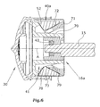
- FIGS. 6 and 7 shows a piston 30, which corresponds to that of the first embodiment.
- the propulsion actuator 16 a has an annular support part 41. On a hollow shaft 70 of the support member 41 is seated an annular pressure element 71 which is axially displaceable relative to the support member 41 and which is secured by a nut 43 on the drive rod 15.
- the support member 41 has a conical sliding surface 52 and the pressure element 51 also has a conical sliding surface 72.
- the sliding surfaces 52 and 72 are directed against each other, so that they form a receptacle in which the expansion part 40a sits in the form of a spreader 73.
- the propulsion actuator 16a is provided with a stretchable protective cover 75 which surrounds the expansion part 40 and the pressure element 71.
- the spreader 73 has a plurality of rigid segments 76 which are connected by elastic member 77.
- the elastic elements 77 may be integrally formed on the segments 76. They cause a radial extensibility of the expansion ring 73.
- the expansion ring 73 has oppositely inclined inclined surfaces 78, 79 which cooperate with the sliding surfaces 52 and 72.
- the expansion ring 73 does not necessarily consist of segments and elastic elements. It may also be an elastic O-ring, which is expanded by relative displacement of the pressure element 71 with respect to the support member 41.
- FIG. 8 schematically shows another embodiment of the driving actuator 16.
- This has two relatively rigid parallel plates, which are connected by a tubular flexible peripheral wall 62.
- the peripheral wall 62 encloses, together with the plates 60, 61, a fluid space 63 which is filled with liquid.
- the liquid is pressurized, so that it endeavors to expand the peripheral wall 62 laterally.
- the peripheral wall 62 is pressed against the side wall 31 of the piston 30.
Landscapes
- Engineering & Computer Science (AREA)
- Mechanical Engineering (AREA)
- Coating Apparatus (AREA)
Applications Claiming Priority (1)
| Application Number | Priority Date | Filing Date | Title |
|---|---|---|---|
| DE102008063502A DE102008063502A1 (de) | 2008-12-17 | 2008-12-17 | Auspresswerkzeug |
Publications (2)
| Publication Number | Publication Date |
|---|---|
| EP2198977A1 true EP2198977A1 (fr) | 2010-06-23 |
| EP2198977B1 EP2198977B1 (fr) | 2013-11-06 |
Family
ID=42103911
Family Applications (1)
| Application Number | Title | Priority Date | Filing Date |
|---|---|---|---|
| EP09179251.5A Active EP2198977B1 (fr) | 2008-12-17 | 2009-12-15 | Outil de compression |
Country Status (4)
| Country | Link |
|---|---|
| US (1) | US8342371B2 (fr) |
| EP (1) | EP2198977B1 (fr) |
| DE (1) | DE102008063502A1 (fr) |
| DK (1) | DK2198977T3 (fr) |
Cited By (1)
| Publication number | Priority date | Publication date | Assignee | Title |
|---|---|---|---|---|
| EP3852940A1 (fr) * | 2018-09-19 | 2021-07-28 | PRC-Desoto International, Inc. | Ensembles extensibles de tête de piston pour pistolets de distribution d'agent d'étanchéité |
Families Citing this family (11)
| Publication number | Priority date | Publication date | Assignee | Title |
|---|---|---|---|---|
| JP5767208B2 (ja) * | 2010-03-29 | 2015-08-19 | テルモ株式会社 | プレフィルドシリンジ |
| IT1401255B1 (it) * | 2010-06-14 | 2013-07-18 | Marchesini Group Spa | Dosatore volumetrico per dosare sostanze farmaceutiche liquide o pastose |
| JP2013537504A (ja) | 2010-08-16 | 2013-10-03 | バイエル・マテリアルサイエンス・アクチェンゲゼルシャフト | 吐出モジュール |
| US20130168413A1 (en) * | 2010-08-16 | 2013-07-04 | Bayer Materialscience Ag | Dispensing module and method for filling a dispensing module |
| DE102011004971A1 (de) * | 2011-03-02 | 2012-09-06 | Hilti Aktiengesellschaft | Auspressgerät |
| FR2997934B1 (fr) * | 2012-11-12 | 2015-06-19 | Aptar France Sas | Reservoir de produit fluide. |
| US9731317B2 (en) | 2014-10-15 | 2017-08-15 | Sonoco Development, Inc. | Device for holding and dispensing viscous material |
| JP6635698B2 (ja) * | 2015-07-14 | 2020-01-29 | ぺんてる株式会社 | 抵抗構造によりプランジャの可動範囲を制限したアプリケータ |
| EP3714994A1 (fr) * | 2019-03-26 | 2020-09-30 | Sulzer Mixpac AG | Piston, cartouche, distributeur |
| US11964297B2 (en) * | 2021-05-05 | 2024-04-23 | Richard Brewington | Caulk gun with a set of shortened rods |
| EP4464424A1 (fr) * | 2023-05-15 | 2024-11-20 | Henkel AG & Co. KGaA | Cartouche comprenant une unité de piston avec piston interne fendu |
Citations (2)
| Publication number | Priority date | Publication date | Assignee | Title |
|---|---|---|---|---|
| EP0867403A1 (fr) * | 1997-03-24 | 1998-09-30 | Sicpa Holding S.A. | Elément de raclage, piston et arrangement pour vider un sachet contenant und liquide pâteux |
| EP1908703A1 (fr) * | 2006-10-06 | 2008-04-09 | Sulzer Chemtech AG | Piston de cartouche |
Family Cites Families (20)
| Publication number | Priority date | Publication date | Assignee | Title |
|---|---|---|---|---|
| US103140A (en) * | 1870-05-17 | John clark | ||
| US1427647A (en) * | 1921-04-28 | 1922-08-29 | Ray C Sharp | Automatic expansible packing head |
| US2393747A (en) * | 1945-04-21 | 1946-01-29 | J D Buchanan | Expansible piston |
| US2887253A (en) * | 1956-11-07 | 1959-05-19 | R C Can Co | Slip cover and plunger for cartridge-container |
| US2958445A (en) * | 1958-10-30 | 1960-11-01 | Walter A Jesse | Plunger means for mortar gun |
| US3352213A (en) * | 1965-02-17 | 1967-11-14 | Raymond J Karol | Expansible reciprocating piston |
| US3501063A (en) * | 1968-04-05 | 1970-03-17 | Superior Mfg Co | Plunger assembly for multiloading hand grease guns |
| US3745890A (en) * | 1971-06-09 | 1973-07-17 | N Costarella | Ringless piston |
| DE7923330U1 (de) * | 1979-08-16 | 1979-11-08 | Teroson Gmbh | Kartusche |
| DE8705030U1 (de) * | 1986-07-30 | 1987-06-04 | Ara-Werk Krämer GmbH + Co, 7441 Unterensingen | Vorrichtung zum strangförmigen Austragen von pastösen Massen |
| EP0281755B1 (fr) * | 1987-02-13 | 1990-11-07 | Wilhelm A. Keller | Cartouche-distributrice à piston refoulant |
| DE4042065A1 (de) * | 1990-12-28 | 1992-07-02 | Friedhelm Schneider | Dosierpistole fuer schlauchbeutel mit hochviskosem inhalt |
| US5407332A (en) * | 1992-02-06 | 1995-04-18 | Graco Inc. | High suction intake wiper |
| PH31484A (en) * | 1992-12-22 | 1998-11-03 | Hosokawa Yoko Kk | Container, method of manufacturing the same and installation jig for cartridge container for d18scharge gun. |
| DE4331241B4 (de) * | 1993-09-15 | 2004-02-05 | Fte Automotive Gmbh | Hydraulischer Betätigungszylinder |
| US6334548B1 (en) * | 1999-04-22 | 2002-01-01 | Hosokawa Yoko Co., Ltd. | Plastic container formed by insert-injection process |
| JP4216096B2 (ja) * | 2002-03-13 | 2009-01-28 | キユーピー株式会社 | ガン式ディスペンサ |
| DE10342090B4 (de) * | 2003-09-10 | 2007-06-06 | Heraeus Kulzer Gmbh | Verschlusskolben für Kartuschen mit Entlüftung und Barriereeigenschaften |
| US7491191B2 (en) * | 2004-02-13 | 2009-02-17 | Liebel-Flarsheim Company | Keep vein open method and injector with keep vein open function |
| DE202008007834U1 (de) * | 2008-06-12 | 2008-08-21 | Gfv Verschlusstechnik Gmbh & Co. Kg | Kolben zum Auspressen von Füllsubstanzen |
-
2008
- 2008-12-17 DE DE102008063502A patent/DE102008063502A1/de not_active Withdrawn
-
2009
- 2009-12-15 EP EP09179251.5A patent/EP2198977B1/fr active Active
- 2009-12-15 US US12/638,757 patent/US8342371B2/en not_active Expired - Fee Related
- 2009-12-15 DK DK09179251.5T patent/DK2198977T3/da active
Patent Citations (2)
| Publication number | Priority date | Publication date | Assignee | Title |
|---|---|---|---|---|
| EP0867403A1 (fr) * | 1997-03-24 | 1998-09-30 | Sicpa Holding S.A. | Elément de raclage, piston et arrangement pour vider un sachet contenant und liquide pâteux |
| EP1908703A1 (fr) * | 2006-10-06 | 2008-04-09 | Sulzer Chemtech AG | Piston de cartouche |
Cited By (2)
| Publication number | Priority date | Publication date | Assignee | Title |
|---|---|---|---|---|
| EP3852940A1 (fr) * | 2018-09-19 | 2021-07-28 | PRC-Desoto International, Inc. | Ensembles extensibles de tête de piston pour pistolets de distribution d'agent d'étanchéité |
| EP3852940B1 (fr) * | 2018-09-19 | 2025-07-30 | PRC-Desoto International, Inc. | Ensembles extensibles de tête de piston pour pistolets de distribution d'agent d'étanchéité |
Also Published As
| Publication number | Publication date |
|---|---|
| EP2198977B1 (fr) | 2013-11-06 |
| DE102008063502A1 (de) | 2010-06-24 |
| US8342371B2 (en) | 2013-01-01 |
| US20100147895A1 (en) | 2010-06-17 |
| DK2198977T3 (da) | 2014-01-20 |
Similar Documents
| Publication | Publication Date | Title |
|---|---|---|
| EP2198977B1 (fr) | Outil de compression | |
| DE69937896T2 (de) | Pipette mit verbesserter pipettenspitze und verbesserter montage-achse | |
| EP0006430B1 (fr) | Réservoir tubulaire pour seringue médicale pour mélanger et fournir des produits pâteux | |
| DE69813425T2 (de) | Behälter mit einer Volumenreduktionsvorrichtung | |
| DE3920537C2 (de) | Mehrkomponenten-Mischkapsel mit Ausspritzeinrichtung für die gemischte Masse, insbesondere für Dentalzwecke | |
| EP1735110B1 (fr) | Pistolet a mastic pourvu d'un element de retenue de cartouche | |
| CH679146A5 (fr) | ||
| DE19943877A1 (de) | Zweikomponentenkartusche für fließfähige Medien | |
| EP2883603A1 (fr) | Dispositif de stockage et de mélange de ciment osseux | |
| DE202014011125U1 (de) | Innengreifer | |
| DE102008037686B4 (de) | Behälter und Kolbenstangenanordnung sowie deren Verwendung | |
| DE102007060382B4 (de) | Aufschneidvorrichtung zum Öffnen eines Schlauchbeutels | |
| DE3823708C2 (de) | Motorisch angetriebene Einrichtung zum Dosieren und Mischen von wenigstens zwei Substanzen | |
| EP4151321B1 (fr) | Structure de soutien ayant un diamètre intérieur variable permettant de presser sans force de retour d'une masse à composants multiples à partir d'une cartouche coaxiale | |
| EP2412529A2 (fr) | Conteneur d'encre pour imprimante à tampon, dispositif de nettoyage pour conteneur d'encre et imprimante à tampon | |
| DE102009007116B4 (de) | Behälter mit Ventil für eine Abgabepistole und Abgabesystem | |
| EP0594974A1 (fr) | Outil d'extrusion pour masse pâteuse contenue dans une enveloppe flexible | |
| DE102007061696A1 (de) | Vorrichtung zum Vermischen von Knochenzement | |
| DE9218334U1 (de) | Mehr-Komponenten-Verarbeitungsvorrichtung | |
| DE4231420A1 (de) | Kolben für Auspressgeräte | |
| EP2062821A1 (fr) | Dispositif de remplissage d'un récipient avec un liquide | |
| DE2404549B2 (de) | Vorrichtung zum Formen einer Verbindungsmuffe am Endabschnitt eines Rohres aus thermoplastischem Kunststoff | |
| DE202007016705U1 (de) | Beutelschmelzer | |
| WO1999026865A1 (fr) | Cartouche destinee a des matieres pateuses | |
| DE1480873C (de) | Werkzeug und Pfropfen zum Verschließen von Löchern in einem auf der Felge belassenen, schlauchlosen Luftreifen |
Legal Events
| Date | Code | Title | Description |
|---|---|---|---|
| PUAI | Public reference made under article 153(3) epc to a published international application that has entered the european phase |
Free format text: ORIGINAL CODE: 0009012 |
|
| AK | Designated contracting states |
Kind code of ref document: A1 Designated state(s): AT BE BG CH CY CZ DE DK EE ES FI FR GB GR HR HU IE IS IT LI LT LU LV MC MK MT NL NO PL PT RO SE SI SK SM TR |
|
| 17P | Request for examination filed |
Effective date: 20101002 |
|
| 17Q | First examination report despatched |
Effective date: 20121025 |
|
| GRAP | Despatch of communication of intention to grant a patent |
Free format text: ORIGINAL CODE: EPIDOSNIGR1 |
|
| INTG | Intention to grant announced |
Effective date: 20130528 |
|
| GRAS | Grant fee paid |
Free format text: ORIGINAL CODE: EPIDOSNIGR3 |
|
| GRAA | (expected) grant |
Free format text: ORIGINAL CODE: 0009210 |
|
| AK | Designated contracting states |
Kind code of ref document: B1 Designated state(s): AT BE BG CH CY CZ DE DK EE ES FI FR GB GR HR HU IE IS IT LI LT LU LV MC MK MT NL NO PL PT RO SE SI SK SM TR |
|
| REG | Reference to a national code |
Ref country code: GB Ref legal event code: FG4D Free format text: NOT ENGLISH |
|
| REG | Reference to a national code |
Ref country code: CH Ref legal event code: EP |
|
| REG | Reference to a national code |
Ref country code: CH Ref legal event code: NV Representative=s name: ISLER AND PEDRAZZINI AG, CH |
|
| REG | Reference to a national code |
Ref country code: AT Ref legal event code: REF Ref document number: 639075 Country of ref document: AT Kind code of ref document: T Effective date: 20131215 |
|
| REG | Reference to a national code |
Ref country code: IE Ref legal event code: FG4D Free format text: LANGUAGE OF EP DOCUMENT: GERMAN |
|
| REG | Reference to a national code |
Ref country code: DE Ref legal event code: R096 Ref document number: 502009008283 Country of ref document: DE Effective date: 20140102 |
|
| REG | Reference to a national code |
Ref country code: DK Ref legal event code: T3 Effective date: 20140117 |
|
| REG | Reference to a national code |
Ref country code: NL Ref legal event code: T3 |
|
| REG | Reference to a national code |
Ref country code: LT Ref legal event code: MG4D |
|
| PG25 | Lapsed in a contracting state [announced via postgrant information from national office to epo] |
Ref country code: LT Free format text: LAPSE BECAUSE OF FAILURE TO SUBMIT A TRANSLATION OF THE DESCRIPTION OR TO PAY THE FEE WITHIN THE PRESCRIBED TIME-LIMIT Effective date: 20131106 Ref country code: NO Free format text: LAPSE BECAUSE OF FAILURE TO SUBMIT A TRANSLATION OF THE DESCRIPTION OR TO PAY THE FEE WITHIN THE PRESCRIBED TIME-LIMIT Effective date: 20140206 Ref country code: IS Free format text: LAPSE BECAUSE OF FAILURE TO SUBMIT A TRANSLATION OF THE DESCRIPTION OR TO PAY THE FEE WITHIN THE PRESCRIBED TIME-LIMIT Effective date: 20140306 Ref country code: SE Free format text: LAPSE BECAUSE OF FAILURE TO SUBMIT A TRANSLATION OF THE DESCRIPTION OR TO PAY THE FEE WITHIN THE PRESCRIBED TIME-LIMIT Effective date: 20131106 Ref country code: HR Free format text: LAPSE BECAUSE OF FAILURE TO SUBMIT A TRANSLATION OF THE DESCRIPTION OR TO PAY THE FEE WITHIN THE PRESCRIBED TIME-LIMIT Effective date: 20131106 Ref country code: FI Free format text: LAPSE BECAUSE OF FAILURE TO SUBMIT A TRANSLATION OF THE DESCRIPTION OR TO PAY THE FEE WITHIN THE PRESCRIBED TIME-LIMIT Effective date: 20131106 |
|
| PG25 | Lapsed in a contracting state [announced via postgrant information from national office to epo] |
Ref country code: ES Free format text: LAPSE BECAUSE OF FAILURE TO SUBMIT A TRANSLATION OF THE DESCRIPTION OR TO PAY THE FEE WITHIN THE PRESCRIBED TIME-LIMIT Effective date: 20131106 Ref country code: LV Free format text: LAPSE BECAUSE OF FAILURE TO SUBMIT A TRANSLATION OF THE DESCRIPTION OR TO PAY THE FEE WITHIN THE PRESCRIBED TIME-LIMIT Effective date: 20131106 |
|
| PG25 | Lapsed in a contracting state [announced via postgrant information from national office to epo] |
Ref country code: PT Free format text: LAPSE BECAUSE OF FAILURE TO SUBMIT A TRANSLATION OF THE DESCRIPTION OR TO PAY THE FEE WITHIN THE PRESCRIBED TIME-LIMIT Effective date: 20140306 |
|
| PG25 | Lapsed in a contracting state [announced via postgrant information from national office to epo] |
Ref country code: EE Free format text: LAPSE BECAUSE OF FAILURE TO SUBMIT A TRANSLATION OF THE DESCRIPTION OR TO PAY THE FEE WITHIN THE PRESCRIBED TIME-LIMIT Effective date: 20131106 |
|
| REG | Reference to a national code |
Ref country code: DE Ref legal event code: R097 Ref document number: 502009008283 Country of ref document: DE |
|
| PG25 | Lapsed in a contracting state [announced via postgrant information from national office to epo] |
Ref country code: PL Free format text: LAPSE BECAUSE OF FAILURE TO SUBMIT A TRANSLATION OF THE DESCRIPTION OR TO PAY THE FEE WITHIN THE PRESCRIBED TIME-LIMIT Effective date: 20131106 Ref country code: CZ Free format text: LAPSE BECAUSE OF FAILURE TO SUBMIT A TRANSLATION OF THE DESCRIPTION OR TO PAY THE FEE WITHIN THE PRESCRIBED TIME-LIMIT Effective date: 20131106 Ref country code: IT Free format text: LAPSE BECAUSE OF FAILURE TO SUBMIT A TRANSLATION OF THE DESCRIPTION OR TO PAY THE FEE WITHIN THE PRESCRIBED TIME-LIMIT Effective date: 20131106 Ref country code: RO Free format text: LAPSE BECAUSE OF FAILURE TO SUBMIT A TRANSLATION OF THE DESCRIPTION OR TO PAY THE FEE WITHIN THE PRESCRIBED TIME-LIMIT Effective date: 20131106 Ref country code: SK Free format text: LAPSE BECAUSE OF FAILURE TO SUBMIT A TRANSLATION OF THE DESCRIPTION OR TO PAY THE FEE WITHIN THE PRESCRIBED TIME-LIMIT Effective date: 20131106 Ref country code: MC Free format text: LAPSE BECAUSE OF FAILURE TO SUBMIT A TRANSLATION OF THE DESCRIPTION OR TO PAY THE FEE WITHIN THE PRESCRIBED TIME-LIMIT Effective date: 20131106 |
|
| PLBE | No opposition filed within time limit |
Free format text: ORIGINAL CODE: 0009261 |
|
| STAA | Information on the status of an ep patent application or granted ep patent |
Free format text: STATUS: NO OPPOSITION FILED WITHIN TIME LIMIT |
|
| REG | Reference to a national code |
Ref country code: IE Ref legal event code: MM4A |
|
| 26N | No opposition filed |
Effective date: 20140807 |
|
| PG25 | Lapsed in a contracting state [announced via postgrant information from national office to epo] |
Ref country code: IE Free format text: LAPSE BECAUSE OF NON-PAYMENT OF DUE FEES Effective date: 20131215 |
|
| REG | Reference to a national code |
Ref country code: DE Ref legal event code: R097 Ref document number: 502009008283 Country of ref document: DE Effective date: 20140807 |
|
| PG25 | Lapsed in a contracting state [announced via postgrant information from national office to epo] |
Ref country code: SI Free format text: LAPSE BECAUSE OF FAILURE TO SUBMIT A TRANSLATION OF THE DESCRIPTION OR TO PAY THE FEE WITHIN THE PRESCRIBED TIME-LIMIT Effective date: 20131106 |
|
| PG25 | Lapsed in a contracting state [announced via postgrant information from national office to epo] |
Ref country code: SM Free format text: LAPSE BECAUSE OF FAILURE TO SUBMIT A TRANSLATION OF THE DESCRIPTION OR TO PAY THE FEE WITHIN THE PRESCRIBED TIME-LIMIT Effective date: 20131106 |
|
| PG25 | Lapsed in a contracting state [announced via postgrant information from national office to epo] |
Ref country code: TR Free format text: LAPSE BECAUSE OF FAILURE TO SUBMIT A TRANSLATION OF THE DESCRIPTION OR TO PAY THE FEE WITHIN THE PRESCRIBED TIME-LIMIT Effective date: 20131106 Ref country code: CY Free format text: LAPSE BECAUSE OF FAILURE TO SUBMIT A TRANSLATION OF THE DESCRIPTION OR TO PAY THE FEE WITHIN THE PRESCRIBED TIME-LIMIT Effective date: 20131106 |
|
| PG25 | Lapsed in a contracting state [announced via postgrant information from national office to epo] |
Ref country code: LU Free format text: LAPSE BECAUSE OF NON-PAYMENT OF DUE FEES Effective date: 20131215 Ref country code: HU Free format text: LAPSE BECAUSE OF FAILURE TO SUBMIT A TRANSLATION OF THE DESCRIPTION OR TO PAY THE FEE WITHIN THE PRESCRIBED TIME-LIMIT; INVALID AB INITIO Effective date: 20091215 Ref country code: MK Free format text: LAPSE BECAUSE OF FAILURE TO SUBMIT A TRANSLATION OF THE DESCRIPTION OR TO PAY THE FEE WITHIN THE PRESCRIBED TIME-LIMIT Effective date: 20131106 Ref country code: BG Free format text: LAPSE BECAUSE OF FAILURE TO SUBMIT A TRANSLATION OF THE DESCRIPTION OR TO PAY THE FEE WITHIN THE PRESCRIBED TIME-LIMIT Effective date: 20131106 |
|
| PG25 | Lapsed in a contracting state [announced via postgrant information from national office to epo] |
Ref country code: MT Free format text: LAPSE BECAUSE OF FAILURE TO SUBMIT A TRANSLATION OF THE DESCRIPTION OR TO PAY THE FEE WITHIN THE PRESCRIBED TIME-LIMIT Effective date: 20131106 Ref country code: GR Free format text: LAPSE BECAUSE OF NON-PAYMENT OF DUE FEES Effective date: 20131106 |
|
| REG | Reference to a national code |
Ref country code: FR Ref legal event code: PLFP Year of fee payment: 7 |
|
| REG | Reference to a national code |
Ref country code: AT Ref legal event code: MM01 Ref document number: 639075 Country of ref document: AT Kind code of ref document: T Effective date: 20141215 |
|
| PG25 | Lapsed in a contracting state [announced via postgrant information from national office to epo] |
Ref country code: AT Free format text: LAPSE BECAUSE OF NON-PAYMENT OF DUE FEES Effective date: 20141215 |
|
| PG25 | Lapsed in a contracting state [announced via postgrant information from national office to epo] |
Ref country code: GR Free format text: LAPSE BECAUSE OF FAILURE TO SUBMIT A TRANSLATION OF THE DESCRIPTION OR TO PAY THE FEE WITHIN THE PRESCRIBED TIME-LIMIT Effective date: 20140207 |
|
| REG | Reference to a national code |
Ref country code: FR Ref legal event code: PLFP Year of fee payment: 8 |
|
| PGFP | Annual fee paid to national office [announced via postgrant information from national office to epo] |
Ref country code: NL Payment date: 20161221 Year of fee payment: 8 Ref country code: CH Payment date: 20161222 Year of fee payment: 8 |
|
| PGFP | Annual fee paid to national office [announced via postgrant information from national office to epo] |
Ref country code: BE Payment date: 20161221 Year of fee payment: 8 |
|
| REG | Reference to a national code |
Ref country code: FR Ref legal event code: PLFP Year of fee payment: 9 |
|
| PGFP | Annual fee paid to national office [announced via postgrant information from national office to epo] |
Ref country code: DK Payment date: 20171221 Year of fee payment: 9 |
|
| REG | Reference to a national code |
Ref country code: CH Ref legal event code: PL |
|
| REG | Reference to a national code |
Ref country code: NL Ref legal event code: MM Effective date: 20180101 |
|
| PG25 | Lapsed in a contracting state [announced via postgrant information from national office to epo] |
Ref country code: NL Free format text: LAPSE BECAUSE OF NON-PAYMENT OF DUE FEES Effective date: 20180101 |
|
| REG | Reference to a national code |
Ref country code: BE Ref legal event code: MM Effective date: 20171231 |
|
| PG25 | Lapsed in a contracting state [announced via postgrant information from national office to epo] |
Ref country code: LI Free format text: LAPSE BECAUSE OF NON-PAYMENT OF DUE FEES Effective date: 20171231 Ref country code: CH Free format text: LAPSE BECAUSE OF NON-PAYMENT OF DUE FEES Effective date: 20171231 Ref country code: BE Free format text: LAPSE BECAUSE OF NON-PAYMENT OF DUE FEES Effective date: 20171231 |
|
| REG | Reference to a national code |
Ref country code: DK Ref legal event code: EBP Effective date: 20181231 |
|
| PG25 | Lapsed in a contracting state [announced via postgrant information from national office to epo] |
Ref country code: DK Free format text: LAPSE BECAUSE OF NON-PAYMENT OF DUE FEES Effective date: 20181231 |
|
| PGFP | Annual fee paid to national office [announced via postgrant information from national office to epo] |
Ref country code: FR Payment date: 20201218 Year of fee payment: 12 |
|
| PG25 | Lapsed in a contracting state [announced via postgrant information from national office to epo] |
Ref country code: FR Free format text: LAPSE BECAUSE OF NON-PAYMENT OF DUE FEES Effective date: 20211231 |
|
| P01 | Opt-out of the competence of the unified patent court (upc) registered |
Effective date: 20230502 |
|
| PGFP | Annual fee paid to national office [announced via postgrant information from national office to epo] |
Ref country code: DE Payment date: 20251015 Year of fee payment: 17 |
|
| PGFP | Annual fee paid to national office [announced via postgrant information from national office to epo] |
Ref country code: GB Payment date: 20251218 Year of fee payment: 17 |