EP2198993A1 - Sinterverfahren und -vorrichtung - Google Patents
Sinterverfahren und -vorrichtung Download PDFInfo
- Publication number
- EP2198993A1 EP2198993A1 EP08425809A EP08425809A EP2198993A1 EP 2198993 A1 EP2198993 A1 EP 2198993A1 EP 08425809 A EP08425809 A EP 08425809A EP 08425809 A EP08425809 A EP 08425809A EP 2198993 A1 EP2198993 A1 EP 2198993A1
- Authority
- EP
- European Patent Office
- Prior art keywords
- pressure
- powders
- mould
- increment
- time interval
- Prior art date
- Legal status (The legal status is an assumption and is not a legal conclusion. Google has not performed a legal analysis and makes no representation as to the accuracy of the status listed.)
- Granted
Links
Images


Classifications
-
- B—PERFORMING OPERATIONS; TRANSPORTING
- B22—CASTING; POWDER METALLURGY
- B22F—WORKING METALLIC POWDER; MANUFACTURE OF ARTICLES FROM METALLIC POWDER; MAKING METALLIC POWDER; APPARATUS OR DEVICES SPECIALLY ADAPTED FOR METALLIC POWDER
- B22F3/00—Manufacture of workpieces or articles from metallic powder characterised by the manner of compacting or sintering; Apparatus specially adapted therefor ; Presses and furnaces
- B22F3/12—Both compacting and sintering
- B22F3/14—Both compacting and sintering simultaneously
-
- H—ELECTRICITY
- H01—ELECTRIC ELEMENTS
- H01F—MAGNETS; INDUCTANCES; TRANSFORMERS; SELECTION OF MATERIALS FOR THEIR MAGNETIC PROPERTIES
- H01F41/00—Apparatus or processes specially adapted for manufacturing or assembling magnets, inductances or transformers; Apparatus or processes specially adapted for manufacturing materials characterised by their magnetic properties
- H01F41/02—Apparatus or processes specially adapted for manufacturing or assembling magnets, inductances or transformers; Apparatus or processes specially adapted for manufacturing materials characterised by their magnetic properties for manufacturing cores, coils, or magnets
- H01F41/0253—Apparatus or processes specially adapted for manufacturing or assembling magnets, inductances or transformers; Apparatus or processes specially adapted for manufacturing materials characterised by their magnetic properties for manufacturing cores, coils, or magnets for manufacturing permanent magnets
- H01F41/0266—Moulding; Pressing
-
- B—PERFORMING OPERATIONS; TRANSPORTING
- B22—CASTING; POWDER METALLURGY
- B22F—WORKING METALLIC POWDER; MANUFACTURE OF ARTICLES FROM METALLIC POWDER; MAKING METALLIC POWDER; APPARATUS OR DEVICES SPECIALLY ADAPTED FOR METALLIC POWDER
- B22F2998/00—Supplementary information concerning processes or compositions relating to powder metallurgy
-
- B—PERFORMING OPERATIONS; TRANSPORTING
- B22—CASTING; POWDER METALLURGY
- B22F—WORKING METALLIC POWDER; MANUFACTURE OF ARTICLES FROM METALLIC POWDER; MAKING METALLIC POWDER; APPARATUS OR DEVICES SPECIALLY ADAPTED FOR METALLIC POWDER
- B22F2999/00—Aspects linked to processes or compositions used in powder metallurgy
Definitions
- the present invention relates to a sintering process for powders consisting of conductive powders, loose or in the form of powder compacts, comprising the operations of:
- Sintering is the process through which powders are densified into a determined shape with specific mechanical, electromagnetic and thermal properties resulting from the shape, material microstructure and residual porosity thusly obtained.
- An industrial sintering process usually requires operation of:
- Sintering techniques present recurring drawbacks, such as a long processing time due to the time necessary to reach homogeneous temperatures in the green bodies and obtain sintering, or incomplete or partial densification due to an inefficient conduction or convection in the ovens.
- Non homogenous densification can occur also in green bodies that are poorly pre-compacted.
- a micro structural alteration can also occur due to the high temperatures and long time necessary to obtain full density.
- the sintering process for electrically conductive materials can be carried out with the aid of electrical currents for the purpose of reducing processing time in a significant manner.
- the powders or green bodies When sintering is electrically assisted, the powders or green bodies must be positioned in appropriately designed moulds and therefore, rams are provided that function also as electrodes to convey the electrical current to the powders and to apply the mechanical pressure to them.
- the reduction in sintering time by electrical current has successively reached a limit of a few hundreds of microseconds per cycle with the adoption of discharge circuits that direct the energy stored in a capacitor to a compacted powder under pressure.
- the discharge method also requires the use of high-voltage vacuum ion switches that are unreliable and must therefore be replaced frequently, not to mention that they are subject to localisation of the currents in the form of plasma due to the high voltages in the powders.
- Processes are known that improve the quality of the compacted and sintered bodies and at the same time obtain a reduction in processing time through a procedure that envisions applying currents and exerting high pressure on the powders.
- the present invention has for object to overcome the drawbacks of the prior art and obtain a sintering process solution allowing operation at high energy densities, obtaining greater densification and more homogeneity with respect to known processes and a better process control.
- the proposed sintering process envisions to employ one or more electromagnetic energy impulses, in particular single, double or multiple impulses, provided through electrodes that operate also as moulds and/or as rams on the powders or powder compacts to be sintered.
- electromagnetic energy impulses are combined with synchronised pulses, i.e., increases of mechanical pressure, with the goal of concentrating the applied energy into the inter-particle contacts.
- Each pulse of electromagnetic energy must be sufficiently intense to provide values of specific electromagnetic energy in the powders or powder compacts of at least 500 J/g measured in the working element as the integral of the product of the real part of the current and the voltage, calculated over the duration of the electromagnetic energy impulse.
- Continuous monitoring of the movement of the rams, the pressure, the voltage and the current during the process is envisioned to allow interruption of the electromagnetic energy supply circuit in case of uncontrolled fluctuations of the process parameters and to provide detailed information regarding the working component.
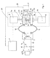
- FIG. 1 a schematic diagram is shown of a sintering system suitable for carrying out the sintering process according to the invention.
- Such sintering system comprises, an AC-DC converter indicated with the numerical reference 1, for example a rectifier, connected to a power source not shown in Figure 1 .
- a switch 13 separates the output of such converter 1 from a bank of capacitors 2 arranged in parallel, while a second switch 14, connected downstream of such capacitor bank 2, separates it from the input terminals 7 of a transformer 3.
- Such switches 13 and 14 operate under the control of a process control unit 4, which commands their opening and closing states, allowing the bank of capacitors 2 to be charged to the desired charge levels, maintaining switch 13 closed and switch 14 in the open position.
- switch 13 is opened and switch 14 is closed, permitting the impulse of current determined by the charge in the capacitors 2 to reach the transformer 3.
- Output terminals 8 from the secondary of the transformer 3 are connected by means of cable conductors 11 and 12 to conductive plates 9 and 10 that are part of the pressing system 29.
- Such pressing system 29 comprises respective pressing devices 5 and 6 that operate under the control of the process control unit 4.
- Such pressing devices 5 and 6 can be, for example, screw presses, or oil hydraulic presses with membrane accumulators or an equivalent system apt to apply a pressure according to the mode envisioned by the process according to the invention and described in greater detail in the following.
- the pressing device 5 comprises, as mentioned, an actuator 5a that is connected by means of a stem 5b to a plate 9, which carries a ram 21 that is also conductive.
- the pressing device 6 comprises a respective actuator 6a, connected by means of a respective stem 6b to a plate 20 and a respective conductive ram 22.
- a cylindrical mould with non-conductive side walls is indicated with numerical reference 23.
- the rams 21 and 22 operate in such mould 23 along the principle axis of the cylinder identified by such mould 23 in opposite directions to compress the conductive powders D.
- the rams 21 and 22 are conductive, and thus function as electrodes in electrical continuity with the transformer 3.
- the voltage signal is brought to an oscilloscope 17 through sampling electrodes 20 applied to each of the plates 9 or 10 and respective insulated cables 16.
- a Rogowsky coil 18 arranged around the mould 23 is also connected to the oscilloscope 17 through a signal integrator 19 to monitor the electrical current in it.
- the oscilloscope 17 is connected by means of a communication line 25, for example a serial line, to the process control unit 4, which, in this way can monitor the movement of the rams, the pressure, the voltage and current in a continuous manner during the process, for the purpose, for example, of interrupting the electromagnetic energy supply circuit in case of uncontrolled fluctuations in process parameters and to provide detailed information regarding the working component.
- the switch 13 is opened, while the rams 21 and 22 are actuated to apply a first pressure P 0 , by way of example such first pressure P 0 being comprised between 5 and 20 MPa, to assure good electrical contact with the powders D.
- the process control unit 4 sets the switch 14 to the closed position, releasing a current impulse I i and commands the actuation by the pressing devices 5 and 6 to increase the pressure P i having a determined temporal trend.
- Such current impulses I i and pressure increases P i are described in more detail with reference to Figures 3 and 4 , but, in general the increase in pressure P i is characterised by an increase in pressure from a first pressure P 0 to a second pressure P 1 , said second pressure P 1 being for example variable in the range from 50-500 MPa.
- the pressing devices 5 and 6 increase the pressure from the first pressure P 0 to the second pressure P 1 in a time interval included between a maximum time instant t m of the current impulse I i and a final time t f of the current impulse I i .
- a temporal diagram is shown in which the current in the powders is represented as a function of time i(t) showing the current impulse I i , which initiates at time zero of the temporal diagram, reaches the maximum at t m and terminates the discharge of the capacitors at the end time t f .
- a first operational mode is detailed in which the pressure as a function of time P(t) shows an increase in pressure, in particular a linear or monotonic increasing ramp, from a first pressure P 0 to a second pressure P 1 , such increase commencing in correspondence to time instant zero and ending in correspondence to the finish time instant t f .
- the process envisions the application of one or more current impulses for a respective time interval of predetermined duration, which corresponds to the duration between time instant zero at the beginning and the finish time instant t f , to apply the pressure exerting an increase P i of its value from a first pressure value P 0 to a second pressure value P 1 , the pressure increase P i being applied in the time interval of predetermined duration of the current impulse I i in a synchronised manner with respect to its initiation time instant, i.e. the pressure increase P i initiates in the same instant that the current impulse I i initiates, and in a distributed way in such time interval of predetermined duration.
- the pressure P(t), after having reached the second pressure P 1 , can be maintained constant for a certain time or diminish.
- the variations in pressure can increase uniformly or discontinuously or in any case increase so that the final value, that is, the second pressure value P 1 , greater that the initial one, the first pressure value P 0 , is reached during the current impulse, and coincides with the maximum time t m of the current impulse I i or with the final time t f of the impulse or it occurs in a position intermediate between the two times t m and t f .
- one ram can be controlled to execute a first pressure ramp with a first slope and the other ram can be controlled to execute a second pressure ramp, in the same arc of time, but with a second slope different from the first, i.e. reaching a greater or lesser final pressure. In this way a porosity gradient is obtained in the produced object.
- the entire process can be carried out in a controlled manner, performing feedback control of the rams commanded by the values of voltage and/or current and/or energy and/or electrical resistance and/or sinking depth that can be monitored with the oscilloscope and/or other possible measurable physical quantities.
- multiple impulses can be used as multiple steps in a classical powder forging.
- a different value of specific energy can be associated with each compression step, that by acting on locally different structures and geometries will be distributed in a controlled manner to facilitate the movement of material and sintering.
- the voltage accumulated in the capacitor bank 2 is discharged through the step-down type transformer 3 onto a chain of resistive elements arranged downstream of the secondary of said transformer 3, which comprises the electrically conductive elements 8, 9, 10, 11, 12, 21, 22.
- the mould 23 can be constituted of, or coated internally with, dielectric material with conductivity lower than that of the loose powder or that of the powder compact.
- Figure 2 shows a detail of an alternative embodiment of the sintering system of Figure 1 .
- the dielectric mould 23 with a mould that forms a parallelepiped shaped cavity arranged horizontally in figure, having two conductive elements 33 and 34, respectively upper and lower, through which the current flows into the powders D.
- Such conductive elements 33 and 34 are connected to cables 11 and 12 in Figure 1 , while the pressure is applied to the powders D by means of non-conductive rams 31 and 32, which in Figure 2 operate axially with respect to the cavity of the mould and in a horizontal direction, exerting a force F.
- the forces operating on the two rams 31 and 32, in this embodiment as in the previous, are not necessarily identical, for example when a non-homogenous densification or a porosity gradient is required in the sintered body.
- the process can be completely executed in air.
- the sintering process according to the invention envisions the application of voltage drops v(t) with magnitudes between 30V and 3000V.
- the proposed sintering process and system allow porous, partially porous or full density sintered objects to be obtained with variations of the process parameters and of the mould and/or ram geometries used.
- full density sintered objects are obtained with little or no inter-atomic diffusion, therefore, during the process little or no increase in particle size is caused, leaving in this way essentially unaltered the microstructure of the powders used. In this way mechanical properties such as resistance to stress and hardness are enhanced.
- the proposed sintering process allows optimisation of the available energy on the surface of the powder particles and avoids unnecessary dissipation.
- the proposed sintering process envisions a flexible process for obtaining sintered bodies with full density or with a porosity density gradient, in particular for applications that require porous or partially porous bodies, such as for example bearings.
- the proposed sintering process allows the forming and forging of the powders during sintering, increasing their density and shaping them in an appropriately designed mould when needed.
- the sintering process according to the invention envisions increases of pressure during the process. This implies maintaining and increasing the pressure exerted on the powders during the current impulse.
- fast presses such as mechanical screw presses or oleo hydraulic presses in which the pistons are integrated with membrane accumulators in order to obtain an impulse of mechanical force contemporaneously with the discharge.
- the pressure values provided in the examples are indicative and could vary from material to material according to experimental evidence.
- the powders to be sintered, loose or compacted can be a mixture of conductive and non-conductive powders.
- mould used could have forms different from the cylindrical form illustrated as an example, according to the needs of the body to be sintered.
Landscapes
- Engineering & Computer Science (AREA)
- Manufacturing & Machinery (AREA)
- Power Engineering (AREA)
- Mechanical Engineering (AREA)
- Powder Metallurgy (AREA)
- Physics & Mathematics (AREA)
- Optics & Photonics (AREA)
Priority Applications (4)
| Application Number | Priority Date | Filing Date | Title |
|---|---|---|---|
| EP08425809A EP2198993B1 (de) | 2008-12-19 | 2008-12-19 | Sinterverfahren und -vorrichtung |
| US13/140,940 US9227244B2 (en) | 2008-12-19 | 2009-12-18 | Sintering process and corresponding sintering system |
| PCT/IB2009/055857 WO2010070623A2 (en) | 2008-12-19 | 2009-12-18 | Sintering process and corresponding sintering system |
| CN2009801571322A CN102325615A (zh) | 2008-12-19 | 2009-12-18 | 烧结过程和对应的烧结系统 |
Applications Claiming Priority (1)
| Application Number | Priority Date | Filing Date | Title |
|---|---|---|---|
| EP08425809A EP2198993B1 (de) | 2008-12-19 | 2008-12-19 | Sinterverfahren und -vorrichtung |
Publications (2)
| Publication Number | Publication Date |
|---|---|
| EP2198993A1 true EP2198993A1 (de) | 2010-06-23 |
| EP2198993B1 EP2198993B1 (de) | 2012-09-26 |
Family
ID=40688398
Family Applications (1)
| Application Number | Title | Priority Date | Filing Date |
|---|---|---|---|
| EP08425809A Active EP2198993B1 (de) | 2008-12-19 | 2008-12-19 | Sinterverfahren und -vorrichtung |
Country Status (4)
| Country | Link |
|---|---|
| US (1) | US9227244B2 (de) |
| EP (1) | EP2198993B1 (de) |
| CN (1) | CN102325615A (de) |
| WO (1) | WO2010070623A2 (de) |
Cited By (4)
| Publication number | Priority date | Publication date | Assignee | Title |
|---|---|---|---|---|
| EP3147918A1 (de) | 2015-09-25 | 2017-03-29 | Wilo Se | Vorrichtung und verfahren zur herstellung ringförmiger permanentmagnete |
| EP3208015A1 (de) | 2016-02-19 | 2017-08-23 | Fundación Tecnalia Research & Innovation | Verfahren zum sintern von elektrisch leitfähigen pulvern und vorrichtung zur durchführung des besagten verfahrens |
| EP3518258A4 (de) * | 2016-09-23 | 2020-06-24 | Nitto Denko Corporation | Verfahren zur herstellung eines gesinterten körpers zur herstellung eines gesinterten magneten und verfahren zur herstellung eines dauermagneten mit dem gesinterten körper zur herstellung eines gesinterten magneten |
| EP3702065A1 (de) * | 2019-02-28 | 2020-09-02 | Siemens Aktiengesellschaft | Sinter-vorrichtung mit voneinander entkoppeltem sinter-druck und sinter-strom, verfahren zum herstellen eines elektrischen kontakt-werkstoffs unter verwendung der sinter-vorrichtung, elektrischer kontakt-werkstoff und verwendung des elektrischen kontakt-werkstoffs |
Families Citing this family (13)
| Publication number | Priority date | Publication date | Assignee | Title |
|---|---|---|---|---|
| WO2012068492A1 (en) * | 2010-11-18 | 2012-05-24 | Zimmer, Inc. | Resistance welding a porous metal layer to a metal substrate |
| US10427235B2 (en) * | 2010-11-18 | 2019-10-01 | Zimmer, Inc. | Resistance welding a porous metal layer to a metal substrate |
| KR101311480B1 (ko) * | 2011-08-03 | 2013-11-13 | 한국생산기술연구원 | 마찰교반 접합툴용 텅스텐 카바이드 소결체 제조 방법 |
| EP2606996A1 (de) | 2011-12-23 | 2013-06-26 | EPoS S.r.L. | Verfahren zum Sinter von Metallmatrixverbundmaterialien |
| CN102765946B (zh) * | 2012-07-05 | 2013-12-25 | 中国科学院宁波材料技术与工程研究所 | 一种电流辅助快速制备粉体的方法 |
| PL229399B1 (pl) | 2013-03-28 | 2018-07-31 | Genicore Spolka Z Ograniczona Odpowiedzialnoscia | Urządzenie z wielkoprądowym łącznikiem elektronicznym dla konsolidacji materiałów proszkowych oraz sposób konsolidacji materiałów proszkowych za pomocą urządzenia z wielkoprądowym łącznikiem elektronicznym |
| JP2016078036A (ja) * | 2014-10-10 | 2016-05-16 | トヨタ自動車株式会社 | スポット溶接用電極 |
| PL234046B1 (pl) | 2014-11-03 | 2020-01-31 | Genicore Spolka Z Ograniczona Odpowiedzialnoscia | Sposób oraz urządzenie do konsolidacji materiałów proszkowych |
| CN105478777B (zh) * | 2015-12-14 | 2018-02-06 | 中国航空工业集团公司北京航空制造工程研究所 | 一种金属/陶瓷梯度材料及其制备方法 |
| US10946592B2 (en) * | 2016-09-11 | 2021-03-16 | Impossible Objects, Inc. | Resistive heating-compression method and apparatus for composite-based additive manufacturing |
| EP3862110A1 (de) | 2020-02-07 | 2021-08-11 | EPoS S.r.L. | Magnetische verbundmaterialien und verfahren zu ihrer herstellung |
| EP3903965B1 (de) | 2020-04-30 | 2023-11-29 | EPoS Technologies SA | Verfahren zur herstellung von gebundenen filtermaterialien |
| US12465971B1 (en) * | 2022-02-14 | 2025-11-11 | Triad National Security, Llc | Equipment for simultaneous or near-simultaneous flash sintering and forging |
Citations (6)
| Publication number | Priority date | Publication date | Assignee | Title |
|---|---|---|---|---|
| US2355954A (en) | 1942-03-04 | 1944-08-15 | Hardy Metallurg Company | Powder metallurgy |
| US3241956A (en) | 1963-05-30 | 1966-03-22 | Inoue Kiyoshi | Electric-discharge sintering |
| US3567903A (en) | 1968-07-19 | 1971-03-02 | Quanta Welding Co | Method of bonding particles into unitary bodies |
| GB1481006A (en) * | 1974-07-03 | 1977-07-27 | Ass Eng Ltd | Manufacture of components from powders and preformed elements |
| EP0671232A1 (de) | 1994-03-08 | 1995-09-13 | Metallwerk Plansee Gesellschaft Mbh | Verfahren zur Herstellung von Pulverpresslingen hoher Dichte |
| US5989487A (en) * | 1999-03-23 | 1999-11-23 | Materials Modification, Inc. | Apparatus for bonding a particle material to near theoretical density |
Family Cites Families (7)
| Publication number | Priority date | Publication date | Assignee | Title |
|---|---|---|---|---|
| US3508029A (en) * | 1967-02-22 | 1970-04-21 | Lockheed Aircraft Corp | Servocontrol system for discharge sintering |
| GB1481007A (en) * | 1973-04-05 | 1977-07-27 | Ass Eng Ltd | Manufacture of components from powders and preformed elements |
| JPS61165248A (ja) * | 1985-01-18 | 1986-07-25 | Ishikawajima Harima Heavy Ind Co Ltd | 真空雰囲気炉の加熱方法 |
| FR2793714B1 (fr) * | 1999-05-21 | 2001-07-13 | Renault | Procede et dispositif de formage de pieces metalliques par soudage |
| JP4217852B2 (ja) * | 1999-11-16 | 2009-02-04 | 本田技研工業株式会社 | 焼結成形品の製造方法 |
| JP2002105506A (ja) * | 2000-09-28 | 2002-04-10 | Sumitomo Heavy Ind Ltd | 通電加圧焼結装置における電流制御装置および電流制御方法 |
| CN1274861C (zh) * | 2003-10-13 | 2006-09-13 | 中国科学院金属研究所 | 一种纳米钨钴硬质合金的制备方法 |
-
2008
- 2008-12-19 EP EP08425809A patent/EP2198993B1/de active Active
-
2009
- 2009-12-18 WO PCT/IB2009/055857 patent/WO2010070623A2/en not_active Ceased
- 2009-12-18 CN CN2009801571322A patent/CN102325615A/zh active Pending
- 2009-12-18 US US13/140,940 patent/US9227244B2/en active Active
Patent Citations (6)
| Publication number | Priority date | Publication date | Assignee | Title |
|---|---|---|---|---|
| US2355954A (en) | 1942-03-04 | 1944-08-15 | Hardy Metallurg Company | Powder metallurgy |
| US3241956A (en) | 1963-05-30 | 1966-03-22 | Inoue Kiyoshi | Electric-discharge sintering |
| US3567903A (en) | 1968-07-19 | 1971-03-02 | Quanta Welding Co | Method of bonding particles into unitary bodies |
| GB1481006A (en) * | 1974-07-03 | 1977-07-27 | Ass Eng Ltd | Manufacture of components from powders and preformed elements |
| EP0671232A1 (de) | 1994-03-08 | 1995-09-13 | Metallwerk Plansee Gesellschaft Mbh | Verfahren zur Herstellung von Pulverpresslingen hoher Dichte |
| US5989487A (en) * | 1999-03-23 | 1999-11-23 | Materials Modification, Inc. | Apparatus for bonding a particle material to near theoretical density |
Cited By (5)
| Publication number | Priority date | Publication date | Assignee | Title |
|---|---|---|---|---|
| EP3147918A1 (de) | 2015-09-25 | 2017-03-29 | Wilo Se | Vorrichtung und verfahren zur herstellung ringförmiger permanentmagnete |
| DE102015012412A1 (de) | 2015-09-25 | 2017-03-30 | Wilo Se | Vorrichtung und Verfahren zur Herstellung ringförmiger Permanentmagnete |
| EP3208015A1 (de) | 2016-02-19 | 2017-08-23 | Fundación Tecnalia Research & Innovation | Verfahren zum sintern von elektrisch leitfähigen pulvern und vorrichtung zur durchführung des besagten verfahrens |
| EP3518258A4 (de) * | 2016-09-23 | 2020-06-24 | Nitto Denko Corporation | Verfahren zur herstellung eines gesinterten körpers zur herstellung eines gesinterten magneten und verfahren zur herstellung eines dauermagneten mit dem gesinterten körper zur herstellung eines gesinterten magneten |
| EP3702065A1 (de) * | 2019-02-28 | 2020-09-02 | Siemens Aktiengesellschaft | Sinter-vorrichtung mit voneinander entkoppeltem sinter-druck und sinter-strom, verfahren zum herstellen eines elektrischen kontakt-werkstoffs unter verwendung der sinter-vorrichtung, elektrischer kontakt-werkstoff und verwendung des elektrischen kontakt-werkstoffs |
Also Published As
| Publication number | Publication date |
|---|---|
| CN102325615A (zh) | 2012-01-18 |
| US9227244B2 (en) | 2016-01-05 |
| WO2010070623A2 (en) | 2010-06-24 |
| WO2010070623A3 (en) | 2010-08-26 |
| US20110316202A1 (en) | 2011-12-29 |
| EP2198993B1 (de) | 2012-09-26 |
Similar Documents
| Publication | Publication Date | Title |
|---|---|---|
| EP2198993B1 (de) | Sinterverfahren und -vorrichtung | |
| JP2918804B2 (ja) | 高密度の粉末プレス加工品の製造方法 | |
| Grasso et al. | Electric current activated/assisted sintering (ECAS): a review of patents 1906–2008 | |
| DE69015053T2 (de) | Verfahren zum Herstellen einer polarisierten Elektrode für einen elektrischen Doppelschichtkondensator. | |
| EP0657062B2 (de) | Veränderbarer hochstromwiderstand und anwendung als schutzelement | |
| Yurlova et al. | Electric pulse consolidation: an alternative to spark plasma sintering | |
| DE2903510B1 (de) | Verfahren und Vorrichtung zum kontinuierlichen Strangpressen elektrischleitfaehiger granulierter,vorzugsweise pulvermetallurgischer Werkstoffe | |
| US10245640B2 (en) | Device and a method for consolidation of powder materials | |
| CN108558398B (zh) | 一种脉冲放电室温闪速烧结纳米陶瓷材料的方法 | |
| EA026036B1 (ru) | Устройство для электроимпульсного прессования порошков | |
| Matsugi et al. | A case study for production of perfectly sintered complex compacts in rapid consolidation by spark sintering | |
| DE19950037C2 (de) | Verfahren und Vorrichtung zum Urformen eines Werkstoffes | |
| RU173938U1 (ru) | Устройство для электроимпульсного прессования порошка | |
| CN107096919B (zh) | 烧结导电粉末的方法以及执行所述方法的设备 | |
| Rajagopalan et al. | Studies on the electric discharge compaction of metal powders | |
| RU139666U1 (ru) | Устройство для электроимпульсного прессования порошка | |
| RU134464U1 (ru) | Устройство для электроимпульсного прессования порошка | |
| CN120394867A (zh) | 一种电爆炸冲击粉末压实装置和方法 | |
| Yurlova et al. | Electric pulse consolidation of tantalum anodes for electrolytic capacitors | |
| RU161746U1 (ru) | Устройство для изготовления длинномерных изделий электроимпульсным прессованием | |
| RU179456U1 (ru) | Устройство для электроимпульсного прессования порошка | |
| Plankensteiner et al. | Finite Element Based Optimization of a Near Net-Shape Manufacturing Process Chain for CuCr Medium Voltage Circuit Breakers | |
| Grigoryev et al. | WAVE KINETICS OF POWDERS CONSOLIDATION BY HIGH-VOLTAGE ELECTRICAL PULSE | |
| Grigoryev | Consolidation process of tungsten carbide-cobalt powder by electro-discharge compaction | |
| Grigoryev | Field Assisted Sintering: Consolidation Process of Tungsten Carbide-Cobalt Powder by Electro-Discharge Compaction |
Legal Events
| Date | Code | Title | Description |
|---|---|---|---|
| PUAI | Public reference made under article 153(3) epc to a published international application that has entered the european phase |
Free format text: ORIGINAL CODE: 0009012 |
|
| AK | Designated contracting states |
Kind code of ref document: A1 Designated state(s): AT BE BG CH CY CZ DE DK EE ES FI FR GB GR HR HU IE IS IT LI LT LU LV MC MT NL NO PL PT RO SE SI SK TR |
|
| AX | Request for extension of the european patent |
Extension state: AL BA MK RS |
|
| 17P | Request for examination filed |
Effective date: 20101125 |
|
| AKX | Designation fees paid |
Designated state(s): AT BE BG CH CY CZ DE DK EE ES FI FR GB GR HR HU IE IS IT LI LT LU LV MC MT NL NO PL PT RO SE SI SK TR |
|
| 17Q | First examination report despatched |
Effective date: 20110606 |
|
| GRAP | Despatch of communication of intention to grant a patent |
Free format text: ORIGINAL CODE: EPIDOSNIGR1 |
|
| GRAS | Grant fee paid |
Free format text: ORIGINAL CODE: EPIDOSNIGR3 |
|
| GRAA | (expected) grant |
Free format text: ORIGINAL CODE: 0009210 |
|
| AK | Designated contracting states |
Kind code of ref document: B1 Designated state(s): AT BE BG CH CY CZ DE DK EE ES FI FR GB GR HR HU IE IS IT LI LT LU LV MC MT NL NO PL PT RO SE SI SK TR |
|
| REG | Reference to a national code |
Ref country code: GB Ref legal event code: FG4D |
|
| REG | Reference to a national code |
Ref country code: CH Ref legal event code: EP |
|
| REG | Reference to a national code |
Ref country code: AT Ref legal event code: REF Ref document number: 576783 Country of ref document: AT Kind code of ref document: T Effective date: 20121015 |
|
| REG | Reference to a national code |
Ref country code: IE Ref legal event code: FG4D |
|
| REG | Reference to a national code |
Ref country code: DE Ref legal event code: R096 Ref document number: 602008018973 Country of ref document: DE Effective date: 20121122 |
|
| REG | Reference to a national code |
Ref country code: CH Ref legal event code: NV Representative=s name: ISLER AND PEDRAZZINI AG, CH |
|
| PG25 | Lapsed in a contracting state [announced via postgrant information from national office to epo] |
Ref country code: NO Free format text: LAPSE BECAUSE OF FAILURE TO SUBMIT A TRANSLATION OF THE DESCRIPTION OR TO PAY THE FEE WITHIN THE PRESCRIBED TIME-LIMIT Effective date: 20121226 Ref country code: LT Free format text: LAPSE BECAUSE OF FAILURE TO SUBMIT A TRANSLATION OF THE DESCRIPTION OR TO PAY THE FEE WITHIN THE PRESCRIBED TIME-LIMIT Effective date: 20120926 Ref country code: FI Free format text: LAPSE BECAUSE OF FAILURE TO SUBMIT A TRANSLATION OF THE DESCRIPTION OR TO PAY THE FEE WITHIN THE PRESCRIBED TIME-LIMIT Effective date: 20120926 Ref country code: HR Free format text: LAPSE BECAUSE OF FAILURE TO SUBMIT A TRANSLATION OF THE DESCRIPTION OR TO PAY THE FEE WITHIN THE PRESCRIBED TIME-LIMIT Effective date: 20120926 |
|
| REG | Reference to a national code |
Ref country code: AT Ref legal event code: MK05 Ref document number: 576783 Country of ref document: AT Kind code of ref document: T Effective date: 20120926 |
|
| REG | Reference to a national code |
Ref country code: LT Ref legal event code: MG4D Effective date: 20120926 |
|
| REG | Reference to a national code |
Ref country code: NL Ref legal event code: VDEP Effective date: 20120926 |
|
| PG25 | Lapsed in a contracting state [announced via postgrant information from national office to epo] |
Ref country code: LV Free format text: LAPSE BECAUSE OF FAILURE TO SUBMIT A TRANSLATION OF THE DESCRIPTION OR TO PAY THE FEE WITHIN THE PRESCRIBED TIME-LIMIT Effective date: 20120926 Ref country code: SI Free format text: LAPSE BECAUSE OF FAILURE TO SUBMIT A TRANSLATION OF THE DESCRIPTION OR TO PAY THE FEE WITHIN THE PRESCRIBED TIME-LIMIT Effective date: 20120926 Ref country code: GR Free format text: LAPSE BECAUSE OF FAILURE TO SUBMIT A TRANSLATION OF THE DESCRIPTION OR TO PAY THE FEE WITHIN THE PRESCRIBED TIME-LIMIT Effective date: 20121227 Ref country code: SE Free format text: LAPSE BECAUSE OF FAILURE TO SUBMIT A TRANSLATION OF THE DESCRIPTION OR TO PAY THE FEE WITHIN THE PRESCRIBED TIME-LIMIT Effective date: 20120926 |
|
| PG25 | Lapsed in a contracting state [announced via postgrant information from national office to epo] |
Ref country code: NL Free format text: LAPSE BECAUSE OF FAILURE TO SUBMIT A TRANSLATION OF THE DESCRIPTION OR TO PAY THE FEE WITHIN THE PRESCRIBED TIME-LIMIT Effective date: 20120926 Ref country code: BE Free format text: LAPSE BECAUSE OF FAILURE TO SUBMIT A TRANSLATION OF THE DESCRIPTION OR TO PAY THE FEE WITHIN THE PRESCRIBED TIME-LIMIT Effective date: 20120926 Ref country code: ES Free format text: LAPSE BECAUSE OF FAILURE TO SUBMIT A TRANSLATION OF THE DESCRIPTION OR TO PAY THE FEE WITHIN THE PRESCRIBED TIME-LIMIT Effective date: 20130106 Ref country code: RO Free format text: LAPSE BECAUSE OF FAILURE TO SUBMIT A TRANSLATION OF THE DESCRIPTION OR TO PAY THE FEE WITHIN THE PRESCRIBED TIME-LIMIT Effective date: 20120926 Ref country code: CZ Free format text: LAPSE BECAUSE OF FAILURE TO SUBMIT A TRANSLATION OF THE DESCRIPTION OR TO PAY THE FEE WITHIN THE PRESCRIBED TIME-LIMIT Effective date: 20120926 Ref country code: EE Free format text: LAPSE BECAUSE OF FAILURE TO SUBMIT A TRANSLATION OF THE DESCRIPTION OR TO PAY THE FEE WITHIN THE PRESCRIBED TIME-LIMIT Effective date: 20120926 Ref country code: IS Free format text: LAPSE BECAUSE OF FAILURE TO SUBMIT A TRANSLATION OF THE DESCRIPTION OR TO PAY THE FEE WITHIN THE PRESCRIBED TIME-LIMIT Effective date: 20130126 |
|
| PG25 | Lapsed in a contracting state [announced via postgrant information from national office to epo] |
Ref country code: PL Free format text: LAPSE BECAUSE OF FAILURE TO SUBMIT A TRANSLATION OF THE DESCRIPTION OR TO PAY THE FEE WITHIN THE PRESCRIBED TIME-LIMIT Effective date: 20120926 Ref country code: SK Free format text: LAPSE BECAUSE OF FAILURE TO SUBMIT A TRANSLATION OF THE DESCRIPTION OR TO PAY THE FEE WITHIN THE PRESCRIBED TIME-LIMIT Effective date: 20120926 Ref country code: PT Free format text: LAPSE BECAUSE OF FAILURE TO SUBMIT A TRANSLATION OF THE DESCRIPTION OR TO PAY THE FEE WITHIN THE PRESCRIBED TIME-LIMIT Effective date: 20130128 |
|
| PG25 | Lapsed in a contracting state [announced via postgrant information from national office to epo] |
Ref country code: AT Free format text: LAPSE BECAUSE OF FAILURE TO SUBMIT A TRANSLATION OF THE DESCRIPTION OR TO PAY THE FEE WITHIN THE PRESCRIBED TIME-LIMIT Effective date: 20120926 |
|
| PG25 | Lapsed in a contracting state [announced via postgrant information from national office to epo] |
Ref country code: BG Free format text: LAPSE BECAUSE OF FAILURE TO SUBMIT A TRANSLATION OF THE DESCRIPTION OR TO PAY THE FEE WITHIN THE PRESCRIBED TIME-LIMIT Effective date: 20121226 Ref country code: DK Free format text: LAPSE BECAUSE OF FAILURE TO SUBMIT A TRANSLATION OF THE DESCRIPTION OR TO PAY THE FEE WITHIN THE PRESCRIBED TIME-LIMIT Effective date: 20120926 Ref country code: MC Free format text: LAPSE BECAUSE OF NON-PAYMENT OF DUE FEES Effective date: 20121231 |
|
| PLBE | No opposition filed within time limit |
Free format text: ORIGINAL CODE: 0009261 |
|
| STAA | Information on the status of an ep patent application or granted ep patent |
Free format text: STATUS: NO OPPOSITION FILED WITHIN TIME LIMIT |
|
| 26N | No opposition filed |
Effective date: 20130627 |
|
| REG | Reference to a national code |
Ref country code: IE Ref legal event code: MM4A |
|
| REG | Reference to a national code |
Ref country code: DE Ref legal event code: R097 Ref document number: 602008018973 Country of ref document: DE Effective date: 20130627 |
|
| PG25 | Lapsed in a contracting state [announced via postgrant information from national office to epo] |
Ref country code: IE Free format text: LAPSE BECAUSE OF NON-PAYMENT OF DUE FEES Effective date: 20121219 |
|
| PG25 | Lapsed in a contracting state [announced via postgrant information from national office to epo] |
Ref country code: MT Free format text: LAPSE BECAUSE OF FAILURE TO SUBMIT A TRANSLATION OF THE DESCRIPTION OR TO PAY THE FEE WITHIN THE PRESCRIBED TIME-LIMIT Effective date: 20120926 Ref country code: CY Free format text: LAPSE BECAUSE OF FAILURE TO SUBMIT A TRANSLATION OF THE DESCRIPTION OR TO PAY THE FEE WITHIN THE PRESCRIBED TIME-LIMIT Effective date: 20120926 |
|
| PG25 | Lapsed in a contracting state [announced via postgrant information from national office to epo] |
Ref country code: TR Free format text: LAPSE BECAUSE OF FAILURE TO SUBMIT A TRANSLATION OF THE DESCRIPTION OR TO PAY THE FEE WITHIN THE PRESCRIBED TIME-LIMIT Effective date: 20120926 |
|
| PG25 | Lapsed in a contracting state [announced via postgrant information from national office to epo] |
Ref country code: LU Free format text: LAPSE BECAUSE OF NON-PAYMENT OF DUE FEES Effective date: 20121219 |
|
| PG25 | Lapsed in a contracting state [announced via postgrant information from national office to epo] |
Ref country code: HU Free format text: LAPSE BECAUSE OF FAILURE TO SUBMIT A TRANSLATION OF THE DESCRIPTION OR TO PAY THE FEE WITHIN THE PRESCRIBED TIME-LIMIT Effective date: 20081219 |
|
| REG | Reference to a national code |
Ref country code: FR Ref legal event code: PLFP Year of fee payment: 8 |
|
| REG | Reference to a national code |
Ref country code: FR Ref legal event code: PLFP Year of fee payment: 9 |
|
| REG | Reference to a national code |
Ref country code: FR Ref legal event code: PLFP Year of fee payment: 10 |
|
| REG | Reference to a national code |
Ref country code: DE Ref legal event code: R081 Ref document number: 602008018973 Country of ref document: DE Owner name: EPOS TECHNOLOGIES SA, CH Free format text: FORMER OWNER: EPOS S.R.L., TORINO, IT |
|
| PGFP | Annual fee paid to national office [announced via postgrant information from national office to epo] |
Ref country code: CH Payment date: 20250101 Year of fee payment: 17 |
|
| REG | Reference to a national code |
Ref country code: CH Ref legal event code: U11 Free format text: ST27 STATUS EVENT CODE: U-0-0-U10-U11 (AS PROVIDED BY THE NATIONAL OFFICE) Effective date: 20260101 |
|
| PGFP | Annual fee paid to national office [announced via postgrant information from national office to epo] |
Ref country code: GB Payment date: 20251223 Year of fee payment: 18 |
|
| PGFP | Annual fee paid to national office [announced via postgrant information from national office to epo] |
Ref country code: IT Payment date: 20251205 Year of fee payment: 18 |
|
| PGFP | Annual fee paid to national office [announced via postgrant information from national office to epo] |
Ref country code: FR Payment date: 20251223 Year of fee payment: 18 |
|
| PGFP | Annual fee paid to national office [announced via postgrant information from national office to epo] |
Ref country code: DE Payment date: 20251229 Year of fee payment: 18 |