EP2199056B1 - Schließeinheit für eine Spritzgießmaschine - Google Patents
Schließeinheit für eine Spritzgießmaschine Download PDFInfo
- Publication number
- EP2199056B1 EP2199056B1 EP09015303.2A EP09015303A EP2199056B1 EP 2199056 B1 EP2199056 B1 EP 2199056B1 EP 09015303 A EP09015303 A EP 09015303A EP 2199056 B1 EP2199056 B1 EP 2199056B1
- Authority
- EP
- European Patent Office
- Prior art keywords
- mould mounting
- closing unit
- spindle
- mounting plate
- unit according
- Prior art date
- Legal status (The legal status is an assumption and is not a legal conclusion. Google has not performed a legal analysis and makes no representation as to the accuracy of the status listed.)
- Active
Links
Images





Classifications
-
- B—PERFORMING OPERATIONS; TRANSPORTING
- B29—WORKING OF PLASTICS; WORKING OF SUBSTANCES IN A PLASTIC STATE IN GENERAL
- B29C—SHAPING OR JOINING OF PLASTICS; SHAPING OF MATERIAL IN A PLASTIC STATE, NOT OTHERWISE PROVIDED FOR; AFTER-TREATMENT OF THE SHAPED PRODUCTS, e.g. REPAIRING
- B29C45/00—Injection moulding, i.e. forcing the required volume of moulding material through a nozzle into a closed mould; Apparatus therefor
- B29C45/17—Component parts, details or accessories; Auxiliary operations
- B29C45/64—Mould opening, closing or clamping devices
- B29C45/68—Mould opening, closing or clamping devices hydro-mechanical
-
- B—PERFORMING OPERATIONS; TRANSPORTING
- B29—WORKING OF PLASTICS; WORKING OF SUBSTANCES IN A PLASTIC STATE IN GENERAL
- B29C—SHAPING OR JOINING OF PLASTICS; SHAPING OF MATERIAL IN A PLASTIC STATE, NOT OTHERWISE PROVIDED FOR; AFTER-TREATMENT OF THE SHAPED PRODUCTS, e.g. REPAIRING
- B29C45/00—Injection moulding, i.e. forcing the required volume of moulding material through a nozzle into a closed mould; Apparatus therefor
- B29C45/17—Component parts, details or accessories; Auxiliary operations
- B29C2045/1784—Component parts, details or accessories not otherwise provided for; Auxiliary operations not otherwise provided for
- B29C2045/1792—Machine parts driven by an electric motor, e.g. electric servomotor
- B29C2045/1794—Machine parts driven by an electric motor, e.g. electric servomotor by a rotor or directly coupled electric motor, e.g. using a tubular shaft motor
-
- B—PERFORMING OPERATIONS; TRANSPORTING
- B29—WORKING OF PLASTICS; WORKING OF SUBSTANCES IN A PLASTIC STATE IN GENERAL
- B29C—SHAPING OR JOINING OF PLASTICS; SHAPING OF MATERIAL IN A PLASTIC STATE, NOT OTHERWISE PROVIDED FOR; AFTER-TREATMENT OF THE SHAPED PRODUCTS, e.g. REPAIRING
- B29C45/00—Injection moulding, i.e. forcing the required volume of moulding material through a nozzle into a closed mould; Apparatus therefor
- B29C45/17—Component parts, details or accessories; Auxiliary operations
- B29C45/64—Mould opening, closing or clamping devices
- B29C45/66—Mould opening, closing or clamping devices mechanical
- B29C2045/664—Mould opening, closing or clamping devices mechanical using mould clamping means operating independently from the mould closing means
-
- B—PERFORMING OPERATIONS; TRANSPORTING
- B29—WORKING OF PLASTICS; WORKING OF SUBSTANCES IN A PLASTIC STATE IN GENERAL
- B29C—SHAPING OR JOINING OF PLASTICS; SHAPING OF MATERIAL IN A PLASTIC STATE, NOT OTHERWISE PROVIDED FOR; AFTER-TREATMENT OF THE SHAPED PRODUCTS, e.g. REPAIRING
- B29C45/00—Injection moulding, i.e. forcing the required volume of moulding material through a nozzle into a closed mould; Apparatus therefor
- B29C45/17—Component parts, details or accessories; Auxiliary operations
- B29C45/64—Mould opening, closing or clamping devices
- B29C45/68—Mould opening, closing or clamping devices hydro-mechanical
- B29C2045/688—Mould opening, closing or clamping devices hydro-mechanical using tie rods as separate elements for clamping
-
- B—PERFORMING OPERATIONS; TRANSPORTING
- B29—WORKING OF PLASTICS; WORKING OF SUBSTANCES IN A PLASTIC STATE IN GENERAL
- B29C—SHAPING OR JOINING OF PLASTICS; SHAPING OF MATERIAL IN A PLASTIC STATE, NOT OTHERWISE PROVIDED FOR; AFTER-TREATMENT OF THE SHAPED PRODUCTS, e.g. REPAIRING
- B29C45/00—Injection moulding, i.e. forcing the required volume of moulding material through a nozzle into a closed mould; Apparatus therefor
- B29C45/17—Component parts, details or accessories; Auxiliary operations
- B29C45/64—Mould opening, closing or clamping devices
- B29C45/67—Mould opening, closing or clamping devices hydraulic
- B29C45/6707—Mould opening, closing or clamping devices hydraulic without relative movement between the piston and the cylinder of the clamping device during the mould opening or closing movement
- B29C45/6714—Mould opening, closing or clamping devices hydraulic without relative movement between the piston and the cylinder of the clamping device during the mould opening or closing movement using a separate element transmitting the mould clamping force from the clamping cylinder to the mould
- B29C45/6728—Mould opening, closing or clamping devices hydraulic without relative movement between the piston and the cylinder of the clamping device during the mould opening or closing movement using a separate element transmitting the mould clamping force from the clamping cylinder to the mould the separate element consisting of coupling rods
Definitions
- the present invention relates to a closing unit for an injection molding machine with the features of the preamble of claim 1.
- the object of the invention is to develop a generic closing unit such that the space required is smaller.
- the solution according to the invention has the further advantage that the driving force generated by the electric motor is centrally applied to the spindle nut.
- At least two Eilhubvoriquesen whose electric motors are preferably arranged on one of the two platens.
- the arrangement of the electric motors of the at least two Eilhubvoruzeen can be done for example in diagonally opposite corner regions of the platen.
- the electric motors are arranged together in the lower or upper region of the platen.
- the closing unit is designed as a two-plate shooting unit, preferably with at least two Switzerlandholmen, which are mounted on one platen and lockable with the other platen.
- a driver is arranged, with the rigid or via a turntable a center plate is connected or connectable.
- the center plate can also be integrally formed with the driver.
- a spindle and a standing with the spindle spindle nut can be provided.
- an electric motor driving the spindle nut is designed as a hollow shaft motor.
- At least one of the spindles can be provided to store them via conical disc springs on the platen or the driver cushioned.
- At least one of the platens is interspersed by Holmen and the spindle (s) of the spars, preferably of the Switzerlandholmen, is formed separately or are.
- Protection is also desired for an injection molding machine with a closing unit according to one of the aforementioned embodiments.
- Fig. 1 schematically shows a perspective view of a two-plate clamping unit designed as closing unit 1, in which on a machine bed 10 two platens 2.3 are arranged, the relative to each other by two Eilhubvorraumen 5 can be moved.
- a platen 2 is designed to be movable and can be moved on the machine bed 10 along guides.
- the other platen 3 is firmly connected to the machine bed 10.
- the mold halves can be opened by the Eilhubvorraumen 5 after relieving the pressure pad 12 and successful unlocking the Ceihofme.
- Fig. 1 the electric motors 8 of the Eilhubvorraumen 5 fixedly connected to the movable platen 2 and stored in the corner areas.
- the corresponding spindles 6 are firmly connected to the fixed platen 3.
- the driving force for the displacement of the movable platen 2 results.
- FIG. 4 is a partial sectional view along the line A - A of Fig. 2 shows. Visible here is the formation of the electric motor 8 as a hollow shaft motor, the hollow shaft 9 is rotatably connected to the spindle nut 7. It can also be seen that the spindle 6 is connected by bolts firmly to the fixed platen 3.
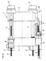
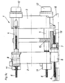
- Fig. 5a to 5d The embodiment of Fig. 5a to 5d is different from that of the Fig. 1 to 4 only by the additional arrangement of a driver 13, which is arranged displaceably between the platens 2, 3.
- a driver 13 which is arranged displaceably between the platens 2, 3.
- either a turntable 14 may be arranged ( Fig. 5a ), on which a center plate 15 can be arranged rotatable about a vertical axis ( Fig. 5b ). But it can also be provided to connect the middle plate 15 rigidly with the driver 13 ( Fig. 5c ).
- the spindle nut 7 is driven via an electric motor 8 which is not designed as a hollow shaft motor or via another drive principle (for example hydraulically).
- the spindle 6 on the one hand rotatably mounted on the fixed platen 3 and on the other hand cooperates with the spindle nut 7, which in turn is rotatably arranged in the driver 13.
- the electric motor 8 drives the spindle, which in this case would have to be rotationally but axially fixedly mounted.
- a turntable 14 which does not allow a rotation about a vertical axis, but about a horizontal axis. Also, it is not absolutely necessary to arrange a middle plate 15 on the turntable 14, but it can rather the driver 13 are supported on the upper side of the platens 2, 3 or on a separate frame, so that a center plate 15 can be mounted on the driver 13 hanging down ,
- the Fig. 6a and 6b show a possibility of cushioned storage of at least one of the spindles 6 (here on the fixed platen 3). Particularly advantageous here is the use of a plurality of disc springs 16, which are cone-shaped.
Landscapes
- Engineering & Computer Science (AREA)
- Manufacturing & Machinery (AREA)
- Mechanical Engineering (AREA)
- Moulds For Moulding Plastics Or The Like (AREA)
- Injection Moulding Of Plastics Or The Like (AREA)
Description
- Die vorliegende Erfindung betrifft eine Schließeinheit für eine Spritzgießmaschine mit den Merkmalen des Oberbegriffs des Anspruchs 1.
- Eine derartige Schließeinheit geht aus der
EP 1 967 348 A1 hervor. Bei der dort gezeigten Schließeinheit wird die Spindelmutter über einen Riementrieb durch einen Elektromotor angetrieben. Nachteilig ist daran der große Platzbedarf. - Aufgabe der Erfindung ist es, eine gattungsgemäße Schließeinheit derart weiterzubilden, dass der Platzbedarf geringer ist.
- Diese Aufgabe wird durch eine Schließeinheit mit den Merkmalen des Anspruchs 1 gelöst.
- Neben der kompakten Bauweise hat die erfindungsgemäße Lösung den weiteren Vorteil, dass die vom Elektromotor erzeugte Antriebskraft zentral auf die Spindelmutter aufgebracht wird.
- Weitere vorteilhafte Ausführungsformen der Erfindung sind in den abhängigen Ansprüchen definiert.
- So kann beispielsweise vorgesehen sein, wenigstens zwei Eilhubvorrichtungen zu verwenden, deren Elektromotoren vorzugsweise an einer der beiden Formaufspannplatten angeordnet sind. Die Anordnung der Elektromotoren der wenigstens zwei Eilhubvorrichtungen kann beispielsweise in einander diagonal gegenüberliegenden Eckbereichen der Formaufspannplatte erfolgen. Alternativ kann vorgesehen sein, dass die Elektromotoren gemeinsam im unteren oder oberen Bereich der Formaufspannplatte angeordnet sind.
- Besonders bevorzugt ist vorgesehen, dass die Schließeinheit als Zweiplatten-Schießeinheit ausgebildet ist, vorzugsweise mit wenigstens zwei Zugholmen, die an der einen Formaufspannplatte gelagert und mit der anderen Formaufspannplatte verriegelbar sind.
- Weiters kann vorgesehen sein, dass zwischen den wenigstens zwei relativ zueinander verfahrbaren Formaufspannplatten ein Mitnehmer angeordnet ist, mit dem starr oder über einen Drehtisch eine Mittelplatte verbunden oder verbindbar ist. Im Falle einer starren Verbindung kann die Mittelplatte auch einstückig mit dem Mitnehmer ausgebildet sein. Zum Verschieben des Mitnehmers relativ zu wenigstens einer der Formaufspannplatten können eine Spindel und eine mit der Spindel im Eingriff stehende Spindelmutter vorgesehen sein. Besonders bevorzugt ist dann vorgesehen, dass ein die Spindelmutter antreibender Elektromotor als Hohlwellenmotor ausgebildet ist. Es ist aber grundsätzlich denkbar, den Mitnehmer über einen nicht als Hohlwellenmotor ausgebildeten Elektromotor oder überhaupt über ein anderes (nicht elektromotorisches) Antriebssystem anzutreiben.
- Zur Abfederung wenigstens einer der Spindeln kann vorgesehen sein, diese über kegelförmige Tellerfedern an der Formaufspannplatte oder dem Mitnehmer abgefedert zu lagern.
- Besonders bevorzugt ist vorgesehen, dass wenigstens eine der Formaufspannplatten von Holmen durchsetzt ist und die Spindel(n) von den Holmen, vorzugsweise von den Zugholmen, gesondert ausgebildet ist bzw. sind.
- Schutz wird auch begehrt für eine Spritzgießmaschine mit einer Schließeinheit nach einer der vorstehend genannten Ausführungsformen.
- Weitere Vorteile und Einzelheiten der Erfindung ergeben sich anhand der Figuren sowie der dazugehörigen Figurenbeschreibung. Dabei zeigen:
- Fig. 1
- eine perspektivische Ansicht eines Ausführungsbeispiels einer erfindungsgemäßen Schließeinheit,
- Fig. 2
- eine Draufsicht auf die bewegbare Formaufspannplatte der in
Fig. 1 dargestellten Schließeinheit, - Fig. 3
- eine Seitenansicht zur
Fig. 1 , wobei für die Erfindung unwesentliche Elemente weggelassen wurden, - Fig. 4
- eine teilweise Schnittdarstellung entlang der Linie A - A der
Fig. 2 , - Fig. 5a bis 5d
- ein weiteres Ausführungsbeispiel der Erfindung in verschiedenen Ansichten mit einem verschiebbaren Mitnehmer und
- Fig. 6a, 6b
- eine Möglichkeit der gefederten Lagerung wenigstens einer der Spindeln.
-
Fig. 1 zeigt schematisch in perspektivischer Darstellung eine als Zweiplatten-Schließeinheit ausgebildete Schließeinheit 1, bei welcher auf einem Maschinenbett 10 zwei Formaufspannplatten 2,3 angeordnet sind, die relativ zueinander durch zwei Eilhubvorrichtungen 5 verfahren werden können. Im gezeigten Ausführungsbeispiel ist die eine Formaufspannplatte 2 beweglich ausgebildet und kann auf dem Maschinenbett 10 entlang von Führungen bewegt werden. Die andere Formaufspannplatte 3 ist fest mit dem Maschinenbett 10 verbunden. - In diesem Ausführungsbeispiel sind vier Zugholme 4 in der feststehenden Formaufspannplatte 3 gelagert. Wird die bewegbare Formaufspannplatte 2 zur feststehenden Formaufspannplatte 3 hinbewegt, tauchen die Zugholme 4 in entsprechende Öffnungen der bewegbaren Formaufspannplatte 2 ein. Erkennbar sind in
Fig. 1 vier Verriegelungsvorrichtungen 11, die dazu dienen, die Zugholme 4 mit der bewegbaren Formaufspannplatte 2 zu verriegeln, wenn sich die an den Formaufspannplatten 2, 3 aufgespannten Formhälften (in den Figuren nicht dargestellt) berühren. Anschließend erfolgt in an sich bekannter Weise der Schließkraftaufbau durch vier Druckkissen 12, von denen inFig. 1 zwei erkennbar sind. - Nach Beendigung des Einspritzvorgangs und dem Erstarren des bzw. der gespritzten Formteile, können die Formhälften nach Entlastung der Druckkissen 12 und erfolgter Entriegelung der Zughofme 4 durch die Eilhubvorrichtungen 5 geöffnet werden.
- Wie aus
Fig. 1 hervorgeht, sind in diesem Ausführungsbeispiel die Elektromotoren 8 der Eilhubvorrichtungen 5 fest mit der bewegbaren Formaufspannplatte 2 verbunden und in deren Eckbereichen gelagert. Die Elektromotoren 8, welche erfindungsgemäß als Hohlwellenmotoren ausgebildet sind, treiben Spindelmuttern 7 an. Die entsprechenden Spindeln 6 sind fest mit der feststehenden Formaufspannplatte 3 verbunden. Durch eine Rotation der Spindelmuttern 7 auf den Spindeln 6 ergibt sich die Antriebskraft für die Verschiebung der bewegbaren Formaufspannplatte 2. - Die Anordnung der Elektromotoren 8 der Eilhubvorrichtungen 5 geht auch aus den
Fig. 2 und3 hervor. - Von besonderem Interesse ist noch die
Fig. 4 , welche eine teilweise Schnittdarstellung entlang der Linie A - A derFig. 2 zeigt. Erkennbar ist hier die Ausbildung des Elektromotors 8 als Hohlwellenmotor, wobei die Hohlwelle 9 drehfest mit der Spindelmutter 7 verbunden ist. Erkennbar ist auch, dass die Spindel 6 über Bolzen fest mit der feststehenden Formaufspannplatte 3 verbunden ist. - Das Ausführungsbeispiel der
Fig. 5a bis 5d unterscheidet sich von jenem derFig. 1 bis 4 nur durch die zusätzliche Anordnung eines Mitnehmers 13, welcher zwischen den Formaufspannplatten 2, 3 verschiebbar angeordnet ist. Am Mitnehmer 13 kann entweder ein Drehteller 14 angeordnet sein (Fig. 5a ), auf welchem eine Mittelplatte 15 um eine vertikale Achse drehbar anordenbar ist (Fig. 5b ). Es kann aber auch vorgesehen sein, die Mittelplatte 15 starr mit dem Mitnehmer 13 zu verbinden (Fig. 5c ). - In allen Fällen kann vorgesehen sein, dass zum Verschieben des Mitnehmer 13 eine Eilhubvorrichtung mit einer Spindel 6 und einer durch einen Hohlwellenmotor antreibbaren Spindelmutter 7 zum Einsatz kommt und zwar in der gleichen Form wie bei den Eilhubvorrichtungen 5 für die bewegbare Formaufspannplatte 2. Dieser Fall ist in den
Fig. 5a bis 5d dargestellt. - Alternativ könnte aber auch vorgesehen sein, dass die Spindelmutter 7 über einen nicht als Hohlwellenmotor ausgebildeten Elektromotor 8 oder über ein anderes Antriebsprinzip (zum Beispiel hydraulisch) angetrieben wird.
- In den
Fig. 5a bis 5d ist die Spindel 6 einerseits drehfest an der feststehenden Formaufspannplatte 3 gelagert und wirkt andererseits mit der Spindelmutter 7 zusammen, welche ihrerseits drehbar im Mitnehmer 13 angeordnet ist. Andere Anordnungsmöglichkeiten sind denkbar. Zum Beispiel kann auch vorgesehen sein, dass der Elektromotor 8 die Spindel antreibt, welche in diesem Fall drehend, aber axial feststehend gelagert sein müsste. - Selbstverständlich ist es auch denkbar, dass ein Drehteller 14 vorgesehen ist, welcher einer Drehung nicht um eine vertikale Achse, sondern um eine horizontale Achse gestattet. Auch ist es nicht unbedingt erforderlich, eine Mittelplatte 15 auf dem Drehteller 14 anzuordnen, sondern es kann vielmehr der Mitnehmer 13 an der Oberseite der Formaufspannplatten 2, 3 oder an einem gesonderten Rahmen abgestützt sein, sodass eine Mittelplatte 15 am Mitnehmer 13 herabhängend gelagert werden kann.
- Die
Fig. 6a und6b zeigen eine Möglichkeit der abgefederten Lagerung wenigstens einer der Spindeln 6 (hier an der feststehenden Formaufspannplatte 3). Besonders vorteilhaft ist hier die Verwendung mehrerer Tellerfedern 16, welche kegelförmig ausgebildet sind.
Claims (10)
- Zweiplatten-Schließeinheit (1) für eine Spritzgießmaschine, mit:- einem Maschinenbett (10),- zwei relativ zueinander verfahrbaren Formaufspannplatten (2, 3), von denen die eine Formaufspannplatte (2) entlang von Führungen auf dem Maschinenbett (10) verschiebbar ist und die andere Formaufspannplatte (3) fest mit dem Maschinenbett verbunden ist,- wenigstens einer Eilhubvorrichtung (5) zum Verfahren der Formaufspannplatten (2, 3) relativ zueinander, die eine drehfest mit der einen Formaufspannplatte (3) verbundene Spindel (6) und eine mit der Spindel (6) im Eingriff stehende und drehbar mit der anderen Formaufspannplatte (2) verbundene Spindelmutter (7) aufweist,- einem als Hohlwellenmotor ausgebildeten Elektromotor (8) zum Antreiben der Spindelmutter (7), wobei die Spindel (6) abschnittsweise in der Hohlwelle (8) verläuft,- Holmen, die wenigstens eine der Formaufspannplatten (2, 3) durchsetzen, wobei die Spindel (6) von den Holmen gesondert ausgebildet ist,dadurch gekennzeichnet, dass die Spindel (6) drehfest mit der fest mit dem Maschinenbett (10) verbundenen Formaufspannplatte (3) verbunden ist.
- Schließeinheit nach Anspruch 1, dadurch gekennzeichnet, dass wenigstens zwei Eilhubvorrichtungen (5) vorgesehen sind, deren Elektromotoren (8) vorzugsweise an einer der beiden Formaufspannplatten (2, 3) angeordnet sind.
- Schließeinheit nach Anspruch 2, dadurch gekennzeichnet, dass die Elektromotoren (8) der wenigstens zwei Eilhubvorrichtungen (5) in einander diagonal gegenüber liegenden Eckbereichen der Formaufspannplatte (2, 3) angeordnet sind.
- Schließeinheit nach Anspruch 2, dadurch gekennzeichnet, dass die Elektromotoren (8) der wenigstens zwei Eilhubvorrichtungen (5) gemeinsam im unteren oder oberen Bereich der Formaufspannplatte (2, 3) angeordnet sind.
- Schließeinheit nach einem der Ansprüche 1 bis 4, dadurch gekennzeichnet, dass wenigstens zwei Zugholme (4) vorgesehen sind, die an der einen Formaufspannplatte (3) gelagert und mit der anderen Formaufspannplatte (2) verriegelbar sind.
- Schließeinheit nach einem der Ansprüche 1 bis 4, dadurch gekennzeichnet, dass zwischen den zwei relativ zueinander verfahrbaren Formaufspannplatten (2, 3) ein Mitnehmer (13) angeordnet ist, mit dem eine Mittelplatte (15) starr oder über einen Drehtisch (14) verbunden oder verbindbar ist.
- Schließeinheit nach Anspruch 6, dadurch gekennzeichnet, dass der Mitnehmer (13) über eine Spindel (6) und eine mit der Spindel (6) im Eingriff stehende Spindelmutter (7) relativ zu wenigstens einer der Formaufspannplatten (2, 3) verschiebbar ist.
- Schließeinheit nach Anspruch 7, dadurch gekennzeichnet, dass ein die Spindelmutter (7) antreibender Elektromotor (8) vorgesehen ist, welcher als Hohlwellenmotor ausgebildet ist.
- Schließeinheit nach einem der Ansprüche 1 bis 8, dadurch gekennzeichnet, dass wenigstens eine der Spindeln (6) über Tellerfedern (16) an der Formaufspannplatte (3) oder dem Mitnehmer (13) gelagert ist.
- Spritzgießmaschine mit einer Schließeinheit (1) nach einem der Ansprüche 1 bis 9.
Applications Claiming Priority (1)
| Application Number | Priority Date | Filing Date | Title |
|---|---|---|---|
| AT19592008A AT507717A1 (de) | 2008-12-16 | 2008-12-16 | Schliesseinheit für eine spritzgiessmaschine |
Publications (2)
| Publication Number | Publication Date |
|---|---|
| EP2199056A1 EP2199056A1 (de) | 2010-06-23 |
| EP2199056B1 true EP2199056B1 (de) | 2015-06-17 |
Family
ID=42027680
Family Applications (1)
| Application Number | Title | Priority Date | Filing Date |
|---|---|---|---|
| EP09015303.2A Active EP2199056B1 (de) | 2008-12-16 | 2009-12-10 | Schließeinheit für eine Spritzgießmaschine |
Country Status (3)
| Country | Link |
|---|---|
| EP (1) | EP2199056B1 (de) |
| CN (1) | CN101746025A (de) |
| AT (2) | AT507717A1 (de) |
Families Citing this family (9)
| Publication number | Priority date | Publication date | Assignee | Title |
|---|---|---|---|---|
| AT12819U1 (de) | 2011-01-19 | 2012-12-15 | Engel Austria Gmbh | Vertikale zwei-platten-schliesseinheit |
| DE102011103609A1 (de) | 2011-06-07 | 2012-12-13 | Kraussmaffei Technologies Gmbh | Horizontalspritzgießmaschine mit einem elektromotorisch angetriebenen Schiebetisch |
| WO2013114551A1 (ja) * | 2012-01-31 | 2013-08-08 | 三菱重工プラスチックテクノロジー株式会社 | 型締装置及び射出成形機 |
| JP6727838B2 (ja) * | 2015-02-18 | 2020-07-22 | 芝浦機械株式会社 | 可動盤、開閉装置および成形装置 |
| AT517261B1 (de) * | 2015-05-21 | 2017-05-15 | Engel Austria Gmbh | Vertikale Schließeinheit für eine Formgebungsmaschine |
| AT518464B1 (de) * | 2016-04-08 | 2017-11-15 | Engel Austria Gmbh | Schließeinheit für eine Formgebungsmaschine |
| CN106182590B (zh) * | 2016-08-31 | 2019-03-08 | 惠州市阳鑫塑胶机械有限公司 | 一种双板双色注塑机 |
| AT525237B1 (de) * | 2021-08-13 | 2023-02-15 | Engel Austria Gmbh | Verriegelungsvorrichtung |
| AT526837B1 (de) * | 2023-03-13 | 2024-08-15 | Engel Austria Gmbh | Zwei-Platten-Schließeinheit für eine Formgebungsmaschine |
Citations (7)
| Publication number | Priority date | Publication date | Assignee | Title |
|---|---|---|---|---|
| EP1005971A1 (de) | 1998-12-02 | 2000-06-07 | MANNESMANN Aktiengesellschaft | Schliesseinheit für eine Spritzgiessmachine |
| EP0679492B1 (de) | 1994-04-25 | 2000-06-14 | Husky Injection Molding Systems Ltd. | Kombinierte Formträger und Gestängevorrichtung |
| DE10230024C1 (de) | 2002-07-04 | 2003-10-16 | Demag Ergotech Gmbh | Schließmechanismus für eine Spritzgießmaschine |
| DE10316199A1 (de) | 2002-04-09 | 2003-10-23 | Toshiba Machine Co Ltd | Verfahren und Vorrichtung zum Formschließen bei einer Spritzgießmaschine oder dergleichen |
| DE102006016200A1 (de) | 2006-04-06 | 2007-10-11 | Krauss-Maffei Kunststofftechnik Gmbh | Verfahren und Vorrichtung zur Herstellung von mehrkomponentigen Kunststoff-Formteilen |
| WO2007134428A1 (en) | 2006-05-23 | 2007-11-29 | Husky Injection Molding Systems Ltd. | Molding-system platen actuator |
| JP2008080670A (ja) | 2006-09-28 | 2008-04-10 | Mitsubishi Heavy Industries Plastic Technology Co Ltd | 二材成形用射出成形機及び制御方法 |
Family Cites Families (4)
| Publication number | Priority date | Publication date | Assignee | Title |
|---|---|---|---|---|
| JPH07329135A (ja) * | 1994-06-10 | 1995-12-19 | Ube Ind Ltd | 成形装置の型締装置 |
| JP4684675B2 (ja) * | 2005-02-15 | 2011-05-18 | 東芝機械株式会社 | 型締装置 |
| DE102006016343B4 (de) * | 2006-04-05 | 2009-08-20 | Sumitomo (Shi) Demag Plastics Machinery Gmbh | Schließeinheit für eine Spritzgießmaschine |
| DE102007011443A1 (de) | 2007-03-08 | 2008-09-11 | Robert Bosch Gmbh | Schließeinheit für ein Werkzeug |
-
2008
- 2008-12-16 AT AT19592008A patent/AT507717A1/de active IP Right Grant
-
2009
- 2009-12-10 EP EP09015303.2A patent/EP2199056B1/de active Active
- 2009-12-16 CN CN200910253454A patent/CN101746025A/zh active Pending
-
2011
- 2011-03-25 AT AT0802511U patent/AT12212U1/de not_active IP Right Cessation
Patent Citations (7)
| Publication number | Priority date | Publication date | Assignee | Title |
|---|---|---|---|---|
| EP0679492B1 (de) | 1994-04-25 | 2000-06-14 | Husky Injection Molding Systems Ltd. | Kombinierte Formträger und Gestängevorrichtung |
| EP1005971A1 (de) | 1998-12-02 | 2000-06-07 | MANNESMANN Aktiengesellschaft | Schliesseinheit für eine Spritzgiessmachine |
| DE10316199A1 (de) | 2002-04-09 | 2003-10-23 | Toshiba Machine Co Ltd | Verfahren und Vorrichtung zum Formschließen bei einer Spritzgießmaschine oder dergleichen |
| DE10230024C1 (de) | 2002-07-04 | 2003-10-16 | Demag Ergotech Gmbh | Schließmechanismus für eine Spritzgießmaschine |
| DE102006016200A1 (de) | 2006-04-06 | 2007-10-11 | Krauss-Maffei Kunststofftechnik Gmbh | Verfahren und Vorrichtung zur Herstellung von mehrkomponentigen Kunststoff-Formteilen |
| WO2007134428A1 (en) | 2006-05-23 | 2007-11-29 | Husky Injection Molding Systems Ltd. | Molding-system platen actuator |
| JP2008080670A (ja) | 2006-09-28 | 2008-04-10 | Mitsubishi Heavy Industries Plastic Technology Co Ltd | 二材成形用射出成形機及び制御方法 |
Non-Patent Citations (5)
| Title |
|---|
| "IPF2008 Mitsubishi Heavy Industry", MITSUBISHI_NEWS_2008, 15 March 2016 (2016-03-15), XP055264568 |
| "Mistusbishi emR series 1450/3000", MITSUBISHI HEAVY INDUSTRY PLATECH, pages 1 - 6 |
| "Mitsubishi_History_2008", MITSUBISHI HEAVY INDUSTRY, 15 March 2016 (2016-03-15), pages 1 - 2, XP055264560 |
| MITSUBISHI-PROSPEKT AUF JAPAN INTERNATIONAL PLASTIC FAIR, November 2008 (2008-11-01), XP055266120 |
| MITSUBISHI-WERBUNG AUF JAPAN INTERNATIONAL PLASTIC. FAIR, November 2008 (2008-11-01), XP055266120 |
Also Published As
| Publication number | Publication date |
|---|---|
| AT507717A1 (de) | 2010-07-15 |
| EP2199056A1 (de) | 2010-06-23 |
| CN101746025A (zh) | 2010-06-23 |
| AT12212U1 (de) | 2012-01-15 |
Similar Documents
| Publication | Publication Date | Title |
|---|---|---|
| EP2199056A1 (de) | Schließeinheit für eine Spritzgießmaschine | |
| EP1306185B1 (de) | Dreheinrichtung für Horizontal-Spritzgiessmaschinen | |
| EP1484153A2 (de) | Horizontalspritzgiessmaschine | |
| EP2969461B1 (de) | Haltevorrichtung für wendesystem | |
| WO2011009734A2 (de) | Schliesseinheit für eine spritzgiessmaschine | |
| DE19731833C1 (de) | Spritzgießeinheit für eine Spritzgießmaschine | |
| EP1389160B1 (de) | Formaufspannplatte für eine spritzgiessmaschine, sowie eine zwei-platten-spritzgiessmaschine hiermit | |
| EP1340607B1 (de) | Mehrkomponenten-Spritzgiessmaschine mit variabler Positionierung der sekundären Einspritzeinheit | |
| EP3036077A1 (de) | Mehrkomponenten-spritzgiessmaschine mit drehbarem mittelteil | |
| EP1802441B1 (de) | Schliesseinheit für eine spritzgiessmaschine mit etagenwerkzeug | |
| WO1995008428A1 (de) | Zweifach-schliesseinheit einer spritzgiessmaschine | |
| DE102008023720B3 (de) | Formschließeinheit einer Spritzgießmaschine | |
| EP1512512B1 (de) | Spritzgiessvorrichtung | |
| EP1277557A1 (de) | Spritzgiessmaschine | |
| DE102024136234B3 (de) | Formschließeinheit | |
| EP1848577B1 (de) | Spritzgiessmaschine zur verarbeitung von kunststoffen | |
| DE102017106179A1 (de) | Etagenwerkzeug | |
| DE102004024731B4 (de) | Spritzgießvorrichtung | |
| DE4323395C2 (de) | Schließeinheit für eine Kunststoff-Spritzgießmaschine | |
| EP1784295B1 (de) | Spritzgiessmaschine | |
| DE102016119847A1 (de) | Mehrspindelauswerfer mit Überlastsicherung | |
| DE10004247A1 (de) | Vorrichtung zur Herstellung von geblasenen Hohlkörpern aus Kunststoff | |
| AT523448A1 (de) | Einspritzeinheit für eine Formgebungsmaschine und Formgebungsmaschine mit einer solchen | |
| AT7472U1 (de) | Spritzgiessmaschine | |
| AT17168U1 (de) | Einspritzeinheit für eine Formgebungsmaschine und Formgebungsmaschine mit einer solchen |
Legal Events
| Date | Code | Title | Description |
|---|---|---|---|
| PUAI | Public reference made under article 153(3) epc to a published international application that has entered the european phase |
Free format text: ORIGINAL CODE: 0009012 |
|
| AK | Designated contracting states |
Kind code of ref document: A1 Designated state(s): AT BE BG CH CY CZ DE DK EE ES FI FR GB GR HR HU IE IS IT LI LT LU LV MC MK MT NL NO PL PT RO SE SI SK SM TR |
|
| AX | Request for extension of the european patent |
Extension state: AL BA RS |
|
| 17P | Request for examination filed |
Effective date: 20101007 |
|
| GRAP | Despatch of communication of intention to grant a patent |
Free format text: ORIGINAL CODE: EPIDOSNIGR1 |
|
| INTG | Intention to grant announced |
Effective date: 20150316 |
|
| GRAS | Grant fee paid |
Free format text: ORIGINAL CODE: EPIDOSNIGR3 |
|
| GRAA | (expected) grant |
Free format text: ORIGINAL CODE: 0009210 |
|
| AK | Designated contracting states |
Kind code of ref document: B1 Designated state(s): AT BE BG CH CY CZ DE DK EE ES FI FR GB GR HR HU IE IS IT LI LT LU LV MC MK MT NL NO PL PT RO SE SI SK SM TR |
|
| REG | Reference to a national code |
Ref country code: GB Ref legal event code: FG4D Free format text: NOT ENGLISH |
|
| REG | Reference to a national code |
Ref country code: CH Ref legal event code: EP |
|
| REG | Reference to a national code |
Ref country code: AT Ref legal event code: REF Ref document number: 731656 Country of ref document: AT Kind code of ref document: T Effective date: 20150715 |
|
| REG | Reference to a national code |
Ref country code: DE Ref legal event code: R096 Ref document number: 502009011150 Country of ref document: DE |
|
| REG | Reference to a national code |
Ref country code: IE Ref legal event code: FG4D Free format text: LANGUAGE OF EP DOCUMENT: GERMAN |
|
| PG25 | Lapsed in a contracting state [announced via postgrant information from national office to epo] |
Ref country code: LT Free format text: LAPSE BECAUSE OF FAILURE TO SUBMIT A TRANSLATION OF THE DESCRIPTION OR TO PAY THE FEE WITHIN THE PRESCRIBED TIME-LIMIT Effective date: 20150617 Ref country code: FI Free format text: LAPSE BECAUSE OF FAILURE TO SUBMIT A TRANSLATION OF THE DESCRIPTION OR TO PAY THE FEE WITHIN THE PRESCRIBED TIME-LIMIT Effective date: 20150617 Ref country code: HR Free format text: LAPSE BECAUSE OF FAILURE TO SUBMIT A TRANSLATION OF THE DESCRIPTION OR TO PAY THE FEE WITHIN THE PRESCRIBED TIME-LIMIT Effective date: 20150617 Ref country code: NO Free format text: LAPSE BECAUSE OF FAILURE TO SUBMIT A TRANSLATION OF THE DESCRIPTION OR TO PAY THE FEE WITHIN THE PRESCRIBED TIME-LIMIT Effective date: 20150917 |
|
| REG | Reference to a national code |
Ref country code: LT Ref legal event code: MG4D Ref country code: NL Ref legal event code: MP Effective date: 20150617 |
|
| PG25 | Lapsed in a contracting state [announced via postgrant information from national office to epo] |
Ref country code: GR Free format text: LAPSE BECAUSE OF FAILURE TO SUBMIT A TRANSLATION OF THE DESCRIPTION OR TO PAY THE FEE WITHIN THE PRESCRIBED TIME-LIMIT Effective date: 20150918 Ref country code: BG Free format text: LAPSE BECAUSE OF FAILURE TO SUBMIT A TRANSLATION OF THE DESCRIPTION OR TO PAY THE FEE WITHIN THE PRESCRIBED TIME-LIMIT Effective date: 20150917 Ref country code: LV Free format text: LAPSE BECAUSE OF FAILURE TO SUBMIT A TRANSLATION OF THE DESCRIPTION OR TO PAY THE FEE WITHIN THE PRESCRIBED TIME-LIMIT Effective date: 20150617 |
|
| PG25 | Lapsed in a contracting state [announced via postgrant information from national office to epo] |
Ref country code: EE Free format text: LAPSE BECAUSE OF FAILURE TO SUBMIT A TRANSLATION OF THE DESCRIPTION OR TO PAY THE FEE WITHIN THE PRESCRIBED TIME-LIMIT Effective date: 20150617 |
|
| PG25 | Lapsed in a contracting state [announced via postgrant information from national office to epo] |
Ref country code: SK Free format text: LAPSE BECAUSE OF FAILURE TO SUBMIT A TRANSLATION OF THE DESCRIPTION OR TO PAY THE FEE WITHIN THE PRESCRIBED TIME-LIMIT Effective date: 20150617 Ref country code: PT Free format text: LAPSE BECAUSE OF FAILURE TO SUBMIT A TRANSLATION OF THE DESCRIPTION OR TO PAY THE FEE WITHIN THE PRESCRIBED TIME-LIMIT Effective date: 20151019 Ref country code: PL Free format text: LAPSE BECAUSE OF FAILURE TO SUBMIT A TRANSLATION OF THE DESCRIPTION OR TO PAY THE FEE WITHIN THE PRESCRIBED TIME-LIMIT Effective date: 20150617 Ref country code: RO Free format text: LAPSE BECAUSE OF NON-PAYMENT OF DUE FEES Effective date: 20150617 Ref country code: IS Free format text: LAPSE BECAUSE OF FAILURE TO SUBMIT A TRANSLATION OF THE DESCRIPTION OR TO PAY THE FEE WITHIN THE PRESCRIBED TIME-LIMIT Effective date: 20151017 Ref country code: ES Free format text: LAPSE BECAUSE OF FAILURE TO SUBMIT A TRANSLATION OF THE DESCRIPTION OR TO PAY THE FEE WITHIN THE PRESCRIBED TIME-LIMIT Effective date: 20150617 Ref country code: CZ Free format text: LAPSE BECAUSE OF FAILURE TO SUBMIT A TRANSLATION OF THE DESCRIPTION OR TO PAY THE FEE WITHIN THE PRESCRIBED TIME-LIMIT Effective date: 20150617 |
|
| REG | Reference to a national code |
Ref country code: DE Ref legal event code: R026 Ref document number: 502009011150 Country of ref document: DE |
|
| PLBI | Opposition filed |
Free format text: ORIGINAL CODE: 0009260 |
|
| 26 | Opposition filed |
Opponent name: KRAUSSMAFFEI TECHNOLOGIES GMBH Effective date: 20160317 |
|
| PLAX | Notice of opposition and request to file observation + time limit sent |
Free format text: ORIGINAL CODE: EPIDOSNOBS2 |
|
| PG25 | Lapsed in a contracting state [announced via postgrant information from national office to epo] |
Ref country code: DK Free format text: LAPSE BECAUSE OF FAILURE TO SUBMIT A TRANSLATION OF THE DESCRIPTION OR TO PAY THE FEE WITHIN THE PRESCRIBED TIME-LIMIT Effective date: 20150617 |
|
| PG25 | Lapsed in a contracting state [announced via postgrant information from national office to epo] |
Ref country code: BE Free format text: LAPSE BECAUSE OF NON-PAYMENT OF DUE FEES Effective date: 20151231 |
|
| PLBB | Reply of patent proprietor to notice(s) of opposition received |
Free format text: ORIGINAL CODE: EPIDOSNOBS3 |
|
| PG25 | Lapsed in a contracting state [announced via postgrant information from national office to epo] |
Ref country code: LU Free format text: LAPSE BECAUSE OF FAILURE TO SUBMIT A TRANSLATION OF THE DESCRIPTION OR TO PAY THE FEE WITHIN THE PRESCRIBED TIME-LIMIT Effective date: 20151210 Ref country code: MC Free format text: LAPSE BECAUSE OF FAILURE TO SUBMIT A TRANSLATION OF THE DESCRIPTION OR TO PAY THE FEE WITHIN THE PRESCRIBED TIME-LIMIT Effective date: 20150617 |
|
| REG | Reference to a national code |
Ref country code: CH Ref legal event code: PL |
|
| GBPC | Gb: european patent ceased through non-payment of renewal fee |
Effective date: 20151210 |
|
| PG25 | Lapsed in a contracting state [announced via postgrant information from national office to epo] |
Ref country code: SI Free format text: LAPSE BECAUSE OF FAILURE TO SUBMIT A TRANSLATION OF THE DESCRIPTION OR TO PAY THE FEE WITHIN THE PRESCRIBED TIME-LIMIT Effective date: 20150617 |
|
| REG | Reference to a national code |
Ref country code: IE Ref legal event code: MM4A |
|
| REG | Reference to a national code |
Ref country code: FR Ref legal event code: ST Effective date: 20160831 |
|
| PG25 | Lapsed in a contracting state [announced via postgrant information from national office to epo] |
Ref country code: LI Free format text: LAPSE BECAUSE OF NON-PAYMENT OF DUE FEES Effective date: 20151231 Ref country code: IE Free format text: LAPSE BECAUSE OF NON-PAYMENT OF DUE FEES Effective date: 20151210 Ref country code: CH Free format text: LAPSE BECAUSE OF NON-PAYMENT OF DUE FEES Effective date: 20151231 Ref country code: GB Free format text: LAPSE BECAUSE OF NON-PAYMENT OF DUE FEES Effective date: 20151210 |
|
| PG25 | Lapsed in a contracting state [announced via postgrant information from national office to epo] |
Ref country code: FR Free format text: LAPSE BECAUSE OF NON-PAYMENT OF DUE FEES Effective date: 20151231 |
|
| REG | Reference to a national code |
Ref country code: DE Ref legal event code: R100 Ref document number: 502009011150 Country of ref document: DE |
|
| PG25 | Lapsed in a contracting state [announced via postgrant information from national office to epo] |
Ref country code: SM Free format text: LAPSE BECAUSE OF FAILURE TO SUBMIT A TRANSLATION OF THE DESCRIPTION OR TO PAY THE FEE WITHIN THE PRESCRIBED TIME-LIMIT Effective date: 20150617 Ref country code: HU Free format text: LAPSE BECAUSE OF FAILURE TO SUBMIT A TRANSLATION OF THE DESCRIPTION OR TO PAY THE FEE WITHIN THE PRESCRIBED TIME-LIMIT; INVALID AB INITIO Effective date: 20091210 |
|
| PLCK | Communication despatched that opposition was rejected |
Free format text: ORIGINAL CODE: EPIDOSNREJ1 |
|
| STAA | Information on the status of an ep patent application or granted ep patent |
Free format text: STATUS: THE PATENT HAS BEEN GRANTED |
|
| PG25 | Lapsed in a contracting state [announced via postgrant information from national office to epo] |
Ref country code: SE Free format text: LAPSE BECAUSE OF FAILURE TO SUBMIT A TRANSLATION OF THE DESCRIPTION OR TO PAY THE FEE WITHIN THE PRESCRIBED TIME-LIMIT Effective date: 20150617 Ref country code: NL Free format text: LAPSE BECAUSE OF FAILURE TO SUBMIT A TRANSLATION OF THE DESCRIPTION OR TO PAY THE FEE WITHIN THE PRESCRIBED TIME-LIMIT Effective date: 20150617 Ref country code: CY Free format text: LAPSE BECAUSE OF FAILURE TO SUBMIT A TRANSLATION OF THE DESCRIPTION OR TO PAY THE FEE WITHIN THE PRESCRIBED TIME-LIMIT Effective date: 20150617 |
|
| PG25 | Lapsed in a contracting state [announced via postgrant information from national office to epo] |
Ref country code: MT Free format text: LAPSE BECAUSE OF FAILURE TO SUBMIT A TRANSLATION OF THE DESCRIPTION OR TO PAY THE FEE WITHIN THE PRESCRIBED TIME-LIMIT Effective date: 20150617 Ref country code: TR Free format text: LAPSE BECAUSE OF FAILURE TO SUBMIT A TRANSLATION OF THE DESCRIPTION OR TO PAY THE FEE WITHIN THE PRESCRIBED TIME-LIMIT Effective date: 20150617 |
|
| PLBN | Opposition rejected |
Free format text: ORIGINAL CODE: 0009273 |
|
| STAA | Information on the status of an ep patent application or granted ep patent |
Free format text: STATUS: OPPOSITION REJECTED |
|
| 27O | Opposition rejected |
Effective date: 20170530 |
|
| PG25 | Lapsed in a contracting state [announced via postgrant information from national office to epo] |
Ref country code: MK Free format text: LAPSE BECAUSE OF FAILURE TO SUBMIT A TRANSLATION OF THE DESCRIPTION OR TO PAY THE FEE WITHIN THE PRESCRIBED TIME-LIMIT Effective date: 20150617 |
|
| PGFP | Annual fee paid to national office [announced via postgrant information from national office to epo] |
Ref country code: IT Payment date: 20211220 Year of fee payment: 13 |
|
| PG25 | Lapsed in a contracting state [announced via postgrant information from national office to epo] |
Ref country code: IT Free format text: LAPSE BECAUSE OF NON-PAYMENT OF DUE FEES Effective date: 20221210 |
|
| PGFP | Annual fee paid to national office [announced via postgrant information from national office to epo] |
Ref country code: AT Payment date: 20241223 Year of fee payment: 16 |
|
| PGFP | Annual fee paid to national office [announced via postgrant information from national office to epo] |
Ref country code: DE Payment date: 20251229 Year of fee payment: 17 |