EP2199064A1 - Geformter verbundartikel und verfahren zu seiner herstellung - Google Patents
Geformter verbundartikel und verfahren zu seiner herstellung Download PDFInfo
- Publication number
- EP2199064A1 EP2199064A1 EP08830434A EP08830434A EP2199064A1 EP 2199064 A1 EP2199064 A1 EP 2199064A1 EP 08830434 A EP08830434 A EP 08830434A EP 08830434 A EP08830434 A EP 08830434A EP 2199064 A1 EP2199064 A1 EP 2199064A1
- Authority
- EP
- European Patent Office
- Prior art keywords
- resin
- layer base
- composite article
- molded composite
- surface layer
- Prior art date
- Legal status (The legal status is an assumption and is not a legal conclusion. Google has not performed a legal analysis and makes no representation as to the accuracy of the status listed.)
- Granted
Links
Images


Classifications
-
- B—PERFORMING OPERATIONS; TRANSPORTING
- B32—LAYERED PRODUCTS
- B32B—LAYERED PRODUCTS, i.e. PRODUCTS BUILT-UP OF STRATA OF FLAT OR NON-FLAT, e.g. CELLULAR OR HONEYCOMB, FORM
- B32B3/00—Layered products comprising a layer with external or internal discontinuities or unevennesses, or a layer of non-planar shape; Layered products comprising a layer having particular features of form
- B32B3/02—Layered products comprising a layer with external or internal discontinuities or unevennesses, or a layer of non-planar shape; Layered products comprising a layer having particular features of form characterised by features of form at particular places, e.g. in edge regions
-
- B—PERFORMING OPERATIONS; TRANSPORTING
- B29—WORKING OF PLASTICS; WORKING OF SUBSTANCES IN A PLASTIC STATE IN GENERAL
- B29C—SHAPING OR JOINING OF PLASTICS; SHAPING OF MATERIAL IN A PLASTIC STATE, NOT OTHERWISE PROVIDED FOR; AFTER-TREATMENT OF THE SHAPED PRODUCTS, e.g. REPAIRING
- B29C45/00—Injection moulding, i.e. forcing the required volume of moulding material through a nozzle into a closed mould; Apparatus therefor
- B29C45/14—Injection moulding, i.e. forcing the required volume of moulding material through a nozzle into a closed mould; Apparatus therefor incorporating preformed parts or layers, e.g. injection moulding around inserts or for coating articles
- B29C45/14311—Injection moulding, i.e. forcing the required volume of moulding material through a nozzle into a closed mould; Apparatus therefor incorporating preformed parts or layers, e.g. injection moulding around inserts or for coating articles using means for bonding the coating to the articles
-
- B—PERFORMING OPERATIONS; TRANSPORTING
- B29—WORKING OF PLASTICS; WORKING OF SUBSTANCES IN A PLASTIC STATE IN GENERAL
- B29C—SHAPING OR JOINING OF PLASTICS; SHAPING OF MATERIAL IN A PLASTIC STATE, NOT OTHERWISE PROVIDED FOR; AFTER-TREATMENT OF THE SHAPED PRODUCTS, e.g. REPAIRING
- B29C45/00—Injection moulding, i.e. forcing the required volume of moulding material through a nozzle into a closed mould; Apparatus therefor
- B29C45/14—Injection moulding, i.e. forcing the required volume of moulding material through a nozzle into a closed mould; Apparatus therefor incorporating preformed parts or layers, e.g. injection moulding around inserts or for coating articles
- B29C45/14778—Injection moulding, i.e. forcing the required volume of moulding material through a nozzle into a closed mould; Apparatus therefor incorporating preformed parts or layers, e.g. injection moulding around inserts or for coating articles the article consisting of a material with particular properties, e.g. porous, brittle
- B29C45/14811—Multilayered articles
-
- B—PERFORMING OPERATIONS; TRANSPORTING
- B32—LAYERED PRODUCTS
- B32B—LAYERED PRODUCTS, i.e. PRODUCTS BUILT-UP OF STRATA OF FLAT OR NON-FLAT, e.g. CELLULAR OR HONEYCOMB, FORM
- B32B27/00—Layered products comprising a layer of synthetic resin
- B32B27/06—Layered products comprising a layer of synthetic resin as the main or only constituent of a layer, which is next to another layer of the same or of a different material
- B32B27/065—Layered products comprising a layer of synthetic resin as the main or only constituent of a layer, which is next to another layer of the same or of a different material of foam
-
- B—PERFORMING OPERATIONS; TRANSPORTING
- B32—LAYERED PRODUCTS
- B32B—LAYERED PRODUCTS, i.e. PRODUCTS BUILT-UP OF STRATA OF FLAT OR NON-FLAT, e.g. CELLULAR OR HONEYCOMB, FORM
- B32B27/00—Layered products comprising a layer of synthetic resin
- B32B27/06—Layered products comprising a layer of synthetic resin as the main or only constituent of a layer, which is next to another layer of the same or of a different material
- B32B27/08—Layered products comprising a layer of synthetic resin as the main or only constituent of a layer, which is next to another layer of the same or of a different material of synthetic resin
-
- B—PERFORMING OPERATIONS; TRANSPORTING
- B32—LAYERED PRODUCTS
- B32B—LAYERED PRODUCTS, i.e. PRODUCTS BUILT-UP OF STRATA OF FLAT OR NON-FLAT, e.g. CELLULAR OR HONEYCOMB, FORM
- B32B27/00—Layered products comprising a layer of synthetic resin
- B32B27/12—Layered products comprising a layer of synthetic resin next to a fibrous or filamentary layer
-
- B—PERFORMING OPERATIONS; TRANSPORTING
- B32—LAYERED PRODUCTS
- B32B—LAYERED PRODUCTS, i.e. PRODUCTS BUILT-UP OF STRATA OF FLAT OR NON-FLAT, e.g. CELLULAR OR HONEYCOMB, FORM
- B32B27/00—Layered products comprising a layer of synthetic resin
- B32B27/18—Layered products comprising a layer of synthetic resin characterised by the use of special additives
- B32B27/20—Layered products comprising a layer of synthetic resin characterised by the use of special additives using fillers, pigments, thixotroping agents
-
- B—PERFORMING OPERATIONS; TRANSPORTING
- B32—LAYERED PRODUCTS
- B32B—LAYERED PRODUCTS, i.e. PRODUCTS BUILT-UP OF STRATA OF FLAT OR NON-FLAT, e.g. CELLULAR OR HONEYCOMB, FORM
- B32B27/00—Layered products comprising a layer of synthetic resin
- B32B27/18—Layered products comprising a layer of synthetic resin characterised by the use of special additives
- B32B27/22—Layered products comprising a layer of synthetic resin characterised by the use of special additives using plasticisers
-
- B—PERFORMING OPERATIONS; TRANSPORTING
- B32—LAYERED PRODUCTS
- B32B—LAYERED PRODUCTS, i.e. PRODUCTS BUILT-UP OF STRATA OF FLAT OR NON-FLAT, e.g. CELLULAR OR HONEYCOMB, FORM
- B32B27/00—Layered products comprising a layer of synthetic resin
- B32B27/28—Layered products comprising a layer of synthetic resin comprising synthetic resins not wholly covered by any one of the sub-groups B32B27/30 - B32B27/42
- B32B27/281—Layered products comprising a layer of synthetic resin comprising synthetic resins not wholly covered by any one of the sub-groups B32B27/30 - B32B27/42 comprising polyimides
-
- B—PERFORMING OPERATIONS; TRANSPORTING
- B32—LAYERED PRODUCTS
- B32B—LAYERED PRODUCTS, i.e. PRODUCTS BUILT-UP OF STRATA OF FLAT OR NON-FLAT, e.g. CELLULAR OR HONEYCOMB, FORM
- B32B27/00—Layered products comprising a layer of synthetic resin
- B32B27/28—Layered products comprising a layer of synthetic resin comprising synthetic resins not wholly covered by any one of the sub-groups B32B27/30 - B32B27/42
- B32B27/285—Layered products comprising a layer of synthetic resin comprising synthetic resins not wholly covered by any one of the sub-groups B32B27/30 - B32B27/42 comprising polyethers
-
- B—PERFORMING OPERATIONS; TRANSPORTING
- B32—LAYERED PRODUCTS
- B32B—LAYERED PRODUCTS, i.e. PRODUCTS BUILT-UP OF STRATA OF FLAT OR NON-FLAT, e.g. CELLULAR OR HONEYCOMB, FORM
- B32B27/00—Layered products comprising a layer of synthetic resin
- B32B27/28—Layered products comprising a layer of synthetic resin comprising synthetic resins not wholly covered by any one of the sub-groups B32B27/30 - B32B27/42
- B32B27/286—Layered products comprising a layer of synthetic resin comprising synthetic resins not wholly covered by any one of the sub-groups B32B27/30 - B32B27/42 comprising polysulphones; polysulfides
-
- B—PERFORMING OPERATIONS; TRANSPORTING
- B32—LAYERED PRODUCTS
- B32B—LAYERED PRODUCTS, i.e. PRODUCTS BUILT-UP OF STRATA OF FLAT OR NON-FLAT, e.g. CELLULAR OR HONEYCOMB, FORM
- B32B27/00—Layered products comprising a layer of synthetic resin
- B32B27/30—Layered products comprising a layer of synthetic resin comprising vinyl (co)polymers; comprising acrylic (co)polymers
-
- B—PERFORMING OPERATIONS; TRANSPORTING
- B32—LAYERED PRODUCTS
- B32B—LAYERED PRODUCTS, i.e. PRODUCTS BUILT-UP OF STRATA OF FLAT OR NON-FLAT, e.g. CELLULAR OR HONEYCOMB, FORM
- B32B27/00—Layered products comprising a layer of synthetic resin
- B32B27/32—Layered products comprising a layer of synthetic resin comprising polyolefins
- B32B27/322—Layered products comprising a layer of synthetic resin comprising polyolefins comprising halogenated polyolefins, e.g. PTFE
-
- B—PERFORMING OPERATIONS; TRANSPORTING
- B32—LAYERED PRODUCTS
- B32B—LAYERED PRODUCTS, i.e. PRODUCTS BUILT-UP OF STRATA OF FLAT OR NON-FLAT, e.g. CELLULAR OR HONEYCOMB, FORM
- B32B27/00—Layered products comprising a layer of synthetic resin
- B32B27/34—Layered products comprising a layer of synthetic resin comprising polyamides
-
- B—PERFORMING OPERATIONS; TRANSPORTING
- B32—LAYERED PRODUCTS
- B32B—LAYERED PRODUCTS, i.e. PRODUCTS BUILT-UP OF STRATA OF FLAT OR NON-FLAT, e.g. CELLULAR OR HONEYCOMB, FORM
- B32B27/00—Layered products comprising a layer of synthetic resin
- B32B27/36—Layered products comprising a layer of synthetic resin comprising polyesters
- B32B27/365—Layered products comprising a layer of synthetic resin comprising polyesters comprising polycarbonates
-
- B—PERFORMING OPERATIONS; TRANSPORTING
- B32—LAYERED PRODUCTS
- B32B—LAYERED PRODUCTS, i.e. PRODUCTS BUILT-UP OF STRATA OF FLAT OR NON-FLAT, e.g. CELLULAR OR HONEYCOMB, FORM
- B32B27/00—Layered products comprising a layer of synthetic resin
- B32B27/38—Layered products comprising a layer of synthetic resin comprising epoxy resins
-
- B—PERFORMING OPERATIONS; TRANSPORTING
- B32—LAYERED PRODUCTS
- B32B—LAYERED PRODUCTS, i.e. PRODUCTS BUILT-UP OF STRATA OF FLAT OR NON-FLAT, e.g. CELLULAR OR HONEYCOMB, FORM
- B32B3/00—Layered products comprising a layer with external or internal discontinuities or unevennesses, or a layer of non-planar shape; Layered products comprising a layer having particular features of form
- B32B3/02—Layered products comprising a layer with external or internal discontinuities or unevennesses, or a layer of non-planar shape; Layered products comprising a layer having particular features of form characterised by features of form at particular places, e.g. in edge regions
- B32B3/06—Layered products comprising a layer with external or internal discontinuities or unevennesses, or a layer of non-planar shape; Layered products comprising a layer having particular features of form characterised by features of form at particular places, e.g. in edge regions for securing layers together; for attaching the product to another member, e.g. to a support, or to another product, e.g. groove/tongue, interlocking
-
- B—PERFORMING OPERATIONS; TRANSPORTING
- B32—LAYERED PRODUCTS
- B32B—LAYERED PRODUCTS, i.e. PRODUCTS BUILT-UP OF STRATA OF FLAT OR NON-FLAT, e.g. CELLULAR OR HONEYCOMB, FORM
- B32B3/00—Layered products comprising a layer with external or internal discontinuities or unevennesses, or a layer of non-planar shape; Layered products comprising a layer having particular features of form
- B32B3/10—Layered products comprising a layer with external or internal discontinuities or unevennesses, or a layer of non-planar shape; Layered products comprising a layer having particular features of form characterised by a discontinuous layer, i.e. formed of separate pieces of material
- B32B3/12—Layered products comprising a layer with external or internal discontinuities or unevennesses, or a layer of non-planar shape; Layered products comprising a layer having particular features of form characterised by a discontinuous layer, i.e. formed of separate pieces of material characterised by a layer of regularly- arranged cells, e.g. a honeycomb structure
-
- B—PERFORMING OPERATIONS; TRANSPORTING
- B32—LAYERED PRODUCTS
- B32B—LAYERED PRODUCTS, i.e. PRODUCTS BUILT-UP OF STRATA OF FLAT OR NON-FLAT, e.g. CELLULAR OR HONEYCOMB, FORM
- B32B5/00—Layered products characterised by the non- homogeneity or physical structure, i.e. comprising a fibrous, filamentary, particulate or foam layer; Layered products characterised by having a layer differing constitutionally or physically in different parts
- B32B5/18—Layered products characterised by the non- homogeneity or physical structure, i.e. comprising a fibrous, filamentary, particulate or foam layer; Layered products characterised by having a layer differing constitutionally or physically in different parts characterised by features of a layer of foamed material
-
- B—PERFORMING OPERATIONS; TRANSPORTING
- B32—LAYERED PRODUCTS
- B32B—LAYERED PRODUCTS, i.e. PRODUCTS BUILT-UP OF STRATA OF FLAT OR NON-FLAT, e.g. CELLULAR OR HONEYCOMB, FORM
- B32B7/00—Layered products characterised by the relation between layers; Layered products characterised by the relative orientation of features between layers, or by the relative values of a measurable parameter between layers, i.e. products comprising layers having different physical, chemical or physicochemical properties; Layered products characterised by the interconnection of layers
- B32B7/02—Physical, chemical or physicochemical properties
- B32B7/022—Mechanical properties
-
- B—PERFORMING OPERATIONS; TRANSPORTING
- B29—WORKING OF PLASTICS; WORKING OF SUBSTANCES IN A PLASTIC STATE IN GENERAL
- B29K—INDEXING SCHEME ASSOCIATED WITH SUBCLASSES B29B, B29C OR B29D, RELATING TO MOULDING MATERIALS OR TO MATERIALS FOR MOULDS, REINFORCEMENTS, FILLERS OR PREFORMED PARTS, e.g. INSERTS
- B29K2021/00—Use of unspecified rubbers as moulding material
- B29K2021/003—Thermoplastic elastomers
-
- B—PERFORMING OPERATIONS; TRANSPORTING
- B29—WORKING OF PLASTICS; WORKING OF SUBSTANCES IN A PLASTIC STATE IN GENERAL
- B29K—INDEXING SCHEME ASSOCIATED WITH SUBCLASSES B29B, B29C OR B29D, RELATING TO MOULDING MATERIALS OR TO MATERIALS FOR MOULDS, REINFORCEMENTS, FILLERS OR PREFORMED PARTS, e.g. INSERTS
- B29K2023/00—Use of polyalkenes or derivatives thereof as moulding material
- B29K2023/04—Polymers of ethylene
- B29K2023/06—PE, i.e. polyethylene
-
- B—PERFORMING OPERATIONS; TRANSPORTING
- B29—WORKING OF PLASTICS; WORKING OF SUBSTANCES IN A PLASTIC STATE IN GENERAL
- B29K—INDEXING SCHEME ASSOCIATED WITH SUBCLASSES B29B, B29C OR B29D, RELATING TO MOULDING MATERIALS OR TO MATERIALS FOR MOULDS, REINFORCEMENTS, FILLERS OR PREFORMED PARTS, e.g. INSERTS
- B29K2023/00—Use of polyalkenes or derivatives thereof as moulding material
- B29K2023/10—Polymers of propylene
- B29K2023/12—PP, i.e. polypropylene
-
- B—PERFORMING OPERATIONS; TRANSPORTING
- B29—WORKING OF PLASTICS; WORKING OF SUBSTANCES IN A PLASTIC STATE IN GENERAL
- B29K—INDEXING SCHEME ASSOCIATED WITH SUBCLASSES B29B, B29C OR B29D, RELATING TO MOULDING MATERIALS OR TO MATERIALS FOR MOULDS, REINFORCEMENTS, FILLERS OR PREFORMED PARTS, e.g. INSERTS
- B29K2025/00—Use of polymers of vinyl-aromatic compounds or derivatives thereof as moulding material
-
- B—PERFORMING OPERATIONS; TRANSPORTING
- B29—WORKING OF PLASTICS; WORKING OF SUBSTANCES IN A PLASTIC STATE IN GENERAL
- B29K—INDEXING SCHEME ASSOCIATED WITH SUBCLASSES B29B, B29C OR B29D, RELATING TO MOULDING MATERIALS OR TO MATERIALS FOR MOULDS, REINFORCEMENTS, FILLERS OR PREFORMED PARTS, e.g. INSERTS
- B29K2027/00—Use of polyvinylhalogenides or derivatives thereof as moulding material
- B29K2027/06—PVC, i.e. polyvinylchloride
-
- B—PERFORMING OPERATIONS; TRANSPORTING
- B29—WORKING OF PLASTICS; WORKING OF SUBSTANCES IN A PLASTIC STATE IN GENERAL
- B29K—INDEXING SCHEME ASSOCIATED WITH SUBCLASSES B29B, B29C OR B29D, RELATING TO MOULDING MATERIALS OR TO MATERIALS FOR MOULDS, REINFORCEMENTS, FILLERS OR PREFORMED PARTS, e.g. INSERTS
- B29K2027/00—Use of polyvinylhalogenides or derivatives thereof as moulding material
- B29K2027/12—Use of polyvinylhalogenides or derivatives thereof as moulding material containing fluorine
- B29K2027/18—PTFE, i.e. polytetrafluoroethylene, e.g. ePTFE, i.e. expanded polytetrafluoroethylene
-
- B—PERFORMING OPERATIONS; TRANSPORTING
- B29—WORKING OF PLASTICS; WORKING OF SUBSTANCES IN A PLASTIC STATE IN GENERAL
- B29K—INDEXING SCHEME ASSOCIATED WITH SUBCLASSES B29B, B29C OR B29D, RELATING TO MOULDING MATERIALS OR TO MATERIALS FOR MOULDS, REINFORCEMENTS, FILLERS OR PREFORMED PARTS, e.g. INSERTS
- B29K2033/00—Use of polymers of unsaturated acids or derivatives thereof as moulding material
- B29K2033/04—Polymers of esters
- B29K2033/12—Polymers of methacrylic acid esters, e.g. PMMA, i.e. polymethylmethacrylate
-
- B—PERFORMING OPERATIONS; TRANSPORTING
- B29—WORKING OF PLASTICS; WORKING OF SUBSTANCES IN A PLASTIC STATE IN GENERAL
- B29K—INDEXING SCHEME ASSOCIATED WITH SUBCLASSES B29B, B29C OR B29D, RELATING TO MOULDING MATERIALS OR TO MATERIALS FOR MOULDS, REINFORCEMENTS, FILLERS OR PREFORMED PARTS, e.g. INSERTS
- B29K2055/00—Use of specific polymers obtained by polymerisation reactions only involving carbon-to-carbon unsaturated bonds, not provided for in a single one of main groups B29K2023/00 - B29K2049/00, e.g. having a vinyl group, as moulding material
- B29K2055/02—ABS polymers, i.e. acrylonitrile-butadiene-styrene polymers
-
- B—PERFORMING OPERATIONS; TRANSPORTING
- B29—WORKING OF PLASTICS; WORKING OF SUBSTANCES IN A PLASTIC STATE IN GENERAL
- B29K—INDEXING SCHEME ASSOCIATED WITH SUBCLASSES B29B, B29C OR B29D, RELATING TO MOULDING MATERIALS OR TO MATERIALS FOR MOULDS, REINFORCEMENTS, FILLERS OR PREFORMED PARTS, e.g. INSERTS
- B29K2059/00—Use of polyacetals, e.g. POM, i.e. polyoxymethylene or derivatives thereof, as moulding material
-
- B—PERFORMING OPERATIONS; TRANSPORTING
- B29—WORKING OF PLASTICS; WORKING OF SUBSTANCES IN A PLASTIC STATE IN GENERAL
- B29K—INDEXING SCHEME ASSOCIATED WITH SUBCLASSES B29B, B29C OR B29D, RELATING TO MOULDING MATERIALS OR TO MATERIALS FOR MOULDS, REINFORCEMENTS, FILLERS OR PREFORMED PARTS, e.g. INSERTS
- B29K2063/00—Use of EP, i.e. epoxy resins or derivatives thereof, as moulding material
-
- B—PERFORMING OPERATIONS; TRANSPORTING
- B29—WORKING OF PLASTICS; WORKING OF SUBSTANCES IN A PLASTIC STATE IN GENERAL
- B29K—INDEXING SCHEME ASSOCIATED WITH SUBCLASSES B29B, B29C OR B29D, RELATING TO MOULDING MATERIALS OR TO MATERIALS FOR MOULDS, REINFORCEMENTS, FILLERS OR PREFORMED PARTS, e.g. INSERTS
- B29K2067/00—Use of polyesters or derivatives thereof, as moulding material
- B29K2067/006—PBT, i.e. polybutylene terephthalate
-
- B—PERFORMING OPERATIONS; TRANSPORTING
- B29—WORKING OF PLASTICS; WORKING OF SUBSTANCES IN A PLASTIC STATE IN GENERAL
- B29K—INDEXING SCHEME ASSOCIATED WITH SUBCLASSES B29B, B29C OR B29D, RELATING TO MOULDING MATERIALS OR TO MATERIALS FOR MOULDS, REINFORCEMENTS, FILLERS OR PREFORMED PARTS, e.g. INSERTS
- B29K2069/00—Use of PC, i.e. polycarbonates or derivatives thereof, as moulding material
-
- B—PERFORMING OPERATIONS; TRANSPORTING
- B29—WORKING OF PLASTICS; WORKING OF SUBSTANCES IN A PLASTIC STATE IN GENERAL
- B29K—INDEXING SCHEME ASSOCIATED WITH SUBCLASSES B29B, B29C OR B29D, RELATING TO MOULDING MATERIALS OR TO MATERIALS FOR MOULDS, REINFORCEMENTS, FILLERS OR PREFORMED PARTS, e.g. INSERTS
- B29K2071/00—Use of polyethers, e.g. PEEK, i.e. polyether-etherketone or PEK, i.e. polyetherketone or derivatives thereof, as moulding material
-
- B—PERFORMING OPERATIONS; TRANSPORTING
- B29—WORKING OF PLASTICS; WORKING OF SUBSTANCES IN A PLASTIC STATE IN GENERAL
- B29K—INDEXING SCHEME ASSOCIATED WITH SUBCLASSES B29B, B29C OR B29D, RELATING TO MOULDING MATERIALS OR TO MATERIALS FOR MOULDS, REINFORCEMENTS, FILLERS OR PREFORMED PARTS, e.g. INSERTS
- B29K2079/00—Use of polymers having nitrogen, with or without oxygen or carbon only, in the main chain, not provided for in groups B29K2061/00 - B29K2077/00, as moulding material
- B29K2079/08—PI, i.e. polyimides or derivatives thereof
- B29K2079/085—Thermoplastic polyimides, e.g. polyesterimides, PEI, i.e. polyetherimides, or polyamideimides; Derivatives thereof
-
- B—PERFORMING OPERATIONS; TRANSPORTING
- B29—WORKING OF PLASTICS; WORKING OF SUBSTANCES IN A PLASTIC STATE IN GENERAL
- B29K—INDEXING SCHEME ASSOCIATED WITH SUBCLASSES B29B, B29C OR B29D, RELATING TO MOULDING MATERIALS OR TO MATERIALS FOR MOULDS, REINFORCEMENTS, FILLERS OR PREFORMED PARTS, e.g. INSERTS
- B29K2081/00—Use of polymers having sulfur, with or without nitrogen, oxygen or carbon only, in the main chain, as moulding material
- B29K2081/04—Polysulfides, e.g. PPS, i.e. polyphenylene sulfide or derivatives thereof
-
- B—PERFORMING OPERATIONS; TRANSPORTING
- B29—WORKING OF PLASTICS; WORKING OF SUBSTANCES IN A PLASTIC STATE IN GENERAL
- B29K—INDEXING SCHEME ASSOCIATED WITH SUBCLASSES B29B, B29C OR B29D, RELATING TO MOULDING MATERIALS OR TO MATERIALS FOR MOULDS, REINFORCEMENTS, FILLERS OR PREFORMED PARTS, e.g. INSERTS
- B29K2081/00—Use of polymers having sulfur, with or without nitrogen, oxygen or carbon only, in the main chain, as moulding material
- B29K2081/06—PSU, i.e. polysulfones; PES, i.e. polyethersulfones or derivatives thereof
-
- B—PERFORMING OPERATIONS; TRANSPORTING
- B29—WORKING OF PLASTICS; WORKING OF SUBSTANCES IN A PLASTIC STATE IN GENERAL
- B29K—INDEXING SCHEME ASSOCIATED WITH SUBCLASSES B29B, B29C OR B29D, RELATING TO MOULDING MATERIALS OR TO MATERIALS FOR MOULDS, REINFORCEMENTS, FILLERS OR PREFORMED PARTS, e.g. INSERTS
- B29K2101/00—Use of unspecified macromolecular compounds as moulding material
- B29K2101/10—Thermosetting resins
-
- B—PERFORMING OPERATIONS; TRANSPORTING
- B29—WORKING OF PLASTICS; WORKING OF SUBSTANCES IN A PLASTIC STATE IN GENERAL
- B29K—INDEXING SCHEME ASSOCIATED WITH SUBCLASSES B29B, B29C OR B29D, RELATING TO MOULDING MATERIALS OR TO MATERIALS FOR MOULDS, REINFORCEMENTS, FILLERS OR PREFORMED PARTS, e.g. INSERTS
- B29K2101/00—Use of unspecified macromolecular compounds as moulding material
- B29K2101/12—Thermoplastic materials
-
- B—PERFORMING OPERATIONS; TRANSPORTING
- B29—WORKING OF PLASTICS; WORKING OF SUBSTANCES IN A PLASTIC STATE IN GENERAL
- B29K—INDEXING SCHEME ASSOCIATED WITH SUBCLASSES B29B, B29C OR B29D, RELATING TO MOULDING MATERIALS OR TO MATERIALS FOR MOULDS, REINFORCEMENTS, FILLERS OR PREFORMED PARTS, e.g. INSERTS
- B29K2105/00—Condition, form or state of moulded material or of the material to be shaped
- B29K2105/04—Condition, form or state of moulded material or of the material to be shaped cellular or porous
-
- B—PERFORMING OPERATIONS; TRANSPORTING
- B29—WORKING OF PLASTICS; WORKING OF SUBSTANCES IN A PLASTIC STATE IN GENERAL
- B29K—INDEXING SCHEME ASSOCIATED WITH SUBCLASSES B29B, B29C OR B29D, RELATING TO MOULDING MATERIALS OR TO MATERIALS FOR MOULDS, REINFORCEMENTS, FILLERS OR PREFORMED PARTS, e.g. INSERTS
- B29K2105/00—Condition, form or state of moulded material or of the material to be shaped
- B29K2105/06—Condition, form or state of moulded material or of the material to be shaped containing reinforcements, fillers or inserts
- B29K2105/08—Condition, form or state of moulded material or of the material to be shaped containing reinforcements, fillers or inserts of continuous length, e.g. cords, rovings, mats, fabrics, strands or yarns
-
- B—PERFORMING OPERATIONS; TRANSPORTING
- B29—WORKING OF PLASTICS; WORKING OF SUBSTANCES IN A PLASTIC STATE IN GENERAL
- B29K—INDEXING SCHEME ASSOCIATED WITH SUBCLASSES B29B, B29C OR B29D, RELATING TO MOULDING MATERIALS OR TO MATERIALS FOR MOULDS, REINFORCEMENTS, FILLERS OR PREFORMED PARTS, e.g. INSERTS
- B29K2223/00—Use of polyalkenes or derivatives thereof as reinforcement
-
- B—PERFORMING OPERATIONS; TRANSPORTING
- B29—WORKING OF PLASTICS; WORKING OF SUBSTANCES IN A PLASTIC STATE IN GENERAL
- B29K—INDEXING SCHEME ASSOCIATED WITH SUBCLASSES B29B, B29C OR B29D, RELATING TO MOULDING MATERIALS OR TO MATERIALS FOR MOULDS, REINFORCEMENTS, FILLERS OR PREFORMED PARTS, e.g. INSERTS
- B29K2307/00—Use of elements other than metals as reinforcement
-
- B—PERFORMING OPERATIONS; TRANSPORTING
- B29—WORKING OF PLASTICS; WORKING OF SUBSTANCES IN A PLASTIC STATE IN GENERAL
- B29K—INDEXING SCHEME ASSOCIATED WITH SUBCLASSES B29B, B29C OR B29D, RELATING TO MOULDING MATERIALS OR TO MATERIALS FOR MOULDS, REINFORCEMENTS, FILLERS OR PREFORMED PARTS, e.g. INSERTS
- B29K2309/00—Use of inorganic materials not provided for in groups B29K2303/00 - B29K2307/00, as reinforcement
- B29K2309/08—Glass
-
- B—PERFORMING OPERATIONS; TRANSPORTING
- B29—WORKING OF PLASTICS; WORKING OF SUBSTANCES IN A PLASTIC STATE IN GENERAL
- B29K—INDEXING SCHEME ASSOCIATED WITH SUBCLASSES B29B, B29C OR B29D, RELATING TO MOULDING MATERIALS OR TO MATERIALS FOR MOULDS, REINFORCEMENTS, FILLERS OR PREFORMED PARTS, e.g. INSERTS
- B29K2715/00—Condition, form or state of preformed parts, e.g. inserts
- B29K2715/003—Cellular or porous
-
- B—PERFORMING OPERATIONS; TRANSPORTING
- B29—WORKING OF PLASTICS; WORKING OF SUBSTANCES IN A PLASTIC STATE IN GENERAL
- B29L—INDEXING SCHEME ASSOCIATED WITH SUBCLASS B29C, RELATING TO PARTICULAR ARTICLES
- B29L2009/00—Layered products
-
- B—PERFORMING OPERATIONS; TRANSPORTING
- B29—WORKING OF PLASTICS; WORKING OF SUBSTANCES IN A PLASTIC STATE IN GENERAL
- B29L—INDEXING SCHEME ASSOCIATED WITH SUBCLASS B29C, RELATING TO PARTICULAR ARTICLES
- B29L2031/00—Other particular articles
- B29L2031/34—Electrical apparatus, e.g. sparking plugs or parts thereof
- B29L2031/3431—Telephones, Earphones
-
- B—PERFORMING OPERATIONS; TRANSPORTING
- B32—LAYERED PRODUCTS
- B32B—LAYERED PRODUCTS, i.e. PRODUCTS BUILT-UP OF STRATA OF FLAT OR NON-FLAT, e.g. CELLULAR OR HONEYCOMB, FORM
- B32B2262/00—Composition or structural features of fibres which form a fibrous or filamentary layer or are present as additives
- B32B2262/02—Synthetic macromolecular fibres
- B32B2262/0246—Acrylic resin fibres
-
- B—PERFORMING OPERATIONS; TRANSPORTING
- B32—LAYERED PRODUCTS
- B32B—LAYERED PRODUCTS, i.e. PRODUCTS BUILT-UP OF STRATA OF FLAT OR NON-FLAT, e.g. CELLULAR OR HONEYCOMB, FORM
- B32B2262/00—Composition or structural features of fibres which form a fibrous or filamentary layer or are present as additives
- B32B2262/02—Synthetic macromolecular fibres
- B32B2262/0253—Polyolefin fibres
-
- B—PERFORMING OPERATIONS; TRANSPORTING
- B32—LAYERED PRODUCTS
- B32B—LAYERED PRODUCTS, i.e. PRODUCTS BUILT-UP OF STRATA OF FLAT OR NON-FLAT, e.g. CELLULAR OR HONEYCOMB, FORM
- B32B2262/00—Composition or structural features of fibres which form a fibrous or filamentary layer or are present as additives
- B32B2262/02—Synthetic macromolecular fibres
- B32B2262/0261—Polyamide fibres
- B32B2262/0269—Aromatic polyamide fibres
-
- B—PERFORMING OPERATIONS; TRANSPORTING
- B32—LAYERED PRODUCTS
- B32B—LAYERED PRODUCTS, i.e. PRODUCTS BUILT-UP OF STRATA OF FLAT OR NON-FLAT, e.g. CELLULAR OR HONEYCOMB, FORM
- B32B2262/00—Composition or structural features of fibres which form a fibrous or filamentary layer or are present as additives
- B32B2262/02—Synthetic macromolecular fibres
- B32B2262/0276—Polyester fibres
-
- B—PERFORMING OPERATIONS; TRANSPORTING
- B32—LAYERED PRODUCTS
- B32B—LAYERED PRODUCTS, i.e. PRODUCTS BUILT-UP OF STRATA OF FLAT OR NON-FLAT, e.g. CELLULAR OR HONEYCOMB, FORM
- B32B2262/00—Composition or structural features of fibres which form a fibrous or filamentary layer or are present as additives
- B32B2262/06—Vegetal fibres
- B32B2262/062—Cellulose fibres, e.g. cotton
-
- B—PERFORMING OPERATIONS; TRANSPORTING
- B32—LAYERED PRODUCTS
- B32B—LAYERED PRODUCTS, i.e. PRODUCTS BUILT-UP OF STRATA OF FLAT OR NON-FLAT, e.g. CELLULAR OR HONEYCOMB, FORM
- B32B2262/00—Composition or structural features of fibres which form a fibrous or filamentary layer or are present as additives
- B32B2262/10—Inorganic fibres
- B32B2262/101—Glass fibres
-
- B—PERFORMING OPERATIONS; TRANSPORTING
- B32—LAYERED PRODUCTS
- B32B—LAYERED PRODUCTS, i.e. PRODUCTS BUILT-UP OF STRATA OF FLAT OR NON-FLAT, e.g. CELLULAR OR HONEYCOMB, FORM
- B32B2262/00—Composition or structural features of fibres which form a fibrous or filamentary layer or are present as additives
- B32B2262/10—Inorganic fibres
- B32B2262/103—Metal fibres
-
- B—PERFORMING OPERATIONS; TRANSPORTING
- B32—LAYERED PRODUCTS
- B32B—LAYERED PRODUCTS, i.e. PRODUCTS BUILT-UP OF STRATA OF FLAT OR NON-FLAT, e.g. CELLULAR OR HONEYCOMB, FORM
- B32B2262/00—Composition or structural features of fibres which form a fibrous or filamentary layer or are present as additives
- B32B2262/10—Inorganic fibres
- B32B2262/106—Carbon fibres, e.g. graphite fibres
-
- B—PERFORMING OPERATIONS; TRANSPORTING
- B32—LAYERED PRODUCTS
- B32B—LAYERED PRODUCTS, i.e. PRODUCTS BUILT-UP OF STRATA OF FLAT OR NON-FLAT, e.g. CELLULAR OR HONEYCOMB, FORM
- B32B2270/00—Resin or rubber layer containing a blend of at least two different polymers
-
- B—PERFORMING OPERATIONS; TRANSPORTING
- B32—LAYERED PRODUCTS
- B32B—LAYERED PRODUCTS, i.e. PRODUCTS BUILT-UP OF STRATA OF FLAT OR NON-FLAT, e.g. CELLULAR OR HONEYCOMB, FORM
- B32B2307/00—Properties of the layers or laminate
- B32B2307/20—Properties of the layers or laminate having particular electrical or magnetic properties, e.g. piezoelectric
- B32B2307/21—Anti-static
-
- B—PERFORMING OPERATIONS; TRANSPORTING
- B32—LAYERED PRODUCTS
- B32B—LAYERED PRODUCTS, i.e. PRODUCTS BUILT-UP OF STRATA OF FLAT OR NON-FLAT, e.g. CELLULAR OR HONEYCOMB, FORM
- B32B2307/00—Properties of the layers or laminate
- B32B2307/30—Properties of the layers or laminate having particular thermal properties
- B32B2307/306—Resistant to heat
- B32B2307/3065—Flame resistant or retardant, fire resistant or retardant
-
- B—PERFORMING OPERATIONS; TRANSPORTING
- B32—LAYERED PRODUCTS
- B32B—LAYERED PRODUCTS, i.e. PRODUCTS BUILT-UP OF STRATA OF FLAT OR NON-FLAT, e.g. CELLULAR OR HONEYCOMB, FORM
- B32B2307/00—Properties of the layers or laminate
- B32B2307/70—Other properties
- B32B2307/714—Inert, i.e. inert to chemical degradation, corrosion
- B32B2307/7145—Rot proof, resistant to bacteria, mildew, mould, fungi
-
- B—PERFORMING OPERATIONS; TRANSPORTING
- B32—LAYERED PRODUCTS
- B32B—LAYERED PRODUCTS, i.e. PRODUCTS BUILT-UP OF STRATA OF FLAT OR NON-FLAT, e.g. CELLULAR OR HONEYCOMB, FORM
- B32B2307/00—Properties of the layers or laminate
- B32B2307/70—Other properties
- B32B2307/732—Dimensional properties
- B32B2307/734—Dimensional stability
-
- B—PERFORMING OPERATIONS; TRANSPORTING
- B32—LAYERED PRODUCTS
- B32B—LAYERED PRODUCTS, i.e. PRODUCTS BUILT-UP OF STRATA OF FLAT OR NON-FLAT, e.g. CELLULAR OR HONEYCOMB, FORM
- B32B2439/00—Containers; Receptacles
-
- B—PERFORMING OPERATIONS; TRANSPORTING
- B32—LAYERED PRODUCTS
- B32B—LAYERED PRODUCTS, i.e. PRODUCTS BUILT-UP OF STRATA OF FLAT OR NON-FLAT, e.g. CELLULAR OR HONEYCOMB, FORM
- B32B2457/00—Electrical equipment
-
- Y—GENERAL TAGGING OF NEW TECHNOLOGICAL DEVELOPMENTS; GENERAL TAGGING OF CROSS-SECTIONAL TECHNOLOGIES SPANNING OVER SEVERAL SECTIONS OF THE IPC; TECHNICAL SUBJECTS COVERED BY FORMER USPC CROSS-REFERENCE ART COLLECTIONS [XRACs] AND DIGESTS
- Y10—TECHNICAL SUBJECTS COVERED BY FORMER USPC
- Y10T—TECHNICAL SUBJECTS COVERED BY FORMER US CLASSIFICATION
- Y10T428/00—Stock material or miscellaneous articles
- Y10T428/19—Sheets or webs edge spliced or joined
- Y10T428/192—Sheets or webs coplanar
- Y10T428/195—Beveled, stepped, or skived in thickness
Definitions
- the present invention relates to a molded composite article and a production process thereof.
- the molded composite article of the invention comprises a plate member and a resin member, wherein the plate member and the resin member are integrally bonded to each other at side end faces thereof facing each other.
- the molded composite article of the invention can be preferably used as a material for forming parts of mobile electric and electronic devices such as portable personal computers and cell phones which are required to have a light weight, high strength, high stiffness and thin wall.
- the molded composite article of the invention can be especially preferably used as a material for forming the housings of these devices.
- Electric and electronic devices such as personal computers and telephone sets are increasingly provided as mobile devices.
- the parts constituting these devices are required to have a small size, light weight and thin wall and such mechanical properties as high strength and high stiffness. It is especially necessary that the housings of these devices do not bend at least partially to contact inside parts for breaking the inside parts or to break themselves in the case where external loads act on the housings.
- Patent Literature 1 proposes a molded article for forming a housing.
- This molded article is an integrally molded article that uses a laminated member comprising numerous continuous reinforcing fibers arranged in one direction and a thermosetting resin (plate member) as a ceiling plate of the housing, wherein the ceiling plate is integrally bonded onto the top faces of the side frames formed of a thermoplastic resin including reinforcing fibers (resin member) of the housing by a thermoplastic resin composition (adhesive).
- This integrally molded article has an advantage that sufficient adhesion can be obtained between the ceiling plate and the side frames.
- the joints between the ceiling plate and the side frames are positioned on the top faces of the side frames, that is, the ceiling plate overlaps on the side frames, to form the joints. Therefore, the thickness of the ceiling plate at the joints prevents the housing from having a thin wall.
- Patent Literature 2 proposes a molded composite article for forming a housing.
- the molded composite article comprises a plate member and a resin member, wherein the plate member and the resin member are integrally bonded to each other at side end faces thereof facing each other.
- the plate member has a three-layer structure comprising an upper layer, a lower layer and a core layer positioned between the upper and lower layers. That is, in this case, the molded composite article has a sandwich structure in which the core layer is kept between the upper and lower layers.
- the core layer is a soft member (for example, a foamed material), and the upper and lower layers are hard members (for example, a resin including reinforcing fibers).
- This molded composite article is produced by injection-molding a resin forming the resin member toward a side end face of the plate member.
- the resin injected by the injection molding partially penetrates like a projection into the core layer from the side end face of the core layer, to bond the plate member and the resin member to each other.
- This molded composite article is free from joint at which the plate member and the resin member overlap on each other, and the joint between both the members are positioned between side end faces of both the members, to allow the wall thickness of the housing to be reduced.
- the resin flowability is low during injection molding or in the case where a high injection pressure is not available, the projection-like penetration of the resin member into the core layer is insufficient, and it is difficult to obtain a sufficient bonding strength between the plate member and the resin member.
- the joint line between the side end face of the plate member and the side end face of the resin member are straight lines. Therefore, stress concentration is likely to occur at the joint, and for this reason, it is difficult to obtain a sufficient bonding strength.
- the invention is intended to solve the problems of the prior art by providing a molded composite article having a light weight, high strength, high stiffness and thin wall. Further, the invention is intended to provide a molded composite article excellent in the bonding strength between a plate member and a resin member. The invention also provides a process for producing such a molded composite article.
- a molded composite article of the invention is as described below.
- a molded composite article comprising a plate member and a resin member and having a bonding interface at which the plate member and the resin member are bonded to each other at side end faces thereof facing each other, in which the plate member comprises surface layer base materials positioned on the upper surface side and the lower surface side of the plate member and a core layer base material positioned between the both surface layer base materials; and the respective surface layer base materials are formed of a fiber-reinforced resin, while the core layer base material is formed of a soft material softer than the fiber-reinforced resin forming the respective surface layer base materials, wherein at least a partial bonding interface of the bonding interface is an undulating bonding interface at which undulating side end faces of the respective surface layer base materials and an undulating side end face of the resin member are bonded to each other; a length of an actual bonding line formed along an undulation of the undulating bonding interface is 1.05 mm or more per 1 mm length of a projection-connecting line consisting of straight line segments connecting crests of the
- the side end face of the resin member is formed to be flat excluding the resin member penetrating tip portion.
- the thickness of the plate member is substantially equal to the thickness of the resin member.
- the thickness of the plate member is 0.7 to 1.5 mm.
- the number of the projections in the undulation form of the respective surface layer base materials is 1 to 100 per 100 mm length of the projection-connecting line.
- the distance from the projection-connecting line to a recess bottom of each of the recesses Pn in the undulation form of the respective surface layer base materials is a recess depth Ln, and the distance between both the ends of a recess opening line of the recess Pn formed as a line segment of the projection-connecting line within a form of the recess is a recess opening width Fn, then the recess depth Ln is 0.1 to 10 times the recess opening width Fn.
- the recess Pn may contain a roundish line segment in the profile line of the recess form.
- the recess Pn may have a portion wider than the recess opening width Fn.
- the form of the recess Pn may also be substantially polygonal.
- reinforcing fibers in the fiber-reinforced resin forming the respective surface layer base materials are carbon fibers.
- a matrix resin in the fiber-reinforced resin forming the respective surface layer base materials is a resin containing a thermosetting resin.
- the soft material forming the core layer base material is at least one material selected from the group consisting of foams, honeycomb materials, fiber sheets and resin sheets.
- the resin member is formed of a fiber-reinforced resin.
- reinforcing fibers in the fiber-reinforced resin forming the resin member are glass fibers or carbon fibers.
- a process for producing a molded composite article of the invention is as follows.
- a process for producing a molded composite article of the invention comprising the steps of:
- the resin is injected to ensure that the thickness of the plate member and the thickness of the resin member can be substantially equal to each other after completion of molding at least at a joint having the undulation form between the plate member and the resin bonded thereto.
- a plate member and a resin member as components of the molded composite article are bonded to each other via an undulation form at least at a partial bonding interface of a bonding interface between the members. Therefore, the molded composite article can have a thinner wall, lighter weight, higher stiffness and higher strength.
- the molded composite article can be suitably used as members for forming housings of mobile electric and electronic devices such as portable personal computers and cell phones.
- Fig. 1 is a perspective sectional view showing an embodiment of the molded composite article of the invention.
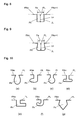
- Figs. 4 and 5 are perspective sectional views showing respectively different embodiments of the conventional molded composite articles. Since the embodiments are similar to each other, the same components are given the same symbols in Figs. 4 and 5 .
- a molded composite article 40 or 50 comprises a plate member 101 and a resin member 102.
- the plate member 101 and the resin member 102 are bonded to each other at a side end face 101SF of the plate member 101 and a side end face 102SF of the resin member 102 facing each other, to form a bonding interface 103JF.
- the bonding interface 103JF is shown as a bonding line 103JL on a surface of the molded composite article 40 or 50.
- the bonding line 103JL is a straight line.
- the direction of the straight line is usually in parallel to the direction of one side 104SE1 of the molded composite article 40 or 50. Owing to this constitution, in case of indicating a length on the bonding line 103JL, a wording of a parallel direction length may be used.
- the plate member 101 comprises surface layer base materials 105a and 105b positioned on the upper surface side and the lower surface side, and a core layer base material 106 positioned between these surface layer base materials 105a and 105b.
- the respective surface layer base materials 105a and 105b are formed of a fiber-reinforced resin.
- the fiber-reinforced resin comprises numerous continuous reinforcing fibers arranged in one direction and a matrix resin.
- the core layer base material 106 is formed of a soft material softer than the fiber-reinforced resin forming the respective surface layer base materials 105a and 105b. As the soft material, foam is used.
- the soft material of the core layer base material 106 is used to ensure that when a resin for forming the resin member 102 is injection-molded toward the plate member 101, the resin for forming the resin member 102 can compress the core layer base material 106 and penetrate into a region between both the surface layer base materials 105a and 105b.
- the side end face 102SF of the resin member 102 does not penetrate into the region between both the surface layer base materials 105a and 105b.
- a bonding projection 107 for supporting the plate member 101 from below is provided for the side end face 102SF of the resin member 102 at the region of the bonding interface 103JF.
- the thickness 102T of the resin member 102 is larger than the thickness 101T of the plate member 101.
- the molded composite article 40 is disadvantageous in view of weight reduction.
- the side end face 102SF of the resin member 102 penetrates into a region between both the surface layer base materials 105a and 105b.
- the penetration of the resin member 102 causes a tip portion 108 of the resin member 102 to be positioned in a space formed by the core layer base material 106 receding in the penetration direction. That is, the tip portion 108 of the resin member 102 is positioned between both the surface layer base materials 105a and 105b.
- a certain bonding strength can be secured between the plate member 101 and the resin member 102 at the bonding interface 103JF.
- the bonding line 103JL is a straight line, the penetration of the resin member 101 into the plate member 102 occurs only in the core layer base material 106, and it cannot be expected that the bonding strength between the plate member 101 and the resin member 102 is further enhanced.
- One of the objects of the molded composite article of the invention is to solve the problem of the conventional molded composite article 50 shown in Fig. 5 .
- An embodiment of the molded composite article of the invention is explained below in reference to Figs. 1 and 2 .
- Fig. 1 is a perspective sectional view showing an embodiment of the molded composite article of the invention.
- Fig. 2 is a perspective sectional view showing the plate member used in the molded composite article of Fig. 1 .
- a molded composite article 10 of the invention comprises a plate member 11 and a resin member 12.
- the plate member 11 and the resin member 12 are bonded to each other between an undulating side end face 11SF of the plate member 11 and an undulating side end face 12SF of the resin member 12 facing each other, to form a bonding interface 13JF as an undulating bonding interface.
- the bonding interface 13JF appears as a bonding line 13JL on a surface of the molded composite article 10. Since the bonding interface 13JF has an undulation form, the bonding line 13JL is an undulating curve.
- the plate member 11 comprises a surface layer base material 15a positioned on the upper surface side, a surface layer base material 15b positioned on the lower surface side and a core layer base material 16 positioned between these surface layer base materials 15a and 15b.
- the respective surface layer base materials 15a and 15b are formed of a fiber-reinforced resin.
- the core layer base material 16 is formed of a soft material softer than the fiber-reinforced resin forming the respective surface layer base materials 15a and 15b.
- the soft material of the core layer base material 16 is used to ensure that when a resin for forming the resin member 12 is injection-molded toward the plate member 11, the resin for forming the resin member 12 can compress the core layer base material 16 and penetrate into a region between both the surface layer base materials 15a and 15b. That is, a tip portion 18 of the resin member 12 is positioned between both the surface layer base materials 15a and 15b of the plate member 11.
- the molded composite article 10 has bonding interfaces 13JF2, 13JF3 and 13JF4 in addition to the bonding interface 13JF between the plate member 11 and the resin member 12. However, the bonding interface 13JF4 does not appear in Fig. 1 , since Fig. 1 is a sectional view.
- the respective bonding interfaces appear as bonding lines 13JL2, 13JL3 and 13JL4 in addition to the bonding line 13JL on the surface of the molded composite article 10. However, the bonding line 13JL4 does not appear in Fig. 1 , since Fig. 1 is a sectional view.
- the molded composite article 10 has a left side edge 10E, right side edge 10E2, upper side edge 10E3 and lower side edge 10E4 in Fig. 1 . However, the lower side edge 10E4 does not appear in Fig. 1 , since Fig. 1 is a sectional view.
- the direction of the left side edge 10E and the direction of the right side edge 10E2 are parallel to each other, and further, the direction of the upper side edge 10E3 and the direction of the lower side edge 10E4 are parallel to each other.
- the direction of the bonding line 13JL2 and the direction of the right side edge 10E2 are parallel to each other, and the direction of the bonding line 13JL3 and the direction of the upper side edge 10E3 are parallel to each other.
- the direction of the bonding line 13JL4 and the direction of the lower side edge 10E4 are parallel to each other.
- the bonding line 13JL having an undulating form progresses with undulation and the progress direction is parallel to the direction of the left side edge 10E. Owing to this constitution, in case of indicating a length on the bonding line, a wording of a parallel direction length may be used.
- a length JL of the actual bonding line formed along the undulation of the undulation form of the undulating bonding interface 13JF i.e., a length of the bonding line 13JL is 1.05 mm or more per 1 mm length of a projection-connecting line 13PL consisting of straight line segments connecting crests of the respective projections adjacent to each other in the undulation form of the respective surface layer base materials 15a and 15b. This value indicates the degree of undulation.
- the projection-connecting line 13PL is usually a straight line. Further, in the case where the projection-connecting line 13PL is a straight line, the direction of the projection-connecting line 13PL is usually the same as the direction of the left side edge 10E. That is, the projection-connecting line 13PL is a straight line parallel to the left side edge 10E. Since the bonding line 103JL of the molded composite article 40 shown in Fig. 4 or of the molded composite article 50 shown in Fig. 5 is not a curve of undulation, but a straight line, the length of the actual bonding line and the length of the bonding line 103JL are equal to each other.
- the bonding interface 13JF has such an undulation form, the bonding strength at the bonding interface is remarkably higher than that of the molded composite article 40 or 50 shown in Fig. 4 or 5 in which the bonding interface is a flat face.
- other bonding interfaces 13JF2, 13JF3 and 13JF4 can also be undulating bonding interfaces like the bonding interface 13JF as required.
- the size of the core layer base material 16 formed of a soft material can also be adjusted to ensure that the side end face of the core layer base material 16 may be positioned somewhat inside compared with the positions of the side end faces of the respective surface layer base materials 15a and 15b.
- the size of the tip portion 18 of the resin member 12 can be adjusted in response to the softness of the core layer base material 16, the injection pressure and the resin used to form the resin member 12.
- Fig. 3 is an exploded perspective view showing a crude laminate used to prepare the plate member 11 of the molded composite article 10 of Fig. 1 .
- a crude laminate 11A comprises a core layer base material 16A formed of foam as a soft material, a continuous reinforcing fiber sheet 11Aa with numerous fibers arranged in parallel in one direction disposed on the upper surface of the core layer base material 16A, a continuous reinforcing fiber sheet 11Ab with numerous fibers arranged in parallel in one direction disposed on the lower surface of the core layer base material 16A, a continuous reinforcing fiber sheet 11Ba with numerous fibers arranged in parallel in one direction disposed on the upper surface of the continuous reinforcing fiber sheet 11Aa, and furthermore a continuous reinforcing fiber sheet 11Bb with numerous fibers arranged in parallel in one direction disposed on the lower surface of the continuous reinforcing fiber sheet 11Ab.
- the direction in which continuous reinforcing fibers 31Aa are arranged in the continuous reinforcing fiber sheet 11Aa is perpendicular to the direction in which continuous reinforcing fibers 31Ba are arranged in the continuous reinforcing fiber sheet 11Ba.
- These continuous reinforcing fiber sheets form a surface layer base material 15aA on the upper surface side.
- the direction in which continuous reinforcing fibers 31Ab are arranged in the continuous reinforcing fiber sheet 11Ab is perpendicular to the direction in which continuous reinforcing fibers 31Bb are arranged in the continuous reinforcing fiber sheet 31Bb.
- These continuous reinforcing fiber sheets form a surface layer base material 15bA on the lower surface side.
- the method for bonding both the surface layer base materials 15aA and 15bA to the core layer base material 16A is not especially limited.
- a method of holding an adhesive nonwoven fabric or film between each of both the surface layer base materials 15aA and 15bA and the core layer base material 16A and press-molding can be suitably used.
- a method of applying an adhesive between each of both the surface layer base materials 15aA and 15bA and the core layer base material 16A can also be used.
- the method for producing the plate member 11 using the crude laminate 11A of the plate member is not especially limited.
- a press molding method, hand lay-up molding method, spray-up molding method, vacuum bag molding method, pressure molding method, autoclave molding method, transfer molding method, etc. respectively using a thermosetting resin can be used.
- a press molding method or stamping method respectively using a thermoplastic resin can also be used.
- a vacuum bag molding method, press molding method and transfer molding method can be suitably used.
- the method for bonding the resin member 12 to the plate member 11 is not especially limited. However, a method comprising the steps of setting the plate member 11 in a mold of an injection molding machine, clamping the mold and injection-molding a resin for forming the resin member 12 can be suitably used. Otherwise, for example, a method of preparing the plate member 11 and the resin member 12 respectively separately and bonding them to each other using an adhesive can also be used.
- the length of the bonding line 13JL is 1.05 mm or more per 1 mm length of the projection-connecting line 13PL consisting of straight line segments connecting the crests of the respective projections adjacent to each other in the undulation form of the respective surface layer base materials 15a and 15b.
- the load acting on the bonding interface 13JF if any, can be dispersed to remarkably enhance the bonding strength compared with the case where the length of the bonding line 13JL is less than 1.05 mm.
- the length of the bonding line 13JL per 1 mm length of the projection-connecting line 13PL is 1.10 mm or more, and more preferred is 1.15 mm or more. Meanwhile, if the length of the bonding line 13JL is longer, the bonding strength tends to be higher. However, even if the length is elongated to more than required, there is a limit to the enhancement of bonding strength and the processing of the plate member or the processing of the respective surface layer base materials becomes difficult. Considering these matters, it is preferred that the length of the bonding line 13JL per 1 mm length of the projection-connecting line 13PL is 5 mm or less.. More preferred is 4 mm or less.
- the method for preparing the undulation form at the side end face 11SF of the plate member or the respective surface layer base materials is not especially limited. However, a numerically controlled end mill or milling cutter or the like can be used for processing even a complicated undulation form.
- the number of projections PAn in the undulation form of the respective surface layer base materials 15a and 15b at the bonding interface 13JF is 1 to 100 per 100 mm length of the projection-connecting line 13PL.
- the recess depth Ln is 0.5 to 100 mm.
- the number of projections PAn is 3 to 80 per 100 mm length of the projection-connecting line 13PL. In this case, it is more preferred that the recess depth Ln is 1 to 80 mm.
- the number of projections PAn is 5 to 60 per 100 mm length of the projection-connecting line 13PL. In this case, it is further more preferred that the recess depth Ln is 2 to 60 mm.
- the bonding strength may be insufficient since the load cannot be dispersed. Further, if the number of projections PAn is more than 100 per 100 mm length of the projection-connecting line 13PL and the recess depth Ln is more than 100 mm, it may be difficult to process the plate member 11 or the surface layer base materials 15a and 15b, or processing time and cost may increase.
- Figs. 6 through 9 are plan views showing some undulating bonding interfaces with respectively different undulations to be formed at the side end faces of the surface layer base materials.
- symbol JL denotes a bonding line at which the resin member bonds.
- Symbol PAn and Symbol PAn+1 denote projections adjacent to each other.
- Symbol Pn denotes a recess formed between the projections PAn and PAn+1 adjacent to each other.
- Symbol PL denotes the projection-connecting line consisting of straight line segments connecting the crests of the projections PAn and PAn+1 respectively adjacent to each other.
- Symbol Ln denotes the distance from the projection-connecting line PL to the recess bottom of each recess Pn, i.e., recess depth.
- Symbol Fn is the distance between both the ends of the recess opening line formed as a line segment of the projection-connecting line PL within the form of each recess Pn, i.e., the recess opening width.
- the recess depth Ln is 0.1 to 10 times the recess opening width Fn.
- a more preferred range is 0.5 to 8 times, and a further more preferred range is 1 to 5 times.
- each recess Pn partially contains a roundish line segment. If each recess Pn contains a roundish line segment, the length of the actual bonding line JL can be elongated, and the stress concentration likely to occur in the case where there is a sharp portion can be prevented.
- Each recess Pn may have a portion wider than the recess opening width Fn.
- the recess Pn shown in Fig. 9 the right bonding line segment JL and the left bonding line segment JL of the recess Pn become distant from each other as they extend toward the bottom of the recess Pn. That is, the recess Pn of Fig. 9 has a portion wider than the recess opening width Fn. If the recess Pn has a portion wider than the recess opening width Fn, in the case where a tensile force acts in the direction perpendicular to the bonding interface JF, an anchor effect can be enlarged.
- Fig. 10 (a) through (g) Plan views of other seven examples of the recess Pn having a portion wider than the recess opening width Fn are shown in Fig. 10 (a) through (g) .
- the form of the recess Pn of Fig. 10 (a) is a liquid drop form.
- the form of the recess Pn of Fig. 10 (b) is a musical note form.
- the form of the recess Pn of Fig. 10 (c) is a pendulum form.
- the form of the recess Pn of Fig. 10 (d) is a dovetail groove form or T letter form.
- the form of the recess Pn of Fig. 10 (e) is key-like form or L letter form.
- the form of the recess Pn of Fig. 10 (f) is a tail form or J letter form.
- the form of the recess Pn of Fig. 10 (g) is a polygonal form typified by
- the surface layer base materials 15a and 15b of the plate member 11 are formed of a fiber-reinforced resin, and a resin used therein, i.e., a matrix resin is a thermoplastic resin or thermosetting resin.
- thermoplastic resin examples include polyolefins such as polyethylene (PE), polypropylene (PP) and polybutylene, styrene-based resins such as polystyrene (PS), acrylonitrile-butadiene-styrene copolymer (ABS) and acrylonitrile-styrene copolymer (AS), polyesters such as polyethylene terephthalate (PET), polybutylene terephthalate (PBT), polytrimethylene terephthalate (PTT), polyethylene naphthalate (PEN) and liquid crystal polyesters, polyoxymethylene (POM), polyamide (PA), polycarbonate (PC), polymethyl methacrylate (PMMA), polyvinyl chloride (PVC), polyphenylene sulfide (PPS), polyphenylene ether (PPE), modified PPE, thermoplastic polyimide (PI), polyamideimide (PAI), polyetherimide (PEI), polysulfone (PSU), modified PPE
- thermosetting resin examples include unsaturated polyester, vinyl ester, epoxy, phenol (resol type), urea-melamine, polyimide, etc., copolymers and modification products thereof, and polymer alloys consisting of at least two of the foregoing.
- thermosetting resin excellent in stiffness and strength is preferred, and a thermosetting resin mainly composed of an epoxy resin is more preferred in view of the mechanical properties of the molded article.
- a thermoplastic resin and/or any other elastomer or rubber component can also be added to the thermosetting resin.
- the reinforcing fibers used include inorganic fibers, for example, metal fibers such as aluminum fibers, brass fibers and stainless steel fibers, carbon fibers such as polyacrylonitrile-based, rayon-based, lignin-based and pitch-based carbon fibers, graphite fibers, glass fibers, silicon carbide fibers and silicon nitride fibers, and organic fibers such as aramid fibers, polypara-phenylene-benzobisoxazole (PBO) fibers, polyphenylene sulfide fibers, polyester fibers, acrylic fibers, nylon fibers and polyethylene fibers. Any one type of these reinforcing fibers can be used or two or more types can also be used together.
- metal fibers such as aluminum fibers, brass fibers and stainless steel fibers
- carbon fibers such as polyacrylonitrile-based, rayon-based, lignin-based and pitch-based carbon fibers, graphite fibers, glass fibers, silicon carbide fibers and silicon nitride fiber
- carbon fibers are preferred as the reinforcing fibers, and in view of excellent specific strength and specific modulus, it is preferred to contain at least polyacrylonitrile-based carbon fibers.
- the reinforcing fibers of the respective surface layer base materials 15a and 15b can also be a reinforcing fiber sheet comprising multiple layers containing reinforcing fibers. It is preferred that the reinforcing fibers are continuous reinforcing fibers, since higher strength and higher stiffness can be obtained.
- the length of the continuous reinforcing fibers in a reinforcing fiber sheet containing the continuous reinforcing fibers is only required to be 10 mm or more. However, it is not necessarily required that the reinforcing fibers are continuous throughout the entire reinforcing fiber sheet and can also remain cut intermediately.
- the mode of the continuous reinforcing fibers can be, for example, cloth, unidirectional fiber sheet or braid.
- cloth or unidirectional fiber sheet can be suitably used. Any one of these modes can be used alone or two or more of them can also be used together. Above all, a sheet with multifilaments arranged in parallel in one direction is preferred, since strength and stiffness can be obtained more efficiently.
- the rate of the reinforcing fibers is 20 to 90 vol% in view of moldability and mechanical properties. A more preferred range is 30 to 80 vol%.
- the vol% is measured according to the method described in JIS K 7075-1991 (Fiber Content and Void Content Testing Methods for Carbon Fiber Reinforced Plastics).
- the resin used in the resin member 12 is not especially limited, but a thermoplastic resin can be preferably used in view of the preparation of the bonding form by using injection molding, etc.
- thermoplastic resin used for forming the resin member any of the abovementioned thermoplastic resins used for forming the plate member can be used.
- PPS polyphenylene sulfide
- PC polycarbonate
- PPE polyphenylene ether
- styrene-based resin styrene-based resin
- PA polyamide
- a resin containing reinforcing fibers as the resin of the resin member 12.
- the abovementioned reinforcing fibers can be enumerated.
- non-conductive glass fibers as the reinforcing fibers.
- the soft material forming the core layer base material 16 of the plate member 11 for example, a porous material such as foam or honeycomb material, fiber sheet or resin sheet can be used. If foam and/or a honeycomb material is used, a plate member 11 having a lighter weight can be obtained.
- the material of the soft material is not especially limited.
- the soft material is a thermoplastic resin
- any of the abovementioned thermoplastic resins used for forming the plate member can be used.
- a polyolefin-based resin such as polypropylene (PP) or polyethylene (PE)
- PP polypropylene
- PE polyethylene
- a polyamide-based resin, polyester-based resin, polyvinyl alcohol-based resin, modified polyolefin, or a copolymer or polymer alloy thereof can be preferably used.
- the soft material may also contain reinforcing fibers such as glass fibers or carbon fibers.
- the method for bonding the respective surface layer base materials 15a and 15b and the core layer base material 16 to each other is not especially limited.
- An adhesive nonwoven fabric, film or the like may be interposed between each of the surface layer base materials and the core layer base material, for bonding, or either or both of the base materials may also be coated with an adhesive for bonding.
- the molded composite article of the invention can be applied, for example, to the components of the housings of electric and electronic devices such as personal computers, displays, OA devices, cell phones, portable information terminals, facsimiles, compact disc players, portable MD players, portable radio cassettes, PDA (portable information terminals such as electronic organizers), digital video cameras, digital still cameras, optical devices, audio devices, air conditioners, illumination devices, amusement articles, toys and other household electric appliances. Further, it can also be applied to components of trays, chassis and cases, components of various mechanical parts, and components of electric equipment members and internal parts of automobiles and aircraft.
- the molded composite article of the invention can be suitably used as the components of the housings of electric and electronic devices since the molded composite article has a light weight, high strength, high stiffness and thin wall. Further, it can be suitably used as the components of the housings of notebook personal computers and portable information terminals requiring thin-walled wide displays.
- the molded composite article of the invention has flame retardancy. It is preferred that the flame retardancy of the plate member 11 and the resin member 12 in a vertical flame test based on UL-94 standard is V-1 or V-0 when a specimen having a thickness of 0.1 1 to 3.0 mm is used. More preferred is V or V-0 when a specimen having a thickness of 0.1 to 1.0 mm is used.
- the plate member 11 and/or the resin member 12 contains a flame retarder.
- the flame retarder include halogen compounds, antimony compounds, phosphorus compounds, nitrogen compounds, silicone compounds, fluorine compounds, phenol compounds and metal hydroxides. Among them, in view of inhibiting environmental load, a phosphorus-based flame retarder is preferred.
- the phosphorus-based flame retarder include phosphorus-containing compounds such as phosphoric esters, condensed phosphoric acid esters and phosphaphenanthrene-based compounds, and red phosphorus. Among them, since red phosphorus is large in the phosphorus atom content functioning to impart flame retardancy, the amount of red phosphorus added as a flame retarder for obtaining a sufficient flame retardant effect can be small.
- the resin used for the plate member 11 and the resin member 12 may also contain a filler and other additives to such an extent that the object of the invention is not impaired.
- the filler and other additives include an inorganic filler, electrically conducting agent, crystal nucleating agent, ultraviolet light absorber, antioxidant, vibration damper, antimicrobial agent, insecticide, deodorant, coloration preventive, thermal stabilizer, releasing agent, antistatic agent, hydrophilizing agent, plasticizer, lubricant, colorant, pigment, dye, foaming agent, foam stabilizer and coupling agent.
- the length of the recurring undulation units at the undulating bonding interface of the molded composite article 10 obtained by injection molding was obtained by measuring using a rule and by calculation. In the case where there was a roundish line segment in the profile line of the undulation form, the radius or diameter of the roundness was measured, and the formula for obtaining the circumference from the value was used to calculate the length of the actual bonding line.
- the total of the lengths of the recurring undulation units of the bonding line was divided by the length of the straight projection-connecting line, i.e., by the parallel direction length, to obtain the length of the actual bonding line per 1 mm length of the projection-connecting line, i.e., per 1 mm parallel direction length.
- the length of the recurring undulation units at the undulating bonding interface of the molded composite article 10 obtained by injection molding was obtained by measuring using a rule and by calculation. In the case where there was a roundish line segment in of the profile line of the undulation form, the radius or diameter of the roundness was measured, and the formula for obtaining the circumference from the value was used to calculate the length of the actual bonding line. Since one projection existed every recurring undulation unit, the length of the projection-connecting line per recurring unit was measured using a rule, and 100 mm was divided by the length of the projection-connecting line per recurring unit, to obtain the number of projections per 100 mm length of the projection-connecting line.
- the depth of a recess of the molded composite article 10 obtained by injection molding was measured using a rule.
- the opening width of a recess of the molded composite article 10 obtained by injection molding was measured using a rule.
- two laminates each comprising two unidirectional carbon fiber prepreg sheets (UD PP) P3052S-12 [carbon fiber T700S (strength 4900 MPa, elastic modulus 230 GPa, carbon fiber weight content 67 wt%, base resin : epoxy resin) produced by Toray Industries, Inc.] laminated on each other with their fiber directions kept perpendicular to each other, were prepared, and one of the laminates was used as the surface layer base material 15a of the upper surface side, while the other laminate was used as the surface layer base material 15b of the lower surface side.
- foam product number RC2010 of EFSEL, registered trademark, produced by Furukawa Electric Co., Ltd.] (twice-expanded polypropylene) was prepared.
- an adhesive polyolefin nonwoven fabric (melting point 150°C, unit weight per area 15 g/m 2 produced by Japan Vilene Company) was placed, and further on the upper and lower surfaces of the laminate, the prepared surface layer base materials 15a and 15b were placed.
- the laminate was then press-molded (mold temperature 160°C, pressure 6 MPa, preheating time 5 minutes, curing time 30 minutes), to obtain a plate-like body.
- the obtained plate-like body was processed to have a size of 300 mm ⁇ 230 mm and NC-machined to form the undulating bonding interface shown in Example 1 of Table 1 and Fig. 6 at the side end of the obtained plate-like body, to prepare a plate member 11.
- the plate member 11 was set in an injection molding mold, and the mold was clamped.
- Fiber-reinforced copolymerized polyamide resin CM3511-G60 glass fiber content 60 wt%, produced by Toray Industries, Inc.
- CM3511-G60 glass fiber content 60 wt%, produced by Toray Industries, Inc.
- the resin to be formed into a resin member 12 was injection-molded to produce a molded composite article 10 as shown in Fig. 1 , in which the side end on the side opposite to the vertical wall 19 of the resin member 12 having the vertical wall 19 penetrated into the undulation form of the plate member 11, to ensure that the resin member 12 might be bonded to the plate member 11 via the undulating boding interface 13JF.
- the thickness of the resin member 12 in the region from the vertical wall 19 to the undulating bonding interface 13JF was 1.5 mm
- the width of the resin member 12 along the left edge 10E was 30 mm.
- a molded composite article was prepared according to the same method as described in Example 1, except that the undulating bonding interface shown in Example 2 of Table 1 and Fig. 7 was formed by NC machining in the plate-like body of Example 1.
- a molded composite article was prepared according to the same method as described in Example 1, except that the undulating bonding interface shown in Example 3 of Table 1 and Fig. 7 was formed by NC machining in the plate-like body of Example 1.
- a molded composite article was prepared according to the same method as described in Example 1, except that the undulating bonding interface shown in Example 4 of Table 2 and Fig. 8 was formed by NC machining in the plate-like body of Example 1.
- a molded composite article was prepared according to the same method as described in Example 1, except that the undulating bonding interface shown in Example 5 of Table 2 and Fig. 9 was formed by NC machining in the plate-like body of Example 1.
- a molded composite article 50 shown in Fig. 5 was prepared according to the same method as described in Example 1, except that the straight bonding interface shown in Comparative Example 1 of Table 3 was formed by NC machining in the plate-like body of Example 1.
- two laminates each comprising two unidirectional carbon fiber prepreg sheets (UD PP) P3052S-12 [carbon fiber T700S (strength 4900 MPa, elastic modulus 230 GPa, carbon fiber weight content 67 wt%, base resin : epoxy resin) produced by Toray Industries, Inc.] laminated on each other with their fiber directions kept perpendicular to each other, were prepared, and one of the laminates was used as the surface layer base material 105a of the upper surface side, while the other laminate was used as the surface layer base material 105b of the lower surface side.
- foam product number RC2010 of EFSEL, registered trademark, produced by Furukawa Electric Co., Ltd.
- an adhesive polyolefin nonwoven fabric (melting point 150°C, unit weight per area 15 g/m 2 produced by Japan Vilene Company) was placed, and further on the upper and lower surfaces of the laminate, the prepared surface layer base materials 105a and 105b were placed, to prepare a crude laminate destined to be a plate member 101.
- a molded resin article destined to be a resin member 102 was prepared.
- the molded resin article had an overlapping portion (bonding projection 107) (3 mm wide, 1 mm thick) to be mounted with the end of the plate member 101.
- a molded composite article 40 shown in Fig. 4 was prepared according to the same method as in Example 1, except that the molded composite article was processed to have a size of 300 mm ⁇ 230 mm and NC-machined to form a straight bonding interface shown in Comparative Example 2 of Table 3.
- the tensile cracking loads of the molded composite articles of Examples 1 through 5 were measured, and it was confirmed that sufficient bonding strengths were obtained.
- the molded composite articles did not have a joint at which the plate member and the resin member overlapped on each other, and therefore could have a thinner wall accordingly.
- a sufficient tensile cracking load could not be obtained, and the joint warping was also large.
- the tensile cracking load was sufficient, but owing to the existence of the overlapping portion, a thin wall could not be achieved.
- Example 1 Example 2
- Example 3 Surface layer base material Item 1 Carbon fibers Carbon fibers Carbon fibers
- Item 2 Epoxy-based Epoxy-based Epoxy-based Core layer base material
- Item 3 Polypropylene Polypropylene Polypropylene Resin member
- Item 4 Glass fibers Glass fibers Glass fibers Item 5 Polyamide-based Polyamide-based Polyamide-based Item 6 Fig. 6 Fig. 7 Fig. 7 Item 7 Yes Yes Yes Item 8 1.97 1.57 1.57 Item 9 7.7 50.0 5.0
- Item 10 8.0 1.0 10.0
- Item 11 8.0 2.0
- Item 12 1.0 0.5 0.5 Item 13
- No No No Mechanical strength Item 14 1,300 700 1,250 Joint warping Item 15 0.1 0.1 0.2
- Example 4 Example 5 Surface layer base material Item 1 Carbon fibers Carbon fibers Item 2 Epoxy-based Epoxy-based Core layer base material Item 3 Polypropylene Polypropylene Resin member Item 4 Glass fibers Glass fibers Item 5 Polyamide-based Polyamide-based Item 6 Fig. 8 Fig. 9 Item 7 No Yes Item 8 1.10 2.09 Item 9 5.0 7.7 Item 10 1.0 8.0 Item 11 1.0 8.0 Item 12 1.0 1.0 Item 13 No No Mechanical strength Item 14 750 1,800 Joint warping Item 15 0.1 0.1 0.1
- the molded composite article of the invention can be suitably used as components of the housings of electric and electronic devices such as notebook personal computers and cell phones, and further suitably used also as components of automobile parts since the molded composite article has a light weight, high strength, high stiffness and thin wall.
Landscapes
- Engineering & Computer Science (AREA)
- Mechanical Engineering (AREA)
- Manufacturing & Machinery (AREA)
- Injection Moulding Of Plastics Or The Like (AREA)
- Laminated Bodies (AREA)
- Moulds For Moulding Plastics Or The Like (AREA)
- Lining Or Joining Of Plastics Or The Like (AREA)
Applications Claiming Priority (2)
| Application Number | Priority Date | Filing Date | Title |
|---|---|---|---|
| JP2007235036 | 2007-09-11 | ||
| PCT/JP2008/065939 WO2009034906A1 (ja) | 2007-09-11 | 2008-09-04 | 複合成形品およびその製造方法 |
Publications (3)
| Publication Number | Publication Date |
|---|---|
| EP2199064A1 true EP2199064A1 (de) | 2010-06-23 |
| EP2199064A4 EP2199064A4 (de) | 2011-03-23 |
| EP2199064B1 EP2199064B1 (de) | 2012-11-28 |
Family
ID=40451915
Family Applications (1)
| Application Number | Title | Priority Date | Filing Date |
|---|---|---|---|
| EP08830434A Not-in-force EP2199064B1 (de) | 2007-09-11 | 2008-09-04 | Geformter verbundartikel und verfahren zu seiner herstellung |
Country Status (8)
| Country | Link |
|---|---|
| US (1) | US8173238B2 (de) |
| EP (1) | EP2199064B1 (de) |
| JP (1) | JP4858544B2 (de) |
| KR (1) | KR101196787B1 (de) |
| CN (1) | CN101835596B (de) |
| ES (1) | ES2397240T3 (de) |
| TW (1) | TWI378027B (de) |
| WO (1) | WO2009034906A1 (de) |
Cited By (5)
| Publication number | Priority date | Publication date | Assignee | Title |
|---|---|---|---|---|
| FR2998826A1 (fr) * | 2012-12-03 | 2014-06-06 | Peugeot Citroen Automobiles Sa | Insert pourvu d'un dissipateur de contraintes dentele pour liaison bi-matiere |
| WO2020049056A1 (en) * | 2018-09-06 | 2020-03-12 | Covestro Deutschland Ag | Molded composite article, method for the production thereof and use thereof |
| EP3650191A1 (de) * | 2018-11-06 | 2020-05-13 | Covestro Deutschland AG | Geformter verbundartikel, verfahren zur herstellung davon und verwendung davon |
| EP4431381A1 (de) | 2023-03-16 | 2024-09-18 | AIRBUS HELICOPTERS DEUTSCHLAND GmbH | Anordnung einer klebeverbindung auf einem strukturteil |
| EP4600148A1 (de) | 2024-02-07 | 2025-08-13 | AIRBUS HELICOPTERS DEUTSCHLAND GmbH | Strukturverbundene anordnung |
Families Citing this family (44)
| Publication number | Priority date | Publication date | Assignee | Title |
|---|---|---|---|---|
| JP5584398B2 (ja) * | 2008-05-14 | 2014-09-03 | 三菱電機株式会社 | 筐体用パネルおよびその製造方法と、この筐体用パネルを備えた電子機器 |
| JP5458529B2 (ja) * | 2008-08-22 | 2014-04-02 | 東レ株式会社 | 接合方法および一体化成形品 |
| JP5648270B2 (ja) * | 2009-04-24 | 2015-01-07 | 三菱レイヨン株式会社 | 繊維強化複合材料成形品とその製造方法 |
| WO2011086959A1 (ja) | 2010-01-13 | 2011-07-21 | 東レ株式会社 | 射出成形品およびその製造方法 |
| JP2011166124A (ja) * | 2010-01-14 | 2011-08-25 | Toray Ind Inc | 電気・電子機器筐体 |
| TWI383883B (zh) * | 2010-11-04 | 2013-02-01 | Advanced Int Multitech Co Ltd | Manufacturing Method of Composite Workpiece with Embedded Magnetic Element |
| US10059078B2 (en) * | 2012-03-23 | 2018-08-28 | Cutting Dynamics, Inc. | Injection molded composite blank and guide |
| US9393745B2 (en) * | 2012-05-15 | 2016-07-19 | Hexcel Corporation | Over-molding of load-bearing composite structures |
| US10265928B2 (en) | 2012-07-18 | 2019-04-23 | Mitsubishi Chemical Corporation | Fiber reinforced composite material structure, composite material molded body using the same, and manufacturing method therefor |
| US9801294B2 (en) * | 2012-11-29 | 2017-10-24 | Sunteng New Technology Co., Ltd. | Electronic device casing including coupling structure and method of manufacturing same |
| JP5972854B2 (ja) * | 2013-12-17 | 2016-08-17 | 三菱重工業株式会社 | 繊維強化複合部材の接合方法及び接合体、並びに風車翼の製造方法 |
| TWI562895B (en) * | 2014-06-11 | 2016-12-21 | Compal Electronics Inc | Composite plate structure and manufacturing method thereof |
| BE1021929B1 (nl) | 2014-07-04 | 2016-01-27 | Unilin Bvba | Vloerpaneel |
| CN105504788B (zh) * | 2014-09-30 | 2016-09-07 | 比亚迪股份有限公司 | 一种不同种类树脂的注塑成型品及其制备方法和由该方法制备的注塑成型品及其应用 |
| US10500814B2 (en) * | 2014-12-08 | 2019-12-10 | Dell Products L.P. | Thermoplastic composite materials for portable information handling system enclosures |
| CN105372823B (zh) * | 2015-12-08 | 2017-10-27 | 上海天马微电子有限公司 | 立体显示装置 |
| JP2017136740A (ja) * | 2016-02-03 | 2017-08-10 | レノボ・シンガポール・プライベート・リミテッド | 積層板、筐体用部材、電子機器及び筐体用部材の製造方法 |
| WO2017176250A1 (en) * | 2016-04-05 | 2017-10-12 | Hewlett-Packard Development Company, L.P. | Multilayer structures for electronic device housings |
| US10723100B2 (en) * | 2016-05-02 | 2020-07-28 | Nissan Motor Co., Ltd. | Fiber-reinforced resin molded article and method for manufacturing same |
| US10668674B2 (en) * | 2016-05-18 | 2020-06-02 | Dell Products L.P. | Apparatus and method for a high performance carbon fiber laminate enclosure part for an information handling system |
| KR101806707B1 (ko) * | 2016-06-09 | 2017-12-07 | 현대자동차주식회사 | 차량용 글로브 박스의 니 볼스터 장치 |
| BE1024734B1 (nl) | 2016-11-10 | 2018-06-19 | Ivc Bvba | Vloerpaneel en werkwijze voor het vervaardigen van een vloerpaneel |
| CN106696312A (zh) * | 2017-01-25 | 2017-05-24 | 合肥联宝信息技术有限公司 | 复合板材埋入成型工艺、复合板材及成型铣刀 |
| JP6823519B2 (ja) * | 2017-03-24 | 2021-02-03 | 日鉄ケミカル&マテリアル株式会社 | 繊維強化複合材料成形体及びその製造方法 |
| JP6859822B2 (ja) | 2017-04-14 | 2021-04-14 | トヨタ紡織株式会社 | 樹脂成形体及びその製造方法 |
| CN109270992A (zh) * | 2017-07-17 | 2019-01-25 | 仁宝电脑工业股份有限公司 | 板状构件、包含板状构件的壳体及其制作方法 |
| JP6491720B1 (ja) * | 2017-09-26 | 2019-03-27 | レノボ・シンガポール・プライベート・リミテッド | 筐体用部材の製造方法、積層板、筐体用部材及び電子機器 |
| WO2020014936A1 (zh) * | 2018-07-20 | 2020-01-23 | 五行科技股份有限公司 | 一种板状构件、复合成型构件及复合成型构件的制造方法 |
| CN109551833A (zh) * | 2018-11-23 | 2019-04-02 | 合肥联宝信息技术有限公司 | 一种复合材料的结构及加工方法 |
| CN109677028A (zh) * | 2018-12-29 | 2019-04-26 | 上海超惠通风环保设备有限公司 | 一种轻质高强先进复合材料结构 |
| JP7226127B2 (ja) * | 2019-06-20 | 2023-02-21 | トヨタ紡織株式会社 | 乗物用内装材の製造方法 |
| WO2021001210A1 (en) * | 2019-07-01 | 2021-01-07 | Basf Se | Overmoulding a profile for producing a shaped article, a shaped article obtained therefrom and use thereof |
| CN112824099A (zh) * | 2019-11-20 | 2021-05-21 | 虞霞 | 复合板、具有该复合板的壳体以及该复合板的制造方法 |
| CN112825607A (zh) * | 2019-11-20 | 2021-05-21 | 虞霞 | 复合板 |
| CN113022060A (zh) * | 2019-12-25 | 2021-06-25 | 五行科技股份有限公司 | 复合构件 |
| CN111267452B (zh) * | 2020-01-21 | 2021-02-09 | 江苏奇一科技有限公司 | 连续蜂窝芯材、蜂窝芯三明治复合板及其制备方法和设备 |
| CN113811104B (zh) * | 2020-06-17 | 2024-11-12 | 五行科技股份有限公司 | 复合板材及其制造方法 |
| CN113799316A (zh) * | 2020-06-17 | 2021-12-17 | 五行科技股份有限公司 | 复合板材的制造方法 |
| CN112389041A (zh) * | 2020-11-27 | 2021-02-23 | 中科威禾科技(肇庆)有限公司 | 一种树脂层压板和金属板的复合体及其制造方法 |
| JP7526084B2 (ja) | 2020-12-04 | 2024-07-31 | ニッタ株式会社 | ワイパー |
| JP7512919B2 (ja) * | 2021-02-02 | 2024-07-09 | トヨタ自動車株式会社 | ハイブリッド成形体、成形装置、及び成形方法 |
| JPWO2022265062A1 (de) * | 2021-06-18 | 2022-12-22 | ||
| DE102021124090A1 (de) | 2021-09-17 | 2023-03-23 | 4A Manufacturing Gmbh | Integrierte Rahmenstruktur |
| CN120239199A (zh) * | 2023-12-28 | 2025-07-01 | 华为技术有限公司 | 电子设备、复合板及其制备方法 |
Family Cites Families (14)
| Publication number | Priority date | Publication date | Assignee | Title |
|---|---|---|---|---|
| JPS4815017Y1 (de) | 1970-04-14 | 1973-04-25 | ||
| DE2111257B2 (de) * | 1971-03-09 | 1974-02-07 | Fleuchaus, Leo, Dipl.-Ing., 8000 Muenchen | Nut-Feder-Verbindung zwischen dem Deck und der Bootskörperschale eines Kunststoff-Bootskörpers |
| JPS62159619A (ja) | 1986-01-09 | 1987-07-15 | 松下電器産業株式会社 | 電気炊飯器 |
| JPS62159619U (de) * | 1986-03-31 | 1987-10-09 | ||
| JPH0694166B2 (ja) | 1991-04-03 | 1994-11-24 | ニッタ株式会社 | 熱可塑性樹脂帯の端部相互を融着する為の金型 |
| US5616396A (en) * | 1991-11-25 | 1997-04-01 | Kasai Kogyo Co., Ltd. | Automotive door trim with attachment joined during molding |
| JPH05329880A (ja) | 1992-06-03 | 1993-12-14 | Fujitsu Ltd | 複合筐体の製造方法 |
| DE19842725A1 (de) | 1998-09-18 | 2000-03-23 | Micafil Ag Zuerich | Formschlüssige Einbettung |
| JP2004001424A (ja) * | 2002-04-04 | 2004-01-08 | Canon Inc | 射出成形方法及び射出成形用金型及び樹脂成形品及びインサート樹脂部品 |
| US7731817B2 (en) * | 2003-02-24 | 2010-06-08 | Bell Helicopter Textron Inc. | Interlocking tooth bond for assembly of fiber composite laminates |
| JP2006044259A (ja) | 2004-07-07 | 2006-02-16 | Toray Ind Inc | 一体化成形品およびその製造方法 |
| TWI353303B (en) * | 2004-09-07 | 2011-12-01 | Toray Industries | Sandwich structure and integrated molding using th |
| JP4670532B2 (ja) * | 2005-08-03 | 2011-04-13 | 東レ株式会社 | 複合成形品 |
| JP5051648B2 (ja) * | 2008-01-11 | 2012-10-17 | レノボ・シンガポール・プライベート・リミテッド | 電子機器の筐体構造および電子機器 |
-
2008
- 2008-09-04 US US12/677,387 patent/US8173238B2/en active Active
- 2008-09-04 WO PCT/JP2008/065939 patent/WO2009034906A1/ja not_active Ceased
- 2008-09-04 ES ES08830434T patent/ES2397240T3/es active Active
- 2008-09-04 CN CN2008801063763A patent/CN101835596B/zh active Active
- 2008-09-04 EP EP08830434A patent/EP2199064B1/de not_active Not-in-force
- 2008-09-04 KR KR1020107003598A patent/KR101196787B1/ko not_active Expired - Fee Related
- 2008-09-04 JP JP2008544681A patent/JP4858544B2/ja active Active
- 2008-09-10 TW TW097134657A patent/TWI378027B/zh active
Cited By (5)
| Publication number | Priority date | Publication date | Assignee | Title |
|---|---|---|---|---|
| FR2998826A1 (fr) * | 2012-12-03 | 2014-06-06 | Peugeot Citroen Automobiles Sa | Insert pourvu d'un dissipateur de contraintes dentele pour liaison bi-matiere |
| WO2020049056A1 (en) * | 2018-09-06 | 2020-03-12 | Covestro Deutschland Ag | Molded composite article, method for the production thereof and use thereof |
| EP3650191A1 (de) * | 2018-11-06 | 2020-05-13 | Covestro Deutschland AG | Geformter verbundartikel, verfahren zur herstellung davon und verwendung davon |
| EP4431381A1 (de) | 2023-03-16 | 2024-09-18 | AIRBUS HELICOPTERS DEUTSCHLAND GmbH | Anordnung einer klebeverbindung auf einem strukturteil |
| EP4600148A1 (de) | 2024-02-07 | 2025-08-13 | AIRBUS HELICOPTERS DEUTSCHLAND GmbH | Strukturverbundene anordnung |
Also Published As
| Publication number | Publication date |
|---|---|
| JP4858544B2 (ja) | 2012-01-18 |
| ES2397240T3 (es) | 2013-03-05 |
| TWI378027B (en) | 2012-12-01 |
| KR20100053562A (ko) | 2010-05-20 |
| EP2199064B1 (de) | 2012-11-28 |
| JPWO2009034906A1 (ja) | 2010-12-24 |
| US20110008566A1 (en) | 2011-01-13 |
| CN101835596B (zh) | 2012-08-29 |
| WO2009034906A1 (ja) | 2009-03-19 |
| EP2199064A4 (de) | 2011-03-23 |
| TW200924956A (en) | 2009-06-16 |
| US8173238B2 (en) | 2012-05-08 |
| CN101835596A (zh) | 2010-09-15 |
| KR101196787B1 (ko) | 2012-11-05 |
Similar Documents
| Publication | Publication Date | Title |
|---|---|---|
| US8173238B2 (en) | Composite shaped article and process for manufacturing the same | |
| JP5344032B2 (ja) | 射出成形品およびその製造方法 | |
| US9073291B2 (en) | Polymer over molding of strengthened glass | |
| JP5776137B2 (ja) | 一体化成形品の製造方法 | |
| JP6617557B2 (ja) | 積層体および一体化成形品 | |
| JP4774839B2 (ja) | 繊維強化複合材料の製造方法 | |
| JP2010253937A (ja) | 一体化成形品 | |
| JP4670532B2 (ja) | 複合成形品 | |
| CN101085865A (zh) | 用于热结合的基材及用其制造层压品的方法 | |
| JPWO2016002457A1 (ja) | 積層体および一体化成形品 | |
| JP2011166124A (ja) | 電気・電子機器筐体 | |
| JP2006044262A (ja) | 中空成形体およびその製造方法 | |
| JP2009220478A (ja) | 繊維強化サンドイッチ構造複合体、複合成形体 | |
| JP2010131804A (ja) | 複合成形品およびその製造方法 | |
| JP2006130862A (ja) | 複合成形品および複合成形品の製造方法 | |
| EP3771959A1 (de) | Gehäuse für tragbare elektronische vorrichtungen mit hybridlaminatseitenwänden und verfahren zur herstellung davon | |
| JP2009173027A (ja) | 複合成形品の製造方法 | |
| JP2006044260A (ja) | 一体化構造部材およびその製造方法 | |
| JP2010046938A (ja) | 複合成形品およびその製造方法 | |
| JP2008114525A (ja) | 複合成形品 | |
| CN110877477A (zh) | 复合成型品及其制备方法和用途 | |
| JP2005271583A (ja) | 射出成形金型および複合射出成形品 | |
| EP3846993B1 (de) | Verfahren zur herstellung eines geformten verbundartikel | |
| EP3650191A1 (de) | Geformter verbundartikel, verfahren zur herstellung davon und verwendung davon | |
| JP6049537B2 (ja) | 金属/樹脂複合構造体 |
Legal Events
| Date | Code | Title | Description |
|---|---|---|---|
| PUAI | Public reference made under article 153(3) epc to a published international application that has entered the european phase |
Free format text: ORIGINAL CODE: 0009012 |
|
| 17P | Request for examination filed |
Effective date: 20100305 |
|
| AK | Designated contracting states |
Kind code of ref document: A1 Designated state(s): AT BE BG CH CY CZ DE DK EE ES FI FR GB GR HR HU IE IS IT LI LT LU LV MC MT NL NO PL PT RO SE SI SK TR |
|
| AX | Request for extension of the european patent |
Extension state: AL BA MK RS |
|
| DAX | Request for extension of the european patent (deleted) | ||
| A4 | Supplementary search report drawn up and despatched |
Effective date: 20110222 |
|
| GRAP | Despatch of communication of intention to grant a patent |
Free format text: ORIGINAL CODE: EPIDOSNIGR1 |
|
| GRAS | Grant fee paid |
Free format text: ORIGINAL CODE: EPIDOSNIGR3 |
|
| GRAA | (expected) grant |
Free format text: ORIGINAL CODE: 0009210 |
|
| AK | Designated contracting states |
Kind code of ref document: B1 Designated state(s): AT BE BG CH CY CZ DE DK EE ES FI FR GB GR HR HU IE IS IT LI LT LU LV MC MT NL NO PL PT RO SE SI SK TR |
|
| REG | Reference to a national code |
Ref country code: GB Ref legal event code: FG4D |
|
| REG | Reference to a national code |
Ref country code: CH Ref legal event code: EP |
|
| REG | Reference to a national code |
Ref country code: AT Ref legal event code: REF Ref document number: 585912 Country of ref document: AT Kind code of ref document: T Effective date: 20121215 |
|
| REG | Reference to a national code |
Ref country code: IE Ref legal event code: FG4D |
|
| REG | Reference to a national code |
Ref country code: DE Ref legal event code: R096 Ref document number: 602008020487 Country of ref document: DE Effective date: 20130124 |
|
| REG | Reference to a national code |
Ref country code: ES Ref legal event code: FG2A Ref document number: 2397240 Country of ref document: ES Kind code of ref document: T3 Effective date: 20130305 |
|
| REG | Reference to a national code |
Ref country code: AT Ref legal event code: MK05 Ref document number: 585912 Country of ref document: AT Kind code of ref document: T Effective date: 20121128 |
|
| REG | Reference to a national code |
Ref country code: NL Ref legal event code: VDEP Effective date: 20121128 |
|
| REG | Reference to a national code |
Ref country code: LT Ref legal event code: MG4D |
|
| PG25 | Lapsed in a contracting state [announced via postgrant information from national office to epo] |
Ref country code: NO Free format text: LAPSE BECAUSE OF FAILURE TO SUBMIT A TRANSLATION OF THE DESCRIPTION OR TO PAY THE FEE WITHIN THE PRESCRIBED TIME-LIMIT Effective date: 20130228 Ref country code: FI Free format text: LAPSE BECAUSE OF FAILURE TO SUBMIT A TRANSLATION OF THE DESCRIPTION OR TO PAY THE FEE WITHIN THE PRESCRIBED TIME-LIMIT Effective date: 20121128 Ref country code: SE Free format text: LAPSE BECAUSE OF FAILURE TO SUBMIT A TRANSLATION OF THE DESCRIPTION OR TO PAY THE FEE WITHIN THE PRESCRIBED TIME-LIMIT Effective date: 20121128 Ref country code: LT Free format text: LAPSE BECAUSE OF FAILURE TO SUBMIT A TRANSLATION OF THE DESCRIPTION OR TO PAY THE FEE WITHIN THE PRESCRIBED TIME-LIMIT Effective date: 20121128 |
|
| PG25 | Lapsed in a contracting state [announced via postgrant information from national office to epo] |
Ref country code: GR Free format text: LAPSE BECAUSE OF FAILURE TO SUBMIT A TRANSLATION OF THE DESCRIPTION OR TO PAY THE FEE WITHIN THE PRESCRIBED TIME-LIMIT Effective date: 20130301 Ref country code: PT Free format text: LAPSE BECAUSE OF FAILURE TO SUBMIT A TRANSLATION OF THE DESCRIPTION OR TO PAY THE FEE WITHIN THE PRESCRIBED TIME-LIMIT Effective date: 20130328 Ref country code: BE Free format text: LAPSE BECAUSE OF FAILURE TO SUBMIT A TRANSLATION OF THE DESCRIPTION OR TO PAY THE FEE WITHIN THE PRESCRIBED TIME-LIMIT Effective date: 20121128 Ref country code: PL Free format text: LAPSE BECAUSE OF FAILURE TO SUBMIT A TRANSLATION OF THE DESCRIPTION OR TO PAY THE FEE WITHIN THE PRESCRIBED TIME-LIMIT Effective date: 20121128 Ref country code: LV Free format text: LAPSE BECAUSE OF FAILURE TO SUBMIT A TRANSLATION OF THE DESCRIPTION OR TO PAY THE FEE WITHIN THE PRESCRIBED TIME-LIMIT Effective date: 20121128 Ref country code: SI Free format text: LAPSE BECAUSE OF FAILURE TO SUBMIT A TRANSLATION OF THE DESCRIPTION OR TO PAY THE FEE WITHIN THE PRESCRIBED TIME-LIMIT Effective date: 20121128 |
|
| PG25 | Lapsed in a contracting state [announced via postgrant information from national office to epo] |
Ref country code: AT Free format text: LAPSE BECAUSE OF FAILURE TO SUBMIT A TRANSLATION OF THE DESCRIPTION OR TO PAY THE FEE WITHIN THE PRESCRIBED TIME-LIMIT Effective date: 20121128 |
|
| PG25 | Lapsed in a contracting state [announced via postgrant information from national office to epo] |
Ref country code: EE Free format text: LAPSE BECAUSE OF FAILURE TO SUBMIT A TRANSLATION OF THE DESCRIPTION OR TO PAY THE FEE WITHIN THE PRESCRIBED TIME-LIMIT Effective date: 20121128 Ref country code: SK Free format text: LAPSE BECAUSE OF FAILURE TO SUBMIT A TRANSLATION OF THE DESCRIPTION OR TO PAY THE FEE WITHIN THE PRESCRIBED TIME-LIMIT Effective date: 20121128 Ref country code: DK Free format text: LAPSE BECAUSE OF FAILURE TO SUBMIT A TRANSLATION OF THE DESCRIPTION OR TO PAY THE FEE WITHIN THE PRESCRIBED TIME-LIMIT Effective date: 20121128 Ref country code: BG Free format text: LAPSE BECAUSE OF FAILURE TO SUBMIT A TRANSLATION OF THE DESCRIPTION OR TO PAY THE FEE WITHIN THE PRESCRIBED TIME-LIMIT Effective date: 20130228 Ref country code: CZ Free format text: LAPSE BECAUSE OF FAILURE TO SUBMIT A TRANSLATION OF THE DESCRIPTION OR TO PAY THE FEE WITHIN THE PRESCRIBED TIME-LIMIT Effective date: 20121128 |
|
| PG25 | Lapsed in a contracting state [announced via postgrant information from national office to epo] |
Ref country code: NL Free format text: LAPSE BECAUSE OF FAILURE TO SUBMIT A TRANSLATION OF THE DESCRIPTION OR TO PAY THE FEE WITHIN THE PRESCRIBED TIME-LIMIT Effective date: 20121128 Ref country code: RO Free format text: LAPSE BECAUSE OF FAILURE TO SUBMIT A TRANSLATION OF THE DESCRIPTION OR TO PAY THE FEE WITHIN THE PRESCRIBED TIME-LIMIT Effective date: 20121128 |
|
| PLBE | No opposition filed within time limit |
Free format text: ORIGINAL CODE: 0009261 |
|
| STAA | Information on the status of an ep patent application or granted ep patent |
Free format text: STATUS: NO OPPOSITION FILED WITHIN TIME LIMIT |
|
| 26N | No opposition filed |
Effective date: 20130829 |
|
| PG25 | Lapsed in a contracting state [announced via postgrant information from national office to epo] |
Ref country code: CY Free format text: LAPSE BECAUSE OF FAILURE TO SUBMIT A TRANSLATION OF THE DESCRIPTION OR TO PAY THE FEE WITHIN THE PRESCRIBED TIME-LIMIT Effective date: 20121128 |
|
| REG | Reference to a national code |
Ref country code: DE Ref legal event code: R097 Ref document number: 602008020487 Country of ref document: DE Effective date: 20130829 |
|
| PG25 | Lapsed in a contracting state [announced via postgrant information from national office to epo] |
Ref country code: HR Free format text: LAPSE BECAUSE OF FAILURE TO SUBMIT A TRANSLATION OF THE DESCRIPTION OR TO PAY THE FEE WITHIN THE PRESCRIBED TIME-LIMIT Effective date: 20130731 |
|
| PG25 | Lapsed in a contracting state [announced via postgrant information from national office to epo] |
Ref country code: MC Free format text: LAPSE BECAUSE OF FAILURE TO SUBMIT A TRANSLATION OF THE DESCRIPTION OR TO PAY THE FEE WITHIN THE PRESCRIBED TIME-LIMIT Effective date: 20121128 |
|
| REG | Reference to a national code |
Ref country code: CH Ref legal event code: PL |
|
| REG | Reference to a national code |
Ref country code: IE Ref legal event code: MM4A |
|
| PG25 | Lapsed in a contracting state [announced via postgrant information from national office to epo] |
Ref country code: IE Free format text: LAPSE BECAUSE OF NON-PAYMENT OF DUE FEES Effective date: 20130904 Ref country code: LI Free format text: LAPSE BECAUSE OF NON-PAYMENT OF DUE FEES Effective date: 20130930 Ref country code: CH Free format text: LAPSE BECAUSE OF NON-PAYMENT OF DUE FEES Effective date: 20130930 |
|
| PG25 | Lapsed in a contracting state [announced via postgrant information from national office to epo] |
Ref country code: TR Free format text: LAPSE BECAUSE OF FAILURE TO SUBMIT A TRANSLATION OF THE DESCRIPTION OR TO PAY THE FEE WITHIN THE PRESCRIBED TIME-LIMIT Effective date: 20121128 Ref country code: MT Free format text: LAPSE BECAUSE OF FAILURE TO SUBMIT A TRANSLATION OF THE DESCRIPTION OR TO PAY THE FEE WITHIN THE PRESCRIBED TIME-LIMIT Effective date: 20121128 |
|
| PG25 | Lapsed in a contracting state [announced via postgrant information from national office to epo] |
Ref country code: LU Free format text: LAPSE BECAUSE OF NON-PAYMENT OF DUE FEES Effective date: 20130904 Ref country code: HU Free format text: LAPSE BECAUSE OF FAILURE TO SUBMIT A TRANSLATION OF THE DESCRIPTION OR TO PAY THE FEE WITHIN THE PRESCRIBED TIME-LIMIT; INVALID AB INITIO Effective date: 20080904 |
|
| PG25 | Lapsed in a contracting state [announced via postgrant information from national office to epo] |
Ref country code: IS Free format text: LAPSE BECAUSE OF FAILURE TO SUBMIT A TRANSLATION OF THE DESCRIPTION OR TO PAY THE FEE WITHIN THE PRESCRIBED TIME-LIMIT Effective date: 20121128 |
|
| REG | Reference to a national code |
Ref country code: FR Ref legal event code: PLFP Year of fee payment: 9 |
|
| PGFP | Annual fee paid to national office [announced via postgrant information from national office to epo] |
Ref country code: ES Payment date: 20160810 Year of fee payment: 9 |
|
| REG | Reference to a national code |
Ref country code: FR Ref legal event code: PLFP Year of fee payment: 10 |
|
| REG | Reference to a national code |
Ref country code: FR Ref legal event code: PLFP Year of fee payment: 11 |
|
| REG | Reference to a national code |
Ref country code: ES Ref legal event code: FD2A Effective date: 20181025 |
|
| PG25 | Lapsed in a contracting state [announced via postgrant information from national office to epo] |
Ref country code: ES Free format text: LAPSE BECAUSE OF NON-PAYMENT OF DUE FEES Effective date: 20170905 |
|
| PGFP | Annual fee paid to national office [announced via postgrant information from national office to epo] |
Ref country code: IT Payment date: 20210811 Year of fee payment: 14 Ref country code: FR Payment date: 20210812 Year of fee payment: 14 |
|
| PGFP | Annual fee paid to national office [announced via postgrant information from national office to epo] |
Ref country code: GB Payment date: 20210728 Year of fee payment: 14 Ref country code: DE Payment date: 20210727 Year of fee payment: 14 |
|
| REG | Reference to a national code |
Ref country code: DE Ref legal event code: R119 Ref document number: 602008020487 Country of ref document: DE |
|
| GBPC | Gb: european patent ceased through non-payment of renewal fee |
Effective date: 20220904 |
|
| PG25 | Lapsed in a contracting state [announced via postgrant information from national office to epo] |
Ref country code: FR Free format text: LAPSE BECAUSE OF NON-PAYMENT OF DUE FEES Effective date: 20220930 Ref country code: DE Free format text: LAPSE BECAUSE OF NON-PAYMENT OF DUE FEES Effective date: 20230401 |
|
| PG25 | Lapsed in a contracting state [announced via postgrant information from national office to epo] |
Ref country code: IT Free format text: LAPSE BECAUSE OF NON-PAYMENT OF DUE FEES Effective date: 20220904 Ref country code: GB Free format text: LAPSE BECAUSE OF NON-PAYMENT OF DUE FEES Effective date: 20220904 |