EP2199120B1 - Hinterachse eines Fahrzeuges mit zwei Aufhängungslenker mit senkrechter Öffnung - Google Patents
Hinterachse eines Fahrzeuges mit zwei Aufhängungslenker mit senkrechter Öffnung Download PDFInfo
- Publication number
- EP2199120B1 EP2199120B1 EP10159217A EP10159217A EP2199120B1 EP 2199120 B1 EP2199120 B1 EP 2199120B1 EP 10159217 A EP10159217 A EP 10159217A EP 10159217 A EP10159217 A EP 10159217A EP 2199120 B1 EP2199120 B1 EP 2199120B1
- Authority
- EP
- European Patent Office
- Prior art keywords
- suspension
- arm
- rear axle
- axle system
- opening
- Prior art date
- Legal status (The legal status is an assumption and is not a legal conclusion. Google has not performed a legal analysis and makes no representation as to the accuracy of the status listed.)
- Not-in-force
Links
Images
Classifications
-
- B—PERFORMING OPERATIONS; TRANSPORTING
- B60—VEHICLES IN GENERAL
- B60G—VEHICLE SUSPENSION ARRANGEMENTS
- B60G13/00—Resilient suspensions characterised by arrangement, location or type of vibration dampers
- B60G13/001—Arrangements for attachment of dampers
- B60G13/005—Arrangements for attachment of dampers characterised by the mounting on the axle or suspension arm of the damper unit
-
- B—PERFORMING OPERATIONS; TRANSPORTING
- B60—VEHICLES IN GENERAL
- B60G—VEHICLE SUSPENSION ARRANGEMENTS
- B60G21/00—Interconnection systems for two or more resiliently-suspended wheels, e.g. for stabilising a vehicle body with respect to acceleration, deceleration or centrifugal forces
- B60G21/02—Interconnection systems for two or more resiliently-suspended wheels, e.g. for stabilising a vehicle body with respect to acceleration, deceleration or centrifugal forces permanently interconnected
- B60G21/04—Interconnection systems for two or more resiliently-suspended wheels, e.g. for stabilising a vehicle body with respect to acceleration, deceleration or centrifugal forces permanently interconnected mechanically
- B60G21/05—Interconnection systems for two or more resiliently-suspended wheels, e.g. for stabilising a vehicle body with respect to acceleration, deceleration or centrifugal forces permanently interconnected mechanically between wheels on the same axle but on different sides of the vehicle, i.e. the left and right wheel suspensions being interconnected
- B60G21/051—Trailing arm twist beam axles
-
- B—PERFORMING OPERATIONS; TRANSPORTING
- B60—VEHICLES IN GENERAL
- B60G—VEHICLE SUSPENSION ARRANGEMENTS
- B60G2204/00—Indexing codes related to suspensions per se or to auxiliary parts
- B60G2204/10—Mounting of suspension elements
- B60G2204/12—Mounting of springs or dampers
- B60G2204/124—Mounting of coil springs
- B60G2204/1246—Mounting of coil springs on twist beam axles
-
- B—PERFORMING OPERATIONS; TRANSPORTING
- B60—VEHICLES IN GENERAL
- B60G—VEHICLE SUSPENSION ARRANGEMENTS
- B60G2204/00—Indexing codes related to suspensions per se or to auxiliary parts
- B60G2204/10—Mounting of suspension elements
- B60G2204/12—Mounting of springs or dampers
- B60G2204/129—Damper mount on wheel suspension or knuckle
-
- B—PERFORMING OPERATIONS; TRANSPORTING
- B60—VEHICLES IN GENERAL
- B60G—VEHICLE SUSPENSION ARRANGEMENTS
- B60G2206/00—Indexing codes related to the manufacturing of suspensions: constructional features, the materials used, procedures or tools
- B60G2206/01—Constructional features of suspension elements, e.g. arms, dampers, springs
- B60G2206/013—Constructional features of suspension elements, e.g. arms, dampers, springs with embedded inserts for material reinforcement
-
- B—PERFORMING OPERATIONS; TRANSPORTING
- B60—VEHICLES IN GENERAL
- B60G—VEHICLE SUSPENSION ARRANGEMENTS
- B60G2206/00—Indexing codes related to the manufacturing of suspensions: constructional features, the materials used, procedures or tools
- B60G2206/01—Constructional features of suspension elements, e.g. arms, dampers, springs
- B60G2206/20—Constructional features of semi-rigid axles, e.g. twist beam type axles
Definitions
- the present invention relates to a rear axle for a motor vehicle, and a motor vehicle equipped with this train.
- Motor vehicles generally comprise a rear axle linked to the vehicle body, which supports the hubs of the rear wheels while guiding these wheels to allow movement of the suspensions.
- a known type of rear train called deformable cross train comprises two longitudinal suspension arms disposed on the sides of the vehicle, the front of these arms being connected to the vehicle body by an elastic connection pivotable along a substantially transverse axis.
- a wheel hub is attached to the back of each arm.
- Elastic connections allow the filtering of vibrations coming from the wheels during driving, to avoid a transmission of vibrations to the vehicle body and to limit noise.
- the rear axle has a generally "H" shape, a deformable cross member arranged transversely, being fixed at its ends to a central portion of each suspension arm.
- This deformable crosspiece maintains the geometry of the suspension arms, while providing torsional deformation, anti-roll bar function achieving a limitation of the roll angle of the body.
- the rear axle with deformable cross member is generally made by mechanically welding stamped and welded elements. This type of rear axle with deformable cross member offers a good compromise between satisfactory guidance of the rear wheels and a moderate cost. It is widespread.
- the body is supported by two helical suspension springs, each bearing on the rear part of a suspension arm.
- a hydraulic damper is arranged on each suspension arm, parallel springs to dampen the oscillations of the body and ensure comfort and handling.
- the suspension springs and shock absorbers transmit relatively high forces to the suspension arms, these arms must be sized to limit their deformation.
- JP-A-58 105 815 is considered to be the state of the art closest to the subject of the invention and discloses the features of the preamble of claim 1.
- the present invention is intended to avoid these disadvantages of the prior art, and to provide a rear train with a simple and economical mounting of the dampers which limits the constraints applied to the suspension arms.
- an advantage of the rear suspension according to the invention is that the damper passing through the suspension arm in the width of this arm, with the base of this damper fixed under the suspension arm in a centered manner, makes it possible to balance reaction efforts.
- rear axle according to the invention can comprise one or more of the following characteristics, which can be combined with one another.
- the suspension arm comprises an upper plate and a lower plate each comprising a bore aligned on one another forming the opening, a reinforcing tube passing through this opening, being fixed on these two sheets.
- the base of the reinforcing tube may comprise a cutout comprising two transversely aligned holes receiving a clamping axis, to form a yoke which frames a lower attachment of the damper and connects to the suspension arm.
- each suspension arm comprises a longitudinal body formed by a stamped sheet metal in a section having the general shape of a "U”, comprising two wings substantially flat lying respectively corresponding to the upper and lower plates.
- the reinforcing tube may be welded to the edge of the bores of the two wings of the "U" section.
- the reinforcing tube can be made from a thin sheet which is rolled inside the bores.
- the opening made on the suspension arm may have a longitudinally elongated shape, the lower attachment of the damper being substantially centered along the length of this opening.
- a deformable cross member may be fixed at its ends to a central portion of the suspension arms.
- each suspension arm comprises a front half-arm and a rear half-arm, fixed directly on the deformable cross-member.
- the deformable cross member has curved ends rearward forming integrated half-suspension arms, two front half suspension arms facing forward, being fixed on this cross.
- the invention also relates to a motor vehicle comprising a rear axle as described above.
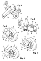
- the figure 1 has the right side part of a rear half-train having a suspension arm 2 disposed longitudinally on the side of the vehicle.
- the front of this suspension arm 2 comprises a ring 4 whose axis is arranged substantially transversely, this ring receiving an elastic block inserted into a yoke attached to the vehicle body, to achieve an elastic articulation filtering vibrations.
- the rear of the suspension arm 2 comprises a hub carrier 6, bearing by bearings a transverse axis receiving a rear wheel.
- a deformable cross member 8 has its ends fixed to the suspension arms 2 at a central point of these arms. This deformable cross member 8 maintains the geometry of the suspension arms 2, and constitutes a torsion spring which limits the difference in movement of these arms.
- the suspension arms 2 comprise at the rear, a substantially horizontal support 12 formed by a stamped sheet, receiving the lower end of a helical spring suspension.
- a hydraulic damper 10 comprising a sliding cylinder whose upper end is fixed to the vehicle body, passes on the outside of the suspension arm 2, just in front of the hub carrier 6.
- This hydraulic damper 10 comprises a ring having an internal rubber ring.
- a transverse axis passing through this ring is fixed on the suspension arm 2, to ensure an elastic connection.
- This transverse axis may comprise a fixing screw which is screwed into a hole of a cylindrical spacer welded to the side of the suspension arm 2.
- the hydraulic damper 10 whose body has a certain diameter, is sufficiently far from the suspension arm 2 that it runs to avoid contact during the movement of the suspension.
- the transverse axis of attachment of the base of the damper 10, can be mounted in a yoke, which complicates the realization of the rear axle.
- the transverse axis can also be mounted cantilever. This axis then working in bending, must have a large diameter to support the loads.
- the Figures 2 and 3 have for a rear axle 31, a suspension arm 20 having a longitudinal body 22 connecting the front ring 4 to a hub carrier 24, on which is welded the crossbar 8.
- the longitudinal body 22 comprises a stamped sheet metal in a substantially "U" -shaped section extending along this body.
- the "U" section of this body 22 has two wings laid flat, the open side of this section being turned towards the outside of the vehicle.
- the body 22 of the suspension arm 2 made of a single sheet is economical.
- the deformable cross member 8 is welded inwards on the closed side of the section.
- the wings of the "U" -shaped section of the body 22, each comprise, in front of the axis of the hub carrier 24, a bore aligned with one another forming a substantially vertical opening which passes through the suspension arm 20.
- This opening receives a reinforcing tube 30 passing right through the body 22 of the suspension arm 20, and protruding on each side, this tube being fitly mounted in the two bores of the wings of this body. Welds made on the edges of the bores of the two wings of the body 22, connect these wings to the reinforcing tube 30.
- a rigid assembly is thus produced, the reinforcement tube 30 welded to the two wings of the body 22 and connecting these two wings, providing a significant reinforcement of the suspension arm 20.
- the base of the reinforcing tube 30 comprises a cutout comprising two lower bosses, each containing a bore receiving a fastening screw 32 aligned along a transverse axis of the vehicle, which passes through this tube.
- the bosses form a clevis receiving inside the base of the damper 10, the fixing screw 32 passing through the lower ring of this damper which is supported on both sides by the reinforcing tube 30.
- the reinforcing tube 30 is made from a thin sheet which is rolled, which represents an economical process.
- the fixing screw 32 may have a reduced diameter and length compared to the cantilever mounting.
- the body 22 can be made more easily from a sheet metal reduced thickness, allowing lighter manufacturing with improved accuracy.
- the opening made on the wings of the body 22 of the suspension arm 20 has a longitudinally elongate shape.
- the fixing screw 32 is centered in the middle of this elongated shape, so as to dispose in the longitudinal direction, the base of the damper 10 substantially in the center of this opening when the suspension is at rest.
- the damper 10 can thus during movements of the suspension arm 20 during the movement of the suspensions, oscillate in the elongate opening relative to this arm, forwards or backwards.
- the longitudinal diameter of the reinforcing tube 30 can be reduced downwards and widen upwards, the section of the reinforcing tube 30 is thus reduced to the minimum necessary to ensure the movements of the damper 10.
- the figure 4 presents alternatively a rear axle 41, comprising a deformable cross member 42 comprising welded at its end, a half-front suspension arm 40 facing forward, which is connected to a rear half suspension arm 44 facing backwards.
- the longitudinal body of the rear half-arm 44 can in the same way, be made by a stamped sheet section of a substantially "U" whose opening is turned towards the outside of the vehicle.
- the wings of the "U" section of the half-rear arm 44 each comprise a hole forming a vertical opening which receives the reinforcing tube 30 passing through the suspension arm 20.
- FIG 5 presents for a second variant, a rear axle 51 comprising a deformable cross member 52 whose ends are bent backwards, to form two integrated half-suspension arms. At the curvature of this deformable cross member 52, a forward half suspension arm 40 is welded.
- the deformable crosspiece 52 comprising its end portions forming the rear half-arm, is formed by a stamped sheet metal section substantially "U" whose opening is turned towards the front of the vehicle.
- the wings of the "U" section of the rear half-arms receive in the same manner the reinforcing tube 30.
Landscapes
- Engineering & Computer Science (AREA)
- Mechanical Engineering (AREA)
- Vehicle Body Suspensions (AREA)
- Body Structure For Vehicles (AREA)
Claims (11)
- Hinterachse (31, 41, 51) für ein Kraftfahrzeug, umfassend zwei Aufhängungsarme (22, 44), die auf einer im Wesentlichen vertikalen Ebene um eine vorne angebrachte Achse schwingen, und umfassend jeweils hinter ihrem entsprechenden Arm einen Nabenträger (24), der ein Hinterrad (34) trägt, wobei die Achse außerdem einen verformbaren Querträger (8, 42, 52) umfasst, der die zwei Aufhängungsarme (22, 24) verbindet, wobei jeder Aufhängungsarm (22, 24) eine im Wesentlichen vertikale Öffnung mit einem festen Umriss umfasst, die sich in der Breite des Arms befindet, vor der Achse des Nabenträgers (24), zwischen dem Querträger (8, 42, 52) und dem Nabenträger (24), angeordnet ist und einen Dämpfer (10) aufnimmt, von dem eine untere Befestigung mit dem Aufhängungsarm (22, 44) verbunden ist, dadurch gekennzeichnet, dass die Öffnung von einer Seite zur anderen von dem Dämpfer (10) durchsetzt wird, wobei die untere Befestigung des Dämpfers (10) unter der Öffnung hervorsteht.
- Hinterachse (31, 41, 51) nach dem vorhergehenden Anspruch, dadurch gekennzeichnet, dass der Aufhängungsarm (22, 44) ein oberes Blech und ein unteres Blech umfasst, die jeweils eine Bohrung umfassen, die aufeinander ausgerichtet sind und die Öffnung bilden, wobei ein Verstärkungsrohr (30), das diese Öffnung durchsetzt, an diesen zwei Blechen befestigt ist.
- Hinterachse (31, 41, 51) nach dem vorhergehenden Anspruch, dadurch gekennzeichnet, dass die Basis des Verstärkungsrohrs (30) einen Ausschnitt umfasst, der zwei Bohrungen umfasst, die quer ausgerichtet sind und eine Klemmachse (32) aufnehmen, um eine Kappe zu bilden, die die untere Befestigung der Dämpfung (10) einfasst und sie mit dem Aufhängungsarm (22, 44) verbindet.
- Hinterachse (31, 41, 51) nach Anspruch 2 oder 3, dadurch gekennzeichnet, dass der Aufhängungsarm einen Längskörper (22, 44) umfasst, der durch ein tiefgezogenes Blech gemäß einem Abschnitt mit der allgemeinen Form eines U realisiert ist, der zwei Flügel umfasst, die im Wesentlichen flach bezüglich des oberen Blechs bzw. des unteren Blechs gelegt sind.
- Hinterachse (31, 41, 51) nach Anspruch 4, dadurch gekennzeichnet, dass das Verstärkungsrohr (30) auf dem Rand der Bohrungen der zwei Flügel des U-förmigen Abschnitts aufgeschweißt ist.
- Hinterachse (31, 41, 51) nach einem der Ansprüche 2 bis 5, dadurch gekennzeichnet, dass das Verstärkungsrohr (30) aus einem dünnen Blech hergestellt ist, das im Innern der Bohrungen gerollt ist.
- Hinterachse (31, 41, 51) nach einem der vorhergehenden Ansprüche, dadurch gekennzeichnet, dass die Öffnung, die auf dem Aufhängungsarm (22, 44) realisiert ist, eine gestreckte Längsform aufweist, wobei die untere Befestigung des Dämpfers (10) im Wesentlichen in der Länge dieser Öffnung zentriert ist.
- Hinterachse (31) nach einem der vorhergehenden Ansprüche, dadurch gekennzeichnet, dass der verformbare Querträger (8) mit seinen Enden an einem zentralen Teil der Aufhängungsarme (22) befestigt ist.
- Hinterachse (41) nach einem der Ansprüche 1 bis 7, dadurch gekennzeichnet, dass jeder Aufhängungsarm einen vorderen Halbarm (40) und einen hinteren Halbarm (44) aufweist, die direkt auf dem verformbaren Querträger (42) befestigt sind.
- Hinterachse (51) nach einem der Ansprüche 1 bis 7, dadurch gekennzeichnet, dass der verformbare Querträger (52) nach hinten gekrümmte Enden aufweist, die zwei integrierte hintere Aufhängungshalbarme bilden; wobei zwei vordere Aufhängungshalbarme (40), die nach vorne gedreht sind, auf diesem Querträger (52) befestigt sind.
- Kraftfahrzeug, umfassend eine Hinterachse (31, 41, 51) gemäß einem der vorhergehenden Ansprüche.
Applications Claiming Priority (2)
| Application Number | Priority Date | Filing Date | Title |
|---|---|---|---|
| FR0857982A FR2938794A1 (fr) | 2008-11-25 | 2008-11-25 | Train arriere pour vehicule automobile comprenant deux bras de suspension comportant une ouverture verticale |
| EP09176808A EP2189311B1 (de) | 2008-11-25 | 2009-11-23 | Hinterachse für Kraftfahrzeuge umfassend zwei Aufhängungsarme mit einer vertikalen Öffnung |
Related Parent Applications (1)
| Application Number | Title | Priority Date | Filing Date |
|---|---|---|---|
| EP09176808.5 Division | 2009-11-23 |
Publications (2)
| Publication Number | Publication Date |
|---|---|
| EP2199120A1 EP2199120A1 (de) | 2010-06-23 |
| EP2199120B1 true EP2199120B1 (de) | 2011-09-28 |
Family
ID=40756192
Family Applications (2)
| Application Number | Title | Priority Date | Filing Date |
|---|---|---|---|
| EP09176808A Not-in-force EP2189311B1 (de) | 2008-11-25 | 2009-11-23 | Hinterachse für Kraftfahrzeuge umfassend zwei Aufhängungsarme mit einer vertikalen Öffnung |
| EP10159217A Not-in-force EP2199120B1 (de) | 2008-11-25 | 2009-11-23 | Hinterachse eines Fahrzeuges mit zwei Aufhängungslenker mit senkrechter Öffnung |
Family Applications Before (1)
| Application Number | Title | Priority Date | Filing Date |
|---|---|---|---|
| EP09176808A Not-in-force EP2189311B1 (de) | 2008-11-25 | 2009-11-23 | Hinterachse für Kraftfahrzeuge umfassend zwei Aufhängungsarme mit einer vertikalen Öffnung |
Country Status (4)
| Country | Link |
|---|---|
| EP (2) | EP2189311B1 (de) |
| AT (1) | ATE526184T1 (de) |
| ES (2) | ES2369182T3 (de) |
| FR (1) | FR2938794A1 (de) |
Cited By (1)
| Publication number | Priority date | Publication date | Assignee | Title |
|---|---|---|---|---|
| US10228057B2 (en) | 2015-11-25 | 2019-03-12 | Caterpillar Inc. | Circumferential debris seal for pinned joints |
Families Citing this family (3)
| Publication number | Priority date | Publication date | Assignee | Title |
|---|---|---|---|---|
| US8991839B1 (en) * | 2014-05-19 | 2015-03-31 | Arvinmeritor Technology, Llc | Axle suspension system |
| FR3021585A1 (fr) * | 2014-05-27 | 2015-12-04 | Peugeot Citroen Automobiles Sa | Architecture de train arriere a traverse deformable dans un vehicule. |
| CN108859650B (zh) * | 2018-05-29 | 2020-01-24 | 安徽卓全汽车轮毂科技有限公司 | 一种扭力梁轮毂支架总成 |
Family Cites Families (8)
| Publication number | Priority date | Publication date | Assignee | Title |
|---|---|---|---|---|
| JPS58105815A (ja) * | 1981-12-17 | 1983-06-23 | Mazda Motor Corp | 自動車の後輪懸架装置 |
| FR2574347A1 (fr) * | 1984-12-12 | 1986-06-13 | Ford France | Suspension d'essieu arriere pour vehicule automobile |
| DE3832181A1 (de) * | 1988-09-22 | 1990-04-05 | Benteler Werke Ag | Aufhaengung fuer die hinterraeder eines kraftfahrzeugs |
| JP3526792B2 (ja) * | 1999-09-17 | 2004-05-17 | 本田技研工業株式会社 | トーションビーム式サスペンション |
| JP4089489B2 (ja) * | 2003-04-10 | 2008-05-28 | トヨタ自動車株式会社 | アクスルビーム |
| KR100530031B1 (ko) * | 2003-11-11 | 2005-11-21 | 현대모비스 주식회사 | 토션 빔 액슬 서스펜션 |
| US20070246904A1 (en) * | 2005-09-12 | 2007-10-25 | Satoshi Murata | Torsion-Beam-Type Suspension Apparatus |
| ITTO20060334A1 (it) * | 2006-05-09 | 2007-11-10 | Sistemi Sospensioni Spa | Braccio per una sospensione a ruote indipendenti per autoveicolo e sospensione a ruote indipendenti per autoveicolo comprendente un tale braccio |
-
2008
- 2008-11-25 FR FR0857982A patent/FR2938794A1/fr not_active Withdrawn
-
2009
- 2009-11-23 EP EP09176808A patent/EP2189311B1/de not_active Not-in-force
- 2009-11-23 ES ES10159217T patent/ES2369182T3/es active Active
- 2009-11-23 ES ES09176808T patent/ES2398481T3/es active Active
- 2009-11-23 EP EP10159217A patent/EP2199120B1/de not_active Not-in-force
- 2009-11-23 AT AT10159217T patent/ATE526184T1/de not_active IP Right Cessation
Cited By (1)
| Publication number | Priority date | Publication date | Assignee | Title |
|---|---|---|---|---|
| US10228057B2 (en) | 2015-11-25 | 2019-03-12 | Caterpillar Inc. | Circumferential debris seal for pinned joints |
Also Published As
| Publication number | Publication date |
|---|---|
| ES2398481T3 (es) | 2013-03-19 |
| FR2938794A1 (fr) | 2010-05-28 |
| ES2369182T3 (es) | 2011-11-28 |
| ATE526184T1 (de) | 2011-10-15 |
| EP2189311B1 (de) | 2013-01-02 |
| EP2199120A1 (de) | 2010-06-23 |
| EP2189311A1 (de) | 2010-05-26 |
Similar Documents
| Publication | Publication Date | Title |
|---|---|---|
| EP0679126B1 (de) | Fahrzeug-hinterradsatz mit einer halbsteifen achse | |
| EP2055614B1 (de) | Struktur eines Kraftfahrzeugs | |
| EP2050597A1 (de) | Befestigung eines Querstabilisators auf dem Zugverband eines Kraftfahrzeugs | |
| EP2189311B1 (de) | Hinterachse für Kraftfahrzeuge umfassend zwei Aufhängungsarme mit einer vertikalen Öffnung | |
| EP1827880B1 (de) | Flexible achse mit einem querträger mit trapezförmigem querschnitt, entsprechender querträger, fahrzeug und herstellungsverfahren | |
| FR3021585A1 (fr) | Architecture de train arriere a traverse deformable dans un vehicule. | |
| EP2019023A1 (de) | Hinterachslenkung für Autos, die ein deformierbares Radachsengelenk umfasst | |
| EP0389363B1 (de) | Kraftfahrzeughinterradsatz | |
| FR2761304A1 (fr) | Train de roues arriere pour vehicule automobile a traverse deformable en torsion | |
| EP1240039B1 (de) | Hinterachse mit einem geschweiften querträger | |
| EP1689598B1 (de) | Flexible achse mit einer quersteifigkeit, die mit hilfe von mindestens einem federtellerformteil erhöht wird, federteller und entsprechendes fahrzeug | |
| EP3119665B1 (de) | Heckstruktur eines kraftfahrzeugs | |
| EP2075146B1 (de) | Verbundlenkerachse und Verfahren zur Herstellung eines Querträgers | |
| WO2010058133A1 (fr) | Bras de suspension monobloc de vehicule automobile | |
| WO2011148097A1 (fr) | Ensemble pour vehicule automobile, comprenant un chassis arriere supportant un groupe motopropulseur | |
| WO1998043840A1 (fr) | Perfectionnement a un essieu arriere pour vehicule automobile du type a traverse deformable en torsion et a ressorts de suspension sensiblement verticaux | |
| EP2213487A1 (de) | Hinterradaufhängung für ein Kraftfahrzeug mit zwei seitlichen Federn aus Verbundmaterial | |
| FR2941405A1 (fr) | Barre anti-roulis pour vehicule automobile, comportant une partie centrale de torsion. | |
| FR2833529A1 (fr) | Essieu souple pour roues non motrices d'un vehicle automobile | |
| FR2959449A1 (fr) | Train arriere du type semi-rigide pour vehicule automobile | |
| US20110272912A1 (en) | Motor vehicle rear train having a two arm suspension with a vertical opening | |
| EP3317131A1 (de) | Aufhängungsvorrichtung für ein kraftfahrzeugrad mit einem arm mit einem blechkörper und einem daran befestigten massiven kopf | |
| FR2963754A1 (fr) | Essieu arriere pour vehicule automobile | |
| EP3684635A1 (de) | Querträgersystem für ein kraftfahrzeug, das einen querführungsstab aufnimmt | |
| FR3070142B1 (fr) | Systeme de traverse de vehicule automobile avec des inserts pour une barre de guidage transversal |
Legal Events
| Date | Code | Title | Description |
|---|---|---|---|
| PUAI | Public reference made under article 153(3) epc to a published international application that has entered the european phase |
Free format text: ORIGINAL CODE: 0009012 |
|
| AC | Divisional application: reference to earlier application |
Ref document number: 2189311 Country of ref document: EP Kind code of ref document: P |
|
| AK | Designated contracting states |
Kind code of ref document: A1 Designated state(s): AT BE BG CH CY CZ DE DK EE ES FI FR GB GR HR HU IE IS IT LI LT LU LV MC MK MT NL NO PL PT RO SE SI SK SM TR |
|
| AX | Request for extension of the european patent |
Extension state: AL BA RS |
|
| 17P | Request for examination filed |
Effective date: 20110203 |
|
| GRAP | Despatch of communication of intention to grant a patent |
Free format text: ORIGINAL CODE: EPIDOSNIGR1 |
|
| RIC1 | Information provided on ipc code assigned before grant |
Ipc: B60G 21/05 20060101ALI20110512BHEP Ipc: B60G 13/00 20060101AFI20110512BHEP |
|
| GRAS | Grant fee paid |
Free format text: ORIGINAL CODE: EPIDOSNIGR3 |
|
| GRAA | (expected) grant |
Free format text: ORIGINAL CODE: 0009210 |
|
| AC | Divisional application: reference to earlier application |
Ref document number: 2189311 Country of ref document: EP Kind code of ref document: P |
|
| AK | Designated contracting states |
Kind code of ref document: B1 Designated state(s): AT BE BG CH CY CZ DE DK EE ES FI FR GB GR HR HU IE IS IT LI LT LU LV MC MK MT NL NO PL PT RO SE SI SK SM TR |
|
| REG | Reference to a national code |
Ref country code: GB Ref legal event code: FG4D Free format text: NOT ENGLISH |
|
| REG | Reference to a national code |
Ref country code: CH Ref legal event code: EP |
|
| REG | Reference to a national code |
Ref country code: IE Ref legal event code: FG4D |
|
| REG | Reference to a national code |
Ref country code: DE Ref legal event code: R084 Ref document number: 602009002886 Country of ref document: DE |
|
| REG | Reference to a national code |
Ref country code: ES Ref legal event code: FG2A Ref document number: 2369182 Country of ref document: ES Kind code of ref document: T3 Effective date: 20111128 |
|
| REG | Reference to a national code |
Ref country code: DE Ref legal event code: R096 Ref document number: 602009002886 Country of ref document: DE Effective date: 20111201 |
|
| REG | Reference to a national code |
Ref country code: GB Ref legal event code: 746 Effective date: 20111128 |
|
| REG | Reference to a national code |
Ref country code: NL Ref legal event code: VDEP Effective date: 20110928 |
|
| REG | Reference to a national code |
Ref country code: DE Ref legal event code: R084 Ref document number: 602009002886 Country of ref document: DE Effective date: 20111119 |
|
| PG25 | Lapsed in a contracting state [announced via postgrant information from national office to epo] |
Ref country code: SE Free format text: LAPSE BECAUSE OF FAILURE TO SUBMIT A TRANSLATION OF THE DESCRIPTION OR TO PAY THE FEE WITHIN THE PRESCRIBED TIME-LIMIT Effective date: 20110928 Ref country code: FI Free format text: LAPSE BECAUSE OF FAILURE TO SUBMIT A TRANSLATION OF THE DESCRIPTION OR TO PAY THE FEE WITHIN THE PRESCRIBED TIME-LIMIT Effective date: 20110928 Ref country code: LT Free format text: LAPSE BECAUSE OF FAILURE TO SUBMIT A TRANSLATION OF THE DESCRIPTION OR TO PAY THE FEE WITHIN THE PRESCRIBED TIME-LIMIT Effective date: 20110928 Ref country code: HR Free format text: LAPSE BECAUSE OF FAILURE TO SUBMIT A TRANSLATION OF THE DESCRIPTION OR TO PAY THE FEE WITHIN THE PRESCRIBED TIME-LIMIT Effective date: 20110928 Ref country code: NO Free format text: LAPSE BECAUSE OF FAILURE TO SUBMIT A TRANSLATION OF THE DESCRIPTION OR TO PAY THE FEE WITHIN THE PRESCRIBED TIME-LIMIT Effective date: 20111228 |
|
| LTIE | Lt: invalidation of european patent or patent extension |
Effective date: 20110928 |
|
| PG25 | Lapsed in a contracting state [announced via postgrant information from national office to epo] |
Ref country code: SI Free format text: LAPSE BECAUSE OF FAILURE TO SUBMIT A TRANSLATION OF THE DESCRIPTION OR TO PAY THE FEE WITHIN THE PRESCRIBED TIME-LIMIT Effective date: 20110928 Ref country code: CY Free format text: LAPSE BECAUSE OF FAILURE TO SUBMIT A TRANSLATION OF THE DESCRIPTION OR TO PAY THE FEE WITHIN THE PRESCRIBED TIME-LIMIT Effective date: 20110928 Ref country code: AT Free format text: LAPSE BECAUSE OF FAILURE TO SUBMIT A TRANSLATION OF THE DESCRIPTION OR TO PAY THE FEE WITHIN THE PRESCRIBED TIME-LIMIT Effective date: 20110928 Ref country code: LV Free format text: LAPSE BECAUSE OF FAILURE TO SUBMIT A TRANSLATION OF THE DESCRIPTION OR TO PAY THE FEE WITHIN THE PRESCRIBED TIME-LIMIT Effective date: 20110928 Ref country code: GR Free format text: LAPSE BECAUSE OF FAILURE TO SUBMIT A TRANSLATION OF THE DESCRIPTION OR TO PAY THE FEE WITHIN THE PRESCRIBED TIME-LIMIT Effective date: 20111229 |
|
| REG | Reference to a national code |
Ref country code: AT Ref legal event code: MK05 Ref document number: 526184 Country of ref document: AT Kind code of ref document: T Effective date: 20110928 |
|
| REG | Reference to a national code |
Ref country code: IE Ref legal event code: FD4D |
|
| PG25 | Lapsed in a contracting state [announced via postgrant information from national office to epo] |
Ref country code: IS Free format text: LAPSE BECAUSE OF FAILURE TO SUBMIT A TRANSLATION OF THE DESCRIPTION OR TO PAY THE FEE WITHIN THE PRESCRIBED TIME-LIMIT Effective date: 20120128 Ref country code: CZ Free format text: LAPSE BECAUSE OF FAILURE TO SUBMIT A TRANSLATION OF THE DESCRIPTION OR TO PAY THE FEE WITHIN THE PRESCRIBED TIME-LIMIT Effective date: 20110928 Ref country code: SK Free format text: LAPSE BECAUSE OF FAILURE TO SUBMIT A TRANSLATION OF THE DESCRIPTION OR TO PAY THE FEE WITHIN THE PRESCRIBED TIME-LIMIT Effective date: 20110928 |
|
| BERE | Be: lapsed |
Owner name: PEUGEOT CITROEN AUTOMOBILES SA Effective date: 20111130 |
|
| PG25 | Lapsed in a contracting state [announced via postgrant information from national office to epo] |
Ref country code: RO Free format text: LAPSE BECAUSE OF FAILURE TO SUBMIT A TRANSLATION OF THE DESCRIPTION OR TO PAY THE FEE WITHIN THE PRESCRIBED TIME-LIMIT Effective date: 20110928 Ref country code: EE Free format text: LAPSE BECAUSE OF FAILURE TO SUBMIT A TRANSLATION OF THE DESCRIPTION OR TO PAY THE FEE WITHIN THE PRESCRIBED TIME-LIMIT Effective date: 20110928 Ref country code: PT Free format text: LAPSE BECAUSE OF FAILURE TO SUBMIT A TRANSLATION OF THE DESCRIPTION OR TO PAY THE FEE WITHIN THE PRESCRIBED TIME-LIMIT Effective date: 20120130 Ref country code: NL Free format text: LAPSE BECAUSE OF FAILURE TO SUBMIT A TRANSLATION OF THE DESCRIPTION OR TO PAY THE FEE WITHIN THE PRESCRIBED TIME-LIMIT Effective date: 20110928 |
|
| PG25 | Lapsed in a contracting state [announced via postgrant information from national office to epo] |
Ref country code: MC Free format text: LAPSE BECAUSE OF NON-PAYMENT OF DUE FEES Effective date: 20111130 |
|
| PG25 | Lapsed in a contracting state [announced via postgrant information from national office to epo] |
Ref country code: IE Free format text: LAPSE BECAUSE OF FAILURE TO SUBMIT A TRANSLATION OF THE DESCRIPTION OR TO PAY THE FEE WITHIN THE PRESCRIBED TIME-LIMIT Effective date: 20110928 Ref country code: DK Free format text: LAPSE BECAUSE OF FAILURE TO SUBMIT A TRANSLATION OF THE DESCRIPTION OR TO PAY THE FEE WITHIN THE PRESCRIBED TIME-LIMIT Effective date: 20110928 |
|
| PLBE | No opposition filed within time limit |
Free format text: ORIGINAL CODE: 0009261 |
|
| STAA | Information on the status of an ep patent application or granted ep patent |
Free format text: STATUS: NO OPPOSITION FILED WITHIN TIME LIMIT |
|
| PG25 | Lapsed in a contracting state [announced via postgrant information from national office to epo] |
Ref country code: BE Free format text: LAPSE BECAUSE OF NON-PAYMENT OF DUE FEES Effective date: 20111130 Ref country code: PL Free format text: LAPSE BECAUSE OF FAILURE TO SUBMIT A TRANSLATION OF THE DESCRIPTION OR TO PAY THE FEE WITHIN THE PRESCRIBED TIME-LIMIT Effective date: 20110928 |
|
| 26N | No opposition filed |
Effective date: 20120629 |
|
| REG | Reference to a national code |
Ref country code: DE Ref legal event code: R097 Ref document number: 602009002886 Country of ref document: DE Effective date: 20120629 |
|
| PG25 | Lapsed in a contracting state [announced via postgrant information from national office to epo] |
Ref country code: MK Free format text: LAPSE BECAUSE OF FAILURE TO SUBMIT A TRANSLATION OF THE DESCRIPTION OR TO PAY THE FEE WITHIN THE PRESCRIBED TIME-LIMIT Effective date: 20110928 Ref country code: MT Free format text: LAPSE BECAUSE OF FAILURE TO SUBMIT A TRANSLATION OF THE DESCRIPTION OR TO PAY THE FEE WITHIN THE PRESCRIBED TIME-LIMIT Effective date: 20110928 |
|
| PG25 | Lapsed in a contracting state [announced via postgrant information from national office to epo] |
Ref country code: SM Free format text: LAPSE BECAUSE OF FAILURE TO SUBMIT A TRANSLATION OF THE DESCRIPTION OR TO PAY THE FEE WITHIN THE PRESCRIBED TIME-LIMIT Effective date: 20110928 |
|
| PG25 | Lapsed in a contracting state [announced via postgrant information from national office to epo] |
Ref country code: LU Free format text: LAPSE BECAUSE OF NON-PAYMENT OF DUE FEES Effective date: 20111123 |
|
| PG25 | Lapsed in a contracting state [announced via postgrant information from national office to epo] |
Ref country code: BG Free format text: LAPSE BECAUSE OF FAILURE TO SUBMIT A TRANSLATION OF THE DESCRIPTION OR TO PAY THE FEE WITHIN THE PRESCRIBED TIME-LIMIT Effective date: 20111228 |
|
| PG25 | Lapsed in a contracting state [announced via postgrant information from national office to epo] |
Ref country code: TR Free format text: LAPSE BECAUSE OF FAILURE TO SUBMIT A TRANSLATION OF THE DESCRIPTION OR TO PAY THE FEE WITHIN THE PRESCRIBED TIME-LIMIT Effective date: 20110928 |
|
| PG25 | Lapsed in a contracting state [announced via postgrant information from national office to epo] |
Ref country code: HU Free format text: LAPSE BECAUSE OF FAILURE TO SUBMIT A TRANSLATION OF THE DESCRIPTION OR TO PAY THE FEE WITHIN THE PRESCRIBED TIME-LIMIT Effective date: 20110928 |
|
| REG | Reference to a national code |
Ref country code: CH Ref legal event code: PL |
|
| PG25 | Lapsed in a contracting state [announced via postgrant information from national office to epo] |
Ref country code: CH Free format text: LAPSE BECAUSE OF NON-PAYMENT OF DUE FEES Effective date: 20131130 Ref country code: LI Free format text: LAPSE BECAUSE OF NON-PAYMENT OF DUE FEES Effective date: 20131130 |
|
| REG | Reference to a national code |
Ref country code: FR Ref legal event code: PLFP Year of fee payment: 7 |
|
| REG | Reference to a national code |
Ref country code: FR Ref legal event code: PLFP Year of fee payment: 8 |
|
| REG | Reference to a national code |
Ref country code: ES Ref legal event code: GC2A Effective date: 20170116 |
|
| REG | Reference to a national code |
Ref country code: FR Ref legal event code: PLFP Year of fee payment: 9 |
|
| REG | Reference to a national code |
Ref country code: FR Ref legal event code: CA Effective date: 20180312 Ref country code: FR Ref legal event code: CD Owner name: PEUGEOT CITROEN AUTOMOBILES SA, FR Effective date: 20180312 |
|
| REG | Reference to a national code |
Ref country code: FR Ref legal event code: PLFP Year of fee payment: 10 |
|
| PGFP | Annual fee paid to national office [announced via postgrant information from national office to epo] |
Ref country code: GB Payment date: 20221021 Year of fee payment: 14 |
|
| PGFP | Annual fee paid to national office [announced via postgrant information from national office to epo] |
Ref country code: ES Payment date: 20231201 Year of fee payment: 15 |
|
| PGFP | Annual fee paid to national office [announced via postgrant information from national office to epo] |
Ref country code: IT Payment date: 20231019 Year of fee payment: 15 Ref country code: FR Payment date: 20231019 Year of fee payment: 15 Ref country code: DE Payment date: 20231019 Year of fee payment: 15 |
|
| GBPC | Gb: european patent ceased through non-payment of renewal fee |
Effective date: 20231123 |
|
| PG25 | Lapsed in a contracting state [announced via postgrant information from national office to epo] |
Ref country code: GB Free format text: LAPSE BECAUSE OF NON-PAYMENT OF DUE FEES Effective date: 20231123 |
|
| PG25 | Lapsed in a contracting state [announced via postgrant information from national office to epo] |
Ref country code: GB Free format text: LAPSE BECAUSE OF NON-PAYMENT OF DUE FEES Effective date: 20231123 |
|
| REG | Reference to a national code |
Ref country code: DE Ref legal event code: R119 Ref document number: 602009002886 Country of ref document: DE |
|
| PG25 | Lapsed in a contracting state [announced via postgrant information from national office to epo] |
Ref country code: DE Free format text: LAPSE BECAUSE OF NON-PAYMENT OF DUE FEES Effective date: 20250603 |
|
| PG25 | Lapsed in a contracting state [announced via postgrant information from national office to epo] |
Ref country code: IT Free format text: LAPSE BECAUSE OF NON-PAYMENT OF DUE FEES Effective date: 20241123 |
|
| PG25 | Lapsed in a contracting state [announced via postgrant information from national office to epo] |
Ref country code: FR Free format text: LAPSE BECAUSE OF NON-PAYMENT OF DUE FEES Effective date: 20241130 |
|
| REG | Reference to a national code |
Ref country code: ES Ref legal event code: FD2A Effective date: 20260107 |
|
| PG25 | Lapsed in a contracting state [announced via postgrant information from national office to epo] |
Ref country code: ES Free format text: LAPSE BECAUSE OF NON-PAYMENT OF DUE FEES Effective date: 20241124 |