EP2199209A1 - Dispositif de remplissage de produits pharmaceutiques dans des récipients d'emballage - Google Patents
Dispositif de remplissage de produits pharmaceutiques dans des récipients d'emballage Download PDFInfo
- Publication number
- EP2199209A1 EP2199209A1 EP08172610A EP08172610A EP2199209A1 EP 2199209 A1 EP2199209 A1 EP 2199209A1 EP 08172610 A EP08172610 A EP 08172610A EP 08172610 A EP08172610 A EP 08172610A EP 2199209 A1 EP2199209 A1 EP 2199209A1
- Authority
- EP
- European Patent Office
- Prior art keywords
- region
- pharmaceutical products
- guide channel
- filling
- reservoir
- Prior art date
- Legal status (The legal status is an assumption and is not a legal conclusion. Google has not performed a legal analysis and makes no representation as to the accuracy of the status listed.)
- Granted
Links
- 239000000825 pharmaceutical preparation Substances 0.000 title claims abstract description 31
- 229940127557 pharmaceutical product Drugs 0.000 title claims abstract description 31
- 238000004806 packaging method and process Methods 0.000 title claims abstract description 22
- 230000005484 gravity Effects 0.000 claims abstract description 4
- 238000010276 construction Methods 0.000 description 5
- 230000015556 catabolic process Effects 0.000 description 2
- 230000006378 damage Effects 0.000 description 2
- 238000006731 degradation reaction Methods 0.000 description 2
- 230000005686 electrostatic field Effects 0.000 description 2
- 238000004519 manufacturing process Methods 0.000 description 2
- 230000015572 biosynthetic process Effects 0.000 description 1
- 230000003139 buffering effect Effects 0.000 description 1
- 239000002775 capsule Substances 0.000 description 1
- 239000008298 dragée Substances 0.000 description 1
- 238000003780 insertion Methods 0.000 description 1
- 230000037431 insertion Effects 0.000 description 1
- 239000011159 matrix material Substances 0.000 description 1
- 239000002184 metal Substances 0.000 description 1
- 229910001220 stainless steel Inorganic materials 0.000 description 1
- 239000010935 stainless steel Substances 0.000 description 1
- 239000003826 tablet Substances 0.000 description 1
- 230000007704 transition Effects 0.000 description 1
- 239000013585 weight reducing agent Substances 0.000 description 1
Images


Classifications
-
- B—PERFORMING OPERATIONS; TRANSPORTING
- B65—CONVEYING; PACKING; STORING; HANDLING THIN OR FILAMENTARY MATERIAL
- B65B—MACHINES, APPARATUS OR DEVICES FOR, OR METHODS OF, PACKAGING ARTICLES OR MATERIALS; UNPACKING
- B65B5/00—Packaging individual articles in containers or receptacles, e.g. bags, sacks, boxes, cartons, cans, jars
- B65B5/10—Filling containers or receptacles progressively or in stages by introducing successive articles, or layers of articles
- B65B5/101—Filling containers or receptacles progressively or in stages by introducing successive articles, or layers of articles by gravity
- B65B5/103—Filling containers or receptacles progressively or in stages by introducing successive articles, or layers of articles by gravity for packaging pills or tablets
-
- B—PERFORMING OPERATIONS; TRANSPORTING
- B65—CONVEYING; PACKING; STORING; HANDLING THIN OR FILAMENTARY MATERIAL
- B65B—MACHINES, APPARATUS OR DEVICES FOR, OR METHODS OF, PACKAGING ARTICLES OR MATERIALS; UNPACKING
- B65B35/00—Supplying, feeding, arranging or orientating articles to be packaged
- B65B35/10—Feeding, e.g. conveying, single articles
- B65B35/12—Feeding, e.g. conveying, single articles by gravity
-
- B—PERFORMING OPERATIONS; TRANSPORTING
- B65—CONVEYING; PACKING; STORING; HANDLING THIN OR FILAMENTARY MATERIAL
- B65B—MACHINES, APPARATUS OR DEVICES FOR, OR METHODS OF, PACKAGING ARTICLES OR MATERIALS; UNPACKING
- B65B39/00—Nozzles, funnels or guides for introducing articles or materials into containers or wrappers
- B65B39/007—Guides or funnels for introducing articles into containers or wrappers
Definitions
- the present invention relates to a device for filling pharmaceutical products into packaging containers.
- Such a device is for example off US 5,737,902 known.
- the device described therein comprises a reservoir for pharmaceutical products and a supply device with at least one guide channel for conducting the pharmaceutical products by means of their gravity from the reservoir into the packaging container.
- the reservoir is usually moved up and down to dispense the pharmaceutical products individually in the guide channel, in which the pharmaceutical products are stacked on each other and gradually discharged down into a filling trough.
- the filling trough directs the initially vertically oriented tablets in the direction of a horizontal position and passes the tablets into the packaging containers, for example cups of a blister package.
- the guide channel can in the upper area instead of the gradual lowering of the tablets by means of laterally movable stacking floors, as in US 5,737,902 also have elaborate designs for separating and conveying the tablets.
- certain geometries of the guide channel have been proposed, for example a spiral shape, see EP 1 391 386 A2 , as well as a zigzag shape with three-dimensional component, see EP 1 698 554 A1 ,
- plastic parts are preferably used to make the device inexpensive and lightweight. This can lead to the generation of unwanted electrostatic charge in some areas, which hinders the function of the filling device.
- electrostatic charge is generated, whereby an electrostatic field of significant strength can arise, which blocks the pharmaceutical products in the delivery tube.
- the device for filling pharmaceutical products into packaging containers has a storage container for the pharmaceutical products and a supply device with at least one guide channel for conducting the pharmaceutical products by means of their gravity from the storage container into the packaging containers.
- at least one high-voltage ionizer element supplied with alternating voltage is arranged in the region of the at least one guide channel.
- the degradation of the electrostatic charge is particularly high when the at least one high-voltage ionizer element at least partially surrounds the at least one guide channel.
- a particularly simple construction which is also applicable to a plurality of guide channels, is present when the at least one high-voltage ionizer element is designed as a plate or strip.
- the plate or strip extends horizontally so that it can be easily integrated into the device.
- the degradation of the electrostatic charge is additionally reinforced by the fact that at least one grounding element is arranged in the region of the at least one guide channel.
- the grounding element is preferably also designed as a horizontally oriented plate or bar.
- each guide channel has an upper segment, which is formed by a delivery tube.
- a high-voltage ionizer element may already be arranged in the region of the at least one delivery tube to provide for the removal of electrostatic charges generated by the up and down movement of the reservoir during insertion of the tablets into the guide channel.
- the high-voltage ionizer element is arranged in an upper region of the delivery tube and the grounding element is arranged below the high-voltage ionizer element.
- each guide channel has a lower segment, which is formed by a filling channel.
- a high-voltage ionizer element in the region of the filling channel, in particular in a lower section of the filling channel with a horizontal component. This ensures that the electrostatic charges generated during the deflection of the tablets within the filling channel are eliminated before the final delivery of the tablets into the packaging containers and thus the filling can take place unhindered.
- the grounding element is arranged above the high-voltage ionizer element, because this results in a two-sided electric charge destruction, because even the table top over which the packaging container are pulled, acts as a grounded element.
- Fig. 1 shows a first embodiment of the device according to the invention for filling pharmaceutical products, such as tablets, dragees, capsules, etc. in packaging containers.
- the device comprises a reservoir 2, in which the pharmaceutical products are stored before filling.
- the reservoir 2 has one or more trough-shaped recesses which are filled with the pharmaceutical products 4.
- an opening 6 is arranged, which leads to a feed device with a guide channel 8, which is intended to guide the pharmaceutical products 4 into the packaging containers 10.
- the packaging containers 10 are usually clocked by means of a transport device (not shown) passed over a table top 12 at the filling station in the direction of arrow A. Likewise, a movement of the packaging container 10 from the drawing level is possible.
- the packaging container 10 as wells of a Formed blister, which is sealed after filling with the pharmaceutical products 4 with a cover sheet and then punched out of the individual blister packs. But there are also many other applications conceivable that lie outside the pharmaceutical sector.
- Each guide channel 8 has an upper segment 14 and a lower segment 16 in the illustrated example case.
- the guide channel 8 may also be designed in one piece in specific embodiments and comprise only one segment.
- the upper segment 14 is formed in this example as a delivery tube, which projects with its upper portion in an opening 6 of the reservoir 2.
- the reservoir 2 is in accordance with arrow B in Fig. 2 movable up and down.
- the left part of the reservoir 2 is in Fig. 2 shown in the raised position, while the right adjoining part of the reservoir 2 is shown in the lowered position.
- the delivery tubes 14 protrude differently far into the storage container 2 and thus a supply of individual pharmaceutical products 4 into the delivery tube 14 is made possible.
- a multiplicity of delivery tubes 14 are present in a type of matrix arrangement and are connected to the storage container 2 in order to simultaneously transport a plurality of pharmaceutical products 4 to the packaging containers 10 and to be able to fill them with them.
- both the reservoir 2 and the delivery tube 14 are formed from plastic.
- electrostatic charges 18 can be generated in the region of the opening 6, which can hinder the introduction of the pharmaceutical products 4 in the delivery tube 14.
- the device according to the invention has a high-voltage ionizer element 20 in the region of the delivery tube 14, preferably in its upper region. This preferably extends directly below the storage container 2 over its entire width and may preferably be formed as an electrically conductive plate, for example made of metal or metallized plastic, preferably made of stainless steel, which has corresponding openings for the delivery tube 14. Particularly preferred is a direct attachment of the plate at the bottom of the reservoir 2.
- the high-voltage ionizer 20 is preferably connected to an AC voltage source 22, by means of a flexible conduit which does not hinder the movement of the reservoir 2.
- the AC voltage source 22 preferably supplies the high-voltage ionizer element 20 with alternating voltage of a frequency of 50 Hz to 60 Hz and a height of 4 kV to 8 kV.
- the high voltage terminal also includes corresponding high voltage resistors for current limiting and safety warranty.
- each individual delivery tube 14 with a localized high voltage ionizer element 20 or to provide a different geometric arrangement of the high voltage ionizer elements 20. There are various geometric shapes conceivable here.
- a grounding element 24 is arranged below the high-voltage ionizer element 20, which is connected to earth 26 via a flexible line and is preferably also formed as a metallically conductive plate with openings for the delivery tube 14. Also, the grounding element can be present in a variety of geometric configurations.
- the delivery tube 14 may also define a helical guide channel or a zigzag conveying channel with three-dimensional component in addition to the illustrated straight configuration.
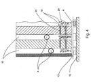
- FIG. 3 and 4 A second alternative embodiment of the present invention is shown.
- a Hochwoodslonisatorelement 20 and a grounding element 24 are arranged in the lower segment 16 of each filling channel 8.
- This application is particularly advantageous when the lower segment 16 is designed as a filling channel which has a curvature in its lower region for effecting a rotation of the pharmaceutical products 4.
- the Gresen 16 which are preferably all integrated into a filling shoe made of plastic, occurs here due to the sliding friction of the pharmaceutical products 4 on the inside of the filling grooves 16 in the curvature region an electrostatic charge, which in turn can hinder the filling of the packaging container 10 with the pharmaceutical products 4.
- an embodiment of the high-voltage ionizer 20 and the grounding element 24 is preferred as a bar, which may be provided for the Grerinnen 16 recesses in the bar. It can also be provided several strips. There are many possibilities with regard to the geometry of the arrangement. In this embodiment, however, it is advantageous if the high-voltage ionizer element 20 is arranged in a lower region of the filling channels 16 and the grounding element 24 is arranged above the high-voltage ionizer element 20. In this way, a two-sided charge removal is ensured starting from the high-voltage ionizer element up and down.
Landscapes
- Engineering & Computer Science (AREA)
- Mechanical Engineering (AREA)
- Basic Packing Technique (AREA)
- Medical Preparation Storing Or Oral Administration Devices (AREA)
Priority Applications (2)
| Application Number | Priority Date | Filing Date | Title |
|---|---|---|---|
| EP20080172610 EP2199209B1 (fr) | 2008-12-22 | 2008-12-22 | Dispositif de remplissage de produits pharmaceutiques dans des récipients d'emballage |
| US12/638,666 US8826631B2 (en) | 2008-12-22 | 2009-12-15 | Device for filling packaging receptacles with pharmaceutical products |
Applications Claiming Priority (1)
| Application Number | Priority Date | Filing Date | Title |
|---|---|---|---|
| EP20080172610 EP2199209B1 (fr) | 2008-12-22 | 2008-12-22 | Dispositif de remplissage de produits pharmaceutiques dans des récipients d'emballage |
Publications (2)
| Publication Number | Publication Date |
|---|---|
| EP2199209A1 true EP2199209A1 (fr) | 2010-06-23 |
| EP2199209B1 EP2199209B1 (fr) | 2011-06-15 |
Family
ID=40589872
Family Applications (1)
| Application Number | Title | Priority Date | Filing Date |
|---|---|---|---|
| EP20080172610 Not-in-force EP2199209B1 (fr) | 2008-12-22 | 2008-12-22 | Dispositif de remplissage de produits pharmaceutiques dans des récipients d'emballage |
Country Status (2)
| Country | Link |
|---|---|
| US (1) | US8826631B2 (fr) |
| EP (1) | EP2199209B1 (fr) |
Cited By (2)
| Publication number | Priority date | Publication date | Assignee | Title |
|---|---|---|---|---|
| EP3018058A1 (fr) * | 2014-11-04 | 2016-05-11 | UHLMANN PAC-SYSTEME GmbH & Co. KG | Dispositif de remplissage pour des bandes d'emballage transparent |
| DE102020111519A1 (de) | 2020-04-28 | 2021-10-28 | Jdm Innovation Gmbh | Vorrichtung zur Ausgabe von in Blisterbeuteln angeordneten Arzneimitteln und Betriebsverfahren hierfür |
Families Citing this family (5)
| Publication number | Priority date | Publication date | Assignee | Title |
|---|---|---|---|---|
| ITBO20110708A1 (it) * | 2011-12-14 | 2013-06-15 | Marchesini Group Spa | Apparato per regolare il rilascio di compresse negli alveoli di un nastro termoformato |
| AU2013224673B2 (en) * | 2012-09-07 | 2019-01-03 | Meditab Software Inc. | Medication dosage dispensing system and methods having customization and modification for medicine dispensing configurations |
| FR3017377B1 (fr) * | 2014-02-12 | 2017-01-13 | Stiplastics | Dispositif de comptage et de distribution d'objets |
| US20220380127A1 (en) * | 2021-05-27 | 2022-12-01 | Express Scripts Strategic Development, Inc. | Pharmaceutical order processing systems and methods |
| US20240238162A1 (en) * | 2021-08-27 | 2024-07-18 | Multiply Labs Inc. | System, method, and apparatus facilitating assembly of a capsule |
Citations (4)
| Publication number | Priority date | Publication date | Assignee | Title |
|---|---|---|---|---|
| US2595226A (en) * | 1948-01-22 | 1952-05-06 | Upjohn Co | Conveyer having dust separating and removal means |
| US5737902A (en) | 1996-09-19 | 1998-04-14 | Aylward Enterprises, Inc. | Apparatus and method for packaging pills |
| EP1391386A2 (fr) | 2002-08-21 | 2004-02-25 | Aylward Enterprises, Inc. | Procédé et appareil pour alimenter un récipient avec des pilules |
| EP1698554A1 (fr) | 2005-03-02 | 2006-09-06 | UHLMANN PAC-SYSTEME GmbH & Co. KG | Tube d'alimentation pour comprimés |
Family Cites Families (26)
| Publication number | Priority date | Publication date | Assignee | Title |
|---|---|---|---|---|
| US3024582A (en) * | 1960-11-09 | 1962-03-13 | Leland H Merrill | Capsule finishing and inspecting machine |
| US3768227A (en) * | 1970-09-16 | 1973-10-30 | R Grisell | Method of dissipating static electricity in packaging |
| US4007576A (en) * | 1975-06-19 | 1977-02-15 | Hercules Incorporated | Method and apparatus for controlling static charges |
| US5040353A (en) * | 1990-07-26 | 1991-08-20 | Glaxo Inc. | System for inspecting and recycling goods from defective packages on a blister packaging machine |
| JP2544052B2 (ja) * | 1991-12-18 | 1996-10-16 | 日本エランコ株式会社 | 硬質ゼラチンカプセルへの錠剤充填装置 |
| US5369940A (en) * | 1993-01-27 | 1994-12-06 | Pfizer Inc | Automatic filling system |
| US5522512A (en) * | 1994-05-09 | 1996-06-04 | Merck & Co., Inc. | System and method for automatically feeding, inspecting and diverting tablets for continuous filling of tablet containers |
| IT1278210B1 (it) * | 1995-05-19 | 1997-11-17 | Ima Spa | Macchina automatica per il confezionamento di compresse entro capsule di gelatina |
| US5922030A (en) * | 1995-12-20 | 1999-07-13 | Nartron Corporation | Method and system for controlling a solid product release mechanism |
| JP4153061B2 (ja) * | 1997-10-23 | 2008-09-17 | 株式会社湯山製作所 | 錠剤包装装置 |
| US5960609A (en) * | 1998-06-12 | 1999-10-05 | Microdose Technologies, Inc. | Metering and packaging method and device for pharmaceuticals and drugs |
| US6324253B1 (en) * | 1998-08-26 | 2001-11-27 | Yuyama Mfg. Co., Ltd. | Tablet inspection apparatus |
| DE29919756U1 (de) * | 1999-11-10 | 2001-03-22 | Electro-Mec (Reading) Ltd., Reading | Verpackungsvorrichtung |
| US6985798B2 (en) * | 2002-05-10 | 2006-01-10 | Oriel Therapeutics, Inc. | Dry powder dose filling systems and related methods |
| ITBO20020313A1 (it) * | 2002-05-21 | 2003-11-21 | Ima Spa | Unita per il riempimento di contenitori con prodotti , in particolarearticoli farmaceutici |
| SI1535349T1 (sl) * | 2002-06-27 | 2014-10-30 | Oriel Therapeutics, Inc. | Naprave, sistemi in ustrezni postopki za predelavo, izdajo in/ali vrednotenje nefarmacevtskih suhih praškov |
| US7770355B2 (en) * | 2002-09-27 | 2010-08-10 | Sanyo Electric Co., Ltd. | Medicine feeding device |
| JP2006232357A (ja) * | 2005-02-25 | 2006-09-07 | Yuyama Manufacturing Co Ltd | 錠剤充填装置 |
| DE102005016124A1 (de) * | 2005-04-08 | 2006-10-12 | Robert Bosch Gmbh | Sensorvorrichtung einer Verpackungsmaschine |
| US8096100B2 (en) * | 2005-08-24 | 2012-01-17 | Greenwald Technologies Llc | Systems and methods for packaging solid pharmaceutical and/or nutraceutical products and automatically arranging the solid pharmaceutical and nutraceutical products in a linear transmission system |
| US7523594B2 (en) * | 2005-08-24 | 2009-04-28 | Greenwald Technologies, Llc. | Systems and methods for packaging solid pharmaceutical and/or nutraceutical products and automatically arranging the solid pharmaceutical and nutraceutical products in a linear transmission system |
| US7337596B2 (en) * | 2005-12-09 | 2008-03-04 | Dene Barrett | Manual capsule loading machine and method |
| JP4947271B2 (ja) * | 2006-05-16 | 2012-06-06 | クオリカプス株式会社 | カプセルボディへの錠剤充填方法及び該充填方法を用いたカプセルへの錠剤充填装置 |
| AT504327B8 (de) * | 2006-09-08 | 2008-09-15 | Knapp Logistik Automation | Tablettenabfüllvorrichtung |
| JP2009014429A (ja) * | 2007-07-03 | 2009-01-22 | Seiko Epson Corp | 重量測定装置、液滴吐出装置及び重量測定方法 |
| JP4338750B2 (ja) * | 2007-11-02 | 2009-10-07 | 株式会社湯山製作所 | 薬剤包装装置 |
-
2008
- 2008-12-22 EP EP20080172610 patent/EP2199209B1/fr not_active Not-in-force
-
2009
- 2009-12-15 US US12/638,666 patent/US8826631B2/en not_active Expired - Fee Related
Patent Citations (4)
| Publication number | Priority date | Publication date | Assignee | Title |
|---|---|---|---|---|
| US2595226A (en) * | 1948-01-22 | 1952-05-06 | Upjohn Co | Conveyer having dust separating and removal means |
| US5737902A (en) | 1996-09-19 | 1998-04-14 | Aylward Enterprises, Inc. | Apparatus and method for packaging pills |
| EP1391386A2 (fr) | 2002-08-21 | 2004-02-25 | Aylward Enterprises, Inc. | Procédé et appareil pour alimenter un récipient avec des pilules |
| EP1698554A1 (fr) | 2005-03-02 | 2006-09-06 | UHLMANN PAC-SYSTEME GmbH & Co. KG | Tube d'alimentation pour comprimés |
Cited By (2)
| Publication number | Priority date | Publication date | Assignee | Title |
|---|---|---|---|---|
| EP3018058A1 (fr) * | 2014-11-04 | 2016-05-11 | UHLMANN PAC-SYSTEME GmbH & Co. KG | Dispositif de remplissage pour des bandes d'emballage transparent |
| DE102020111519A1 (de) | 2020-04-28 | 2021-10-28 | Jdm Innovation Gmbh | Vorrichtung zur Ausgabe von in Blisterbeuteln angeordneten Arzneimitteln und Betriebsverfahren hierfür |
Also Published As
| Publication number | Publication date |
|---|---|
| US20100154354A1 (en) | 2010-06-24 |
| EP2199209B1 (fr) | 2011-06-15 |
| US8826631B2 (en) | 2014-09-09 |
Similar Documents
| Publication | Publication Date | Title |
|---|---|---|
| EP2199209B1 (fr) | Dispositif de remplissage de produits pharmaceutiques dans des récipients d'emballage | |
| EP3261769B1 (fr) | Procédé et dispositif de fragmentation et/ou d'affaiblissement d'un matériau coulant au moyen de décharges à haute tension | |
| EP3261768B1 (fr) | Procédé et dispositif de fragmentation et/ou d'affaiblissement d'un matériau coulant au moyen d'une décharge à haute tension | |
| EP1952705A2 (fr) | Cartouche de vidage et procédé de vidage de combles de puits remplis de produits en forme de tiges | |
| DE102014209504A1 (de) | Elektrischer Verteilerkasten | |
| EP1952706A1 (fr) | Magasin de vidage et procédé de vidage de récipients remplis de produits en forme de tige, en particulier récipients en forme de colonne | |
| EP1354211A1 (fr) | Dispositif de pipettage | |
| DE3316152A1 (de) | Vorrichtung zur bildung von zigarettengruppen in einer zigarettenverpackungsmaschine | |
| EP2865618A1 (fr) | Dispositif pour transférer des piles d' emballages blister | |
| WO2012129708A1 (fr) | Système d'électrodes pour un dispositif de fragmentation électrodynamique | |
| DE202016106300U1 (de) | Fütterungskette für Hähne | |
| EP3596788B1 (fr) | Dispositif de classement pour le logement et le classement de parties de fils | |
| DE102007015647A1 (de) | Zuführung | |
| EP2292536B1 (fr) | Dispositif de transport destiné au transport de fermetures de récipient | |
| EP2171808B1 (fr) | Profilé isolant pour rail conducteur multipolaire | |
| EP3991712B1 (fr) | Récipient de stockage pour une station de stockage et de distribution et station de stockage et de distribution | |
| DE102011085697A1 (de) | Fördervorrichtung | |
| EP3248254A1 (fr) | Agencement de pointes d'émission et son procédé de fonctionnement | |
| DE102015112599A1 (de) | Aufgabevorrichtung zur Aufgabe von Fördergut auf ein Förderband | |
| EP3871300B1 (fr) | Électrode pour la génération d'un effet couronne | |
| DE3010657A1 (de) | Vorrichtung zum schutz gegen das hineingreifen in oeffnende oder schliessende werkzeuge | |
| EP3838813A1 (fr) | Dispositif d'alimentation ou d'évacuation d'un récipient et dispositif de traitement des récipients | |
| DE102016104513B4 (de) | Elektrostatische Düse, Abgabevorrichtung und Verfahren zum Herstellen eines Halbleitermoduls | |
| DE102019123040B3 (de) | Umreifungsmaschine mit Bandführungsrahmen | |
| DE102016000072B4 (de) | Palettencontainer |
Legal Events
| Date | Code | Title | Description |
|---|---|---|---|
| PUAI | Public reference made under article 153(3) epc to a published international application that has entered the european phase |
Free format text: ORIGINAL CODE: 0009012 |
|
| 17P | Request for examination filed |
Effective date: 20100315 |
|
| AK | Designated contracting states |
Kind code of ref document: A1 Designated state(s): AT BE BG CH CY CZ DE DK EE ES FI FR GB GR HR HU IE IS IT LI LT LU LV MC MT NL NO PL PT RO SE SI SK TR |
|
| AX | Request for extension of the european patent |
Extension state: AL BA MK RS |
|
| GRAP | Despatch of communication of intention to grant a patent |
Free format text: ORIGINAL CODE: EPIDOSNIGR1 |
|
| GRAC | Information related to communication of intention to grant a patent modified |
Free format text: ORIGINAL CODE: EPIDOSCIGR1 |
|
| GRAS | Grant fee paid |
Free format text: ORIGINAL CODE: EPIDOSNIGR3 |
|
| AKX | Designation fees paid |
Designated state(s): DE GB IE IT |
|
| GRAA | (expected) grant |
Free format text: ORIGINAL CODE: 0009210 |
|
| AK | Designated contracting states |
Kind code of ref document: B1 Designated state(s): DE GB IE IT |
|
| REG | Reference to a national code |
Ref country code: GB Ref legal event code: FG4D Free format text: NOT ENGLISH |
|
| REG | Reference to a national code |
Ref country code: IE Ref legal event code: FG4D Free format text: LANGUAGE OF EP DOCUMENT: GERMAN |
|
| REG | Reference to a national code |
Ref country code: DE Ref legal event code: R096 Ref document number: 502008003857 Country of ref document: DE Effective date: 20110728 |
|
| PLBE | No opposition filed within time limit |
Free format text: ORIGINAL CODE: 0009261 |
|
| STAA | Information on the status of an ep patent application or granted ep patent |
Free format text: STATUS: NO OPPOSITION FILED WITHIN TIME LIMIT |
|
| 26N | No opposition filed |
Effective date: 20120316 |
|
| REG | Reference to a national code |
Ref country code: DE Ref legal event code: R097 Ref document number: 502008003857 Country of ref document: DE Effective date: 20120316 |
|
| PGFP | Annual fee paid to national office [announced via postgrant information from national office to epo] |
Ref country code: IE Payment date: 20151221 Year of fee payment: 8 Ref country code: GB Payment date: 20151221 Year of fee payment: 8 |
|
| PGFP | Annual fee paid to national office [announced via postgrant information from national office to epo] |
Ref country code: IT Payment date: 20151230 Year of fee payment: 8 Ref country code: DE Payment date: 20151230 Year of fee payment: 8 |
|
| REG | Reference to a national code |
Ref country code: DE Ref legal event code: R119 Ref document number: 502008003857 Country of ref document: DE |
|
| GBPC | Gb: european patent ceased through non-payment of renewal fee |
Effective date: 20161222 |
|
| REG | Reference to a national code |
Ref country code: IE Ref legal event code: MM4A |
|
| PG25 | Lapsed in a contracting state [announced via postgrant information from national office to epo] |
Ref country code: IT Free format text: LAPSE BECAUSE OF NON-PAYMENT OF DUE FEES Effective date: 20161222 |
|
| PG25 | Lapsed in a contracting state [announced via postgrant information from national office to epo] |
Ref country code: GB Free format text: LAPSE BECAUSE OF NON-PAYMENT OF DUE FEES Effective date: 20161222 Ref country code: IE Free format text: LAPSE BECAUSE OF NON-PAYMENT OF DUE FEES Effective date: 20161222 Ref country code: DE Free format text: LAPSE BECAUSE OF NON-PAYMENT OF DUE FEES Effective date: 20170701 |