EP2199246B1 - Porte d'accès d'appareils élévateurs, appareil élévateur et procédé de fonctionnement de ladite porte - Google Patents
Porte d'accès d'appareils élévateurs, appareil élévateur et procédé de fonctionnement de ladite porte Download PDFInfo
- Publication number
- EP2199246B1 EP2199246B1 EP09382289A EP09382289A EP2199246B1 EP 2199246 B1 EP2199246 B1 EP 2199246B1 EP 09382289 A EP09382289 A EP 09382289A EP 09382289 A EP09382289 A EP 09382289A EP 2199246 B1 EP2199246 B1 EP 2199246B1
- Authority
- EP
- European Patent Office
- Prior art keywords
- leaves
- door
- elevator
- access
- open position
- Prior art date
- Legal status (The legal status is an assumption and is not a legal conclusion. Google has not performed a legal analysis and makes no representation as to the accuracy of the status listed.)
- Not-in-force
Links
- 238000000034 method Methods 0.000 title claims abstract description 7
- 230000007246 mechanism Effects 0.000 description 3
- 230000008878 coupling Effects 0.000 description 2
- 238000010168 coupling process Methods 0.000 description 2
- 238000005859 coupling reaction Methods 0.000 description 2
- 230000007423 decrease Effects 0.000 description 2
- 230000033228 biological regulation Effects 0.000 description 1
- 230000000295 complement effect Effects 0.000 description 1
- 238000010276 construction Methods 0.000 description 1
- 230000006378 damage Effects 0.000 description 1
- 230000001419 dependent effect Effects 0.000 description 1
- 238000010348 incorporation Methods 0.000 description 1
- 238000009434 installation Methods 0.000 description 1
Images

Classifications
-
- B—PERFORMING OPERATIONS; TRANSPORTING
- B66—HOISTING; LIFTING; HAULING
- B66B—ELEVATORS; ESCALATORS OR MOVING WALKWAYS
- B66B13/00—Doors, gates, or other apparatus controlling access to, or exit from, cages or lift well landings
- B66B13/02—Door or gate operation
- B66B13/06—Door or gate operation of sliding doors
- B66B13/08—Door or gate operation of sliding doors guided for horizontal movement
Definitions
- the present invention has an application in the industry of elevator apparatuses, and more specifically in the field of access systems for accessing cars of elevator apparatuses, allowing increasing the efficiency of the space occupied by the elevator apparatus, particularly allowing increasing the free surface of the floor of a car of the elevator apparatus, allowing the use of said free surface for the occupation and transport of the users and/or loads, likewise allowing improving the safety and ergonomics of the users of the elevator apparatus.
- the access system for accessing a car of an elevator apparatus comprises at least one car door, each one being arranged for each access or entrance which said car has, and at least two floor doors, at least one floor door being arranged for each story, floor or landing of the building.
- doors there are currently various types of doors, each of which has its own features.
- Two types of doors can essentially be distinguished, which are car doors and floor, story or landing doors.
- manual, semiautomatic and automatic doors are distinguished, semiautomatic door being understood as that in which the car door is automatic and the floor door is manual.
- the door opening and closing operation system is located in the car door, such that said car door is what acts on the floor door by means of a coupling mechanism, when both the floor and car doors are leveled.
- Said automatic operation system causing the automatic opening and closing of the doors, comprises mechanisms coupled to an electric motor which is connected to a maneuver control module of the elevator apparatus.
- the maneuver control module operates the electric motor causing the opening of the car doors and the corresponding floor doors, likewise causing the closing thereof before the car resumes its movement.
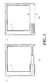
- the currently most used doors are automatic doors with horizontal sliding, also called sliding doors, which are usually formed as telescopic doors comprising a plurality of leaves, usually two leaves per door, which move in one and the same vertical plane, being opposed and stacked, at least partially overlapped, in parallel vertical planes when they are in the open position, as depicted in view B of Figure 1 , the closed position having been depicted in view A.
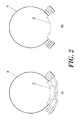
- Figure 2 shows a currently existing telescopic door comprising leaves with a cylindrical configuration, the closed position having been depicted in view A and the open position in view B.
- a second drawback is that the leaves of each door have one or several successive steps, which do not form a single plane, which is inconvenient for the users when occupying the inner space of the car, reduces the space available for the users, decreases the ergonomics thereof and affects the aesthetics of both the elevator and of the floors of the building.
- the safety regulations in force for the construction and installation of elevators UNE-EN 81-1 establishes maximum operative clearances between said small gaps or grooves of the leaves of the doors.
- EP-1449802-A1 describes an access system by means of telescopic doors, in which the number of leaves comprised in the car door is different from the number of leaves comprised by the floor door, all of this for the purpose of making flexible and optimizing the floor space of the elevator shaft occupied by the different components of the elevator, such as the car, the counterweight, the car door and the floor doors.
- JP-61005881-U and US-H1362 disclose doors for access of elevator apparatuses, namely, so-called “accordion” doors.
- These doors comprise leaves configured to move between a closed position, in which said leaves close an access of the elevator apparatus, and an open position, in which said access is at least partially open.
- the leaves In the closed position the leaves are opposed at their side edges, said side edges being flush with one another, whereas in the open position said leaves have pivoted with regards to adjacent leaves so that adjacent leaves are opposed and at least partially overlapped at their faces.
- a first aspect of the present invention relates to a door for accesses of elevator apparatuses, which allows increasing the efficiency of the space occupied by the elevator apparatus, specifically allowing increasing the surface of the floor of a car of the elevator apparatus which is freed up for being occupied, housing and transporting users and/or loads, likewise allowing improving the ergonomics and the safety conditions of said users.
- the door for accesses of elevator apparatuses proposed by the invention comprises at least two leaves which are configured to move between a closed position, in which said leaves close an access, either to a car or to a floor, of the elevator apparatus, and an open position, in which said access is at least partially open.
- the leaves are opposed at their side edges, said side edges being leveled, i.e., flush with one another, such that their faces are extended according to a straight line or a line of constant curvature, being at the same height or level and without there being a step between both leaves.
- said leaves are opposed and at least partially overlapped at their faces, without having to be in contact at said faces.
- the invention allows a decrease in the risk of a user experiencing injuries, especially in his or her fingers, given that the door lacks a step between leaves when it is in the closed position and during part of the trajectory of the leaves during the opening and the closing thereof.
- the door of the invention is extremely versatile, allowing its incorporation in any type of elevator apparatus, in addition to improving the aesthetics and ergonomics thereof due to the absence of a step between the leaves of the doors when they are in the closed position and during most of the movement of the leaves in the opening and closing operations, with the gain of space that this entails.
- the leaves are substantially planar surfaces and that in the closed position said leaves are substantially located in one and the same plane, i.e., they are coplanar, whereas in the open position said leaves are located in different planes. It is likewise contemplated that in the open position the leaves are located in at least two parallel planes.
- the leaves are substantially cylindrical surfaces and that in the closed position the leaves are substantially located in a cylindrical surface, whereas in the open position said leaves are located in different cylindrical surfaces, such that their horizontal edges are extended according to a line of constant curvature. It is likewise contemplated that in the open position said leaves are located in at least two substantially equidistant cylindrical surfaces.
- the leaves are configured to move without relative movement and being laterally connected to one another during a first section of the path between the closed and open positions, said leaves being configured to move with relative movement and being laterally disconnected from one another during a second section of said path.
- the leaves are configured to move with relative movement and being laterally connected to one another during an intermediate section located between the first and the second section of said path.
- the door of the invention comprises guiding means configured to guide the movement of the leaves indistinctly between the closed position and the open position, said guiding means comprising at least one rail comprising a straight section and a non-straight section.
- a second aspect of the invention relates to an elevator apparatus comprising at least one car comprising at least one car access, said at least one car being arranged to move through an elevator shaft comprising at least two floor accesses located at a different level, such that said elevator apparatus comprises at least one door such as the one described above.
- a third aspect of the invention relates to a method for operating a door such as the one described above, between a closed position, in which at least two leaves close an access of the elevator apparatus, and an open position, in which said access is at least partially open.
- the method comprises the following phases:
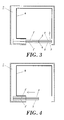
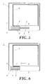
- the door for accesses of elevator apparatuses proposed by the invention comprises a car door comprising two leaves (1, 1') configured to move between a closed position, depicted in Figures 3 and 7 , in which the leaves (1, 1') close a car access (2) of the elevator apparatus, and an open position, depicted in Figures 6 and 8 , in which said car access (2) is open.
- the access of the elevator apparatus comprises a floor door comprising two leaves (1, 1') configured to move between a closed position, in which the leaves (1, 1') close a floor access (3) of the elevator apparatus, and an open position, in which said floor access (3) is open.
- Figures 3 to 6 show an embodiment of the door of the invention, in which the leaves (1, 1') are planar surfaces which in the closed position are located in one and the same plane, whereas in the open position said leaves (1, 1') are located in two parallel planes.
- Figures 7 and 8 show an embodiment variant of the door of the invention, in which the leaves (1, 1') are cylindrical surfaces which in the closed position are located in a cylindrical surface, whereas in the open position said leaves (1, 1') are located in two equidistant cylindrical surfaces, such that their horizontal edges are extended according to a line of constant curvature.
- the leaves (1, 1') of the doors can adopt any other configuration with a shape different from those described above, i.e., planar and cylindrical, within the object of the invention.
- the leaves (1, 1') of a door are configured to move without relative movement and being laterally connected to one another during a first section of the path between the close and open positions, said leaves (1, 1') being configured to move with relative movement and being laterally disconnected from one another during a second section of said path.
- the leaves (1, 1') are configured to move without relative movement and being laterally connected to one another during an intermediate section located between the first and second section of said path.
- the door comprises guiding means, not shown, configured to guide the movement of the leaves (1, 1') indistinctly between the closed position and the open position, said guiding means comprising at least one rail comprising a straight section and a non-straight section, such that the first section of the path of the leaves (1, 1') between the closed position and the open position is comprised in the straight section of the guiding means, whereas the intermediate section of said path corresponds to the non-linear section of said guiding means.
- the guiding means comprise at least one rail comprising at least two sections with different curvature.
- the guiding system comprises independent rails for each leaf of one and the same door, the trajectory of each leaf being determined by said rail. It is also contemplated that a part of a rail is common for at least two leaves.
- each door comprises a driving leaf (1) and a driven leaf (1') configured to be moved by the driving leaf (1) when they are connected, such that the car door is operated jointly in collaboration with the corresponding floor door by means of conventional couplings for elevator doors, said driven leaf (1') being a slave of the driving leaf (1) and being guided in folded profiles of the guiding system, such that upon reaching the end of its path towards the open position, the driven leaf (1') moves away from the trajectory of the driving leaf (1) and both leaves (1, 1') are stacked at their faces (5).
- connection between the leaves (1, 1') of a door is carried out by means of conventional attachment means available in the state of the art, not shown, configured to laterally connect said leaves (1, 1') to one another during said first section of the path and laterally disconnect said leaves (1, 1') from one another during the second section of the path.
- a leaf (1, 1') is joined to the other leaf (1, 1') by means of a mechanical mechanism which can consist of a rotating part serving to be able to guide and at the same time attach the driven leaf (1') with respect to the driving leaf (1) in a position whereas once rotated by an operation which releases and disconnects the driven leaf (1') once the first section of the path has ended.
- the attachment means can consist of electromechanical or electromagnetic elements, for example electromagnets which connect and disconnect the leaves (1, 1') controlled by a control unit.
- a second aspect of the invention relates to an elevator apparatus comprising a car (6) comprising a car access (2), said car (6) being arranged to move through an elevator shaft (7) comprising at least two floor accesses (3) located at a different level, such that said elevator apparatus comprises a door such as the one described above which is located in said car access (2) and floor accesses (3).
Landscapes
- Elevator Door Apparatuses (AREA)
Claims (15)
- Porte d'accès d'appareils élévateurs comprenant au moins deux vantaux (1, 1') configurés pour se déplacer entre une position fermée dans laquelle lesdits vantaux (1, 1') ferment un accès (2, 3) de l'appareil élévateur, et une position ouverte dans laquelle ledit accès (2, 3) est au moins partiellement ouvert,
dans laquelle :dans la position fermée, les vantaux (1, 1') sont opposés au niveau de leurs bords latéraux (4), lesdits bords latéraux (4) se situant au même niveau, alors que dans la position ouverte, lesdits vantaux (1, 1') sont opposés et au moins partiellement en chevauchement au niveau de leurs faces (5),et caractérisée en ce que :les vantaux (1, 1') sont configurés pour se déplacer sans mouvement relatif et sont latéralement raccordés l'un à l'autre pendant une première partie du trajet entre les positions fermée et ouverte, lesdits vantaux (1, 1') étant configurés pour se déplacer avec un mouvement relatif et étant latéralement déconnectés l'un de l'autre pendant une deuxième partie dudit trajet. - Porte d'accès d'appareils élévateurs comprenant au moins deux vantaux (1, 1') configurés pour se déplacer entre une position fermée dans laquelle lesdits vantaux (1, 1') ferment un accès (2, 3) de l'appareil élévateur, et une position ouverte dans laquelle ledit accès (2, 3) est au moins partiellement ouvert,
dans laquelle :dans la position fermée, les vantaux (1, 1') sont opposés au niveau de leurs bords latéraux (4), lesdits bords latéraux (4) se situant au même niveau, alors que dans la position ouverte, lesdits vantaux (1, 1') sont opposés et au moins partiellement en chevauchement au niveau de leurs faces (5),
et caractérisée en ce que :la porte comprend des moyens de guidage configurés pour guider le mouvement des vantaux (1, 1') indistinctement entre la position fermée et la position ouverte, lesdits moyens de guidage comprenant au moins un rail comprenant une section droite et une section qui n'est pas droite. - Porte d'accès d'appareils élévateurs selon la revendication 1 ou 2, dans laquelle les vantaux (1, 1') sont des surfaces sensiblement planes, et dans la position fermée lesdits vantaux (1, 1') sont sensiblement positionnés dans un seul et même plan, alors que dans la position ouverte lesdits vantaux (1, 1') sont positionnés dans des plans différents.
- Porte d'accès d'appareils élévateurs selon la revendication 3,
dans laquelle, dans la position ouverte, lesdits vantaux (1, 1') sont positionnés dans au moins deux plans parallèles. - Porte d'accès d'appareils élévateurs, comprenant au moins deux vantaux (1, 1') configurés pour se déplacer entre une position fermée dans laquelle lesdits vantaux (1, 1') ferment un accès (2, 3) de l'appareil élévateur, et une position ouverte dans laquelle ledit accès (2, 3) est au moins partiellement ouvert,
dans laquelle :dans la position fermée, les vantaux (1, 1') sont opposés au niveau de leurs bords latéraux (4), lesdits bords latéraux (4) se situant au même niveau, alors que dans la position ouverte, lesdits vantaux (1, 1') sont opposés et au moins partiellement en chevauchement au niveau de leurs faces (5),
et caractérisée en ce que :les vantaux (1, 1') sont des surfaces sensiblement cylindriques, et dans la position fermée les vantaux (1, 1') sont sensiblement positionnés dans une seule et même surface cylindrique, alors que dans la position ouverte lesdits vantaux (1, 1') sont positionnés dans des surfaces cylindriques différentes. - Porte d'accès d'appareils élévateurs selon la revendication 5, dans laquelle, dans la position ouverte, lesdits vantaux (1, 1') sont positionnés dans au moins deux surfaces cylindriques sensiblement équidistantes.
- Porte d'accès d'appareils élévateurs selon l'une quelconque des revendications 5 et 6, dans laquelle les vantaux (1, 1') sont configurés pour se déplacer sans mouvement relatif et sont latéralement raccordés l'un à l'autre pendant une première partie du trajet entre les positions fermée et ouverte, lesdits vantaux (1, 1') étant configurés pour se déplacer avec un mouvement relatif et étant latéralement déconnectés l'un de l'autre pendant une deuxième partie dudit trajet.
- Porte d'accès d'appareils élévateurs selon la revendication 1 ou 7, dans laquelle les vantaux (1, 1') sont configurés pour se déplacer avec un mouvement relatif et sont latéralement raccordés l'un à l'autre pendant une partie intermédiaire située entre les première et deuxième parties dudit trajet.
- Porte d'accès d'appareils élévateurs, comprenant au moins deux vantaux (1, 1') configurés pour se déplacer entre une position fermée dans laquelle lesdits vantaux (1, 1') ferment un accès (2, 3) de l'appareil élévateur, et une position ouverte dans laquelle ledit accès (2, 3) est au moins partiellement ouvert,
dans laquelle :dans la position fermée, les vantaux (1, 1') sont opposés au niveau de leurs bords latéraux (4), lesdits bords latéraux (4) se situant au même niveau, alors que dans la position ouverte, lesdits vantaux (1, 1') sont opposés et au moins partiellement en chevauchement au niveau de leurs faces (5),dans laquelle les vantaux sont des surfaces sensiblement planes,
et caractérisée en ce que :dans la position fermée les vantaux sont sensiblement positionnés dans un seul et même plan, alors que dans la position ouverte les vantaux sont positionnés dans au moins deux plans parallèles, lesdits deux plans parallèles étant parallèles audit premier plan. - Porte d'accès d'appareils élévateurs selon l'une quelconque des revendications précédentes, comprenant au moins un vantail d'entraînement (1) et au moins un vantail entraîné (1') configuré pour être déplacé par ledit au moins un vantail d'entraînement (1) lorsqu'ils sont raccordés.
- Porte d'accès d'appareils élévateurs selon l'une quelconque des revendications 1, 7 et 8, dans laquelle le raccordement entre lesdits au moins deux vantaux (1, 1') est réalisé au moyen de moyens de fixation configurés pour raccorder latéralement lesdits vantaux (1, 1') l'un à l'autre pendant ladite première partie du trajet et déconnecter latéralement lesdits vantaux (1, 1') l'un de l'autre pendant la deuxième partie du trajet.
- Appareil élévateur comprenant au moins une cabine (6) comprenant au moins un accès de cabine (2), ladite au moins une cabine (6) étant agencée pour se déplacer à travers une cage élévatrice (7) comprenant au moins deux accès d'étage (3) positionnés à un niveau différent, ledit appareil élévateur comprenant au moins une porte selon l'une quelconque des revendications 1 à 11.
- Appareil élévateur selon la revendication 12, dans lequel au moins une porte est positionnée dans ledit au moins un accès de cabine (2).
- Appareil élévateur selon l'une quelconque des revendications 12 et 13, dans lequel au moins une porte est positionnée dans un accès d'étage (3).
- Procédé pour actionner une porte selon l'une quelconque des revendications 1 à 11, entre une position fermée dans laquelle au moins deux vantaux (1, 1') ferment un accès (2, 3) de l'appareil élévateur, et une position ouverte dans laquelle ledit accès (2, 3) est au moins partiellement ouvert, caractérisé en ce que le procédé comprend les étapes suivantes :une première étape dans laquelle lesdits au moins deux vantaux (1, 1') se déplacent sans mouvement relatif et sont latéralement raccordés l'un à l'autre ; etune deuxième étape dans laquelle lesdits au moins deux vantaux (1, 1') se déplacent avec un mouvement relatif et sont latéralement déconnectés l'un de l'autre.
Applications Claiming Priority (1)
| Application Number | Priority Date | Filing Date | Title |
|---|---|---|---|
| ES200803632A ES2356975B1 (es) | 2008-12-19 | 2008-12-19 | Puerta para acceso de aparatos elevadores, aparato elevador y método para accionar dicha puerta. |
Publications (2)
| Publication Number | Publication Date |
|---|---|
| EP2199246A1 EP2199246A1 (fr) | 2010-06-23 |
| EP2199246B1 true EP2199246B1 (fr) | 2012-04-25 |
Family
ID=41809218
Family Applications (1)
| Application Number | Title | Priority Date | Filing Date |
|---|---|---|---|
| EP09382289A Not-in-force EP2199246B1 (fr) | 2008-12-19 | 2009-12-21 | Porte d'accès d'appareils élévateurs, appareil élévateur et procédé de fonctionnement de ladite porte |
Country Status (4)
| Country | Link |
|---|---|
| EP (1) | EP2199246B1 (fr) |
| AT (1) | ATE555050T1 (fr) |
| ES (2) | ES2356975B1 (fr) |
| PT (1) | PT2199246E (fr) |
Families Citing this family (1)
| Publication number | Priority date | Publication date | Assignee | Title |
|---|---|---|---|---|
| EP3800157B1 (fr) * | 2019-10-04 | 2023-02-15 | Otis Elevator Company | Tablier d'ascenseur |
Family Cites Families (9)
| Publication number | Priority date | Publication date | Assignee | Title |
|---|---|---|---|---|
| FR955968A (fr) * | 1950-01-23 | |||
| US2175323A (en) * | 1937-03-03 | 1939-10-10 | Oscar F Shepard | Elevator closure |
| JPS615881U (ja) * | 1984-06-15 | 1986-01-14 | 株式会社日立製作所 | エレベ−タ−用折り戸装置 |
| GB2194578A (en) * | 1986-08-15 | 1988-03-09 | Reytrac Ltd | Sliding door |
| JPS63171590U (fr) * | 1987-04-28 | 1988-11-08 | ||
| USH1362H (en) * | 1993-03-08 | 1994-10-04 | Herrmann; Walter J. | Drive mechanism for elevator door |
| EP1449802B1 (fr) | 2003-02-24 | 2007-10-24 | Inventio Ag | Portes d'ascenseur combinées |
| ITPR20030039A1 (it) | 2003-05-23 | 2004-11-24 | Wittur Spa | Porta cabina e porta di piano per ascensori e/o elevatori. |
| ES2255799B1 (es) * | 2004-02-09 | 2007-03-01 | Salvador Estrada Monte | Puerta articulada. |
-
2008
- 2008-12-19 ES ES200803632A patent/ES2356975B1/es not_active Expired - Fee Related
-
2009
- 2009-12-21 PT PT09382289T patent/PT2199246E/pt unknown
- 2009-12-21 EP EP09382289A patent/EP2199246B1/fr not_active Not-in-force
- 2009-12-21 AT AT09382289T patent/ATE555050T1/de active
- 2009-12-21 ES ES09382289T patent/ES2384205T3/es active Active
Also Published As
| Publication number | Publication date |
|---|---|
| ES2356975A1 (es) | 2011-04-15 |
| ATE555050T1 (de) | 2012-05-15 |
| PT2199246E (pt) | 2012-06-18 |
| EP2199246A1 (fr) | 2010-06-23 |
| ES2384205T3 (es) | 2012-07-02 |
| ES2356975B1 (es) | 2012-02-13 |
Similar Documents
| Publication | Publication Date | Title |
|---|---|---|
| EP2229335B1 (fr) | Circuit pour réinitialiser une chaîne de sécurité d'ascenseur | |
| EP2558393B1 (fr) | Butée rétractable pour des ascenseurs à plafond bas | |
| CN103562116B (zh) | 电梯门装置及电梯设备 | |
| EP2782861B1 (fr) | Ascenseur | |
| EP3187452B1 (fr) | Ensemble coupleur de porte d'ascenseur | |
| JP6030209B1 (ja) | エレベータ装置 | |
| EP3342739A1 (fr) | Module de commutation de fosse de porte palière d'ascenseur | |
| JP5448306B2 (ja) | エレベータのかご側ドア施錠装置 | |
| JP6272507B2 (ja) | エレベータ装置 | |
| EP1343712B1 (fr) | Dispositif de securite pour ascenseur | |
| EP2199246A1 (fr) | Porte d'accès d'appareils élévateurs, appareil élévateur et procédé de fonctionnement de ladite porte | |
| JP6068602B1 (ja) | エレベータ装置 | |
| WO2016103318A1 (fr) | Dispositif d'ascenseur | |
| CN107835781B (zh) | 电梯装置 | |
| JP6058710B2 (ja) | エレベータ装置 | |
| JP5981628B1 (ja) | エレベータ装置 | |
| CN208916567U (zh) | 具有伸缩功能的悬挂式轨道的升降机滑门结构 | |
| JP6271652B2 (ja) | エレベータ装置 | |
| JP2007326684A (ja) | エレベータ装置 | |
| US20080011556A1 (en) | Elevator door operator and interlock arrangement | |
| WO2011159300A1 (fr) | Ensemble porte d'ascenseur comprenant une couche de coulisseau en matériau à frottement réduit | |
| KR20100093841A (ko) | 엘리베이터의 보조 안전도어 개폐장치 | |
| WO2026087998A1 (fr) | Système d'ascenseur pour un bâtiment | |
| HK1236021A1 (en) | Elevator apparatus | |
| HK1179593B (en) | Retractable stop for low overhead elevators |
Legal Events
| Date | Code | Title | Description |
|---|---|---|---|
| PUAI | Public reference made under article 153(3) epc to a published international application that has entered the european phase |
Free format text: ORIGINAL CODE: 0009012 |
|
| AK | Designated contracting states |
Kind code of ref document: A1 Designated state(s): AT BE BG CH CY CZ DE DK EE ES FI FR GB GR HR HU IE IS IT LI LT LU LV MC MK MT NL NO PL PT RO SE SI SK SM TR |
|
| AX | Request for extension of the european patent |
Extension state: AL BA RS |
|
| 17P | Request for examination filed |
Effective date: 20100816 |
|
| RIC1 | Information provided on ipc code assigned before grant |
Ipc: B66B 13/08 20060101AFI20110921BHEP |
|
| GRAP | Despatch of communication of intention to grant a patent |
Free format text: ORIGINAL CODE: EPIDOSNIGR1 |
|
| GRAS | Grant fee paid |
Free format text: ORIGINAL CODE: EPIDOSNIGR3 |
|
| GRAA | (expected) grant |
Free format text: ORIGINAL CODE: 0009210 |
|
| AK | Designated contracting states |
Kind code of ref document: B1 Designated state(s): AT BE BG CH CY CZ DE DK EE ES FI FR GB GR HR HU IE IS IT LI LT LU LV MC MK MT NL NO PL PT RO SE SI SK SM TR |
|
| REG | Reference to a national code |
Ref country code: GB Ref legal event code: FG4D |
|
| REG | Reference to a national code |
Ref country code: CH Ref legal event code: EP |
|
| REG | Reference to a national code |
Ref country code: AT Ref legal event code: REF Ref document number: 555050 Country of ref document: AT Kind code of ref document: T Effective date: 20120515 |
|
| REG | Reference to a national code |
Ref country code: IE Ref legal event code: FG4D |
|
| REG | Reference to a national code |
Ref country code: PT Ref legal event code: SC4A Free format text: AVAILABILITY OF NATIONAL TRANSLATION Effective date: 20120605 |
|
| REG | Reference to a national code |
Ref country code: DE Ref legal event code: R096 Ref document number: 602009006525 Country of ref document: DE Effective date: 20120628 |
|
| REG | Reference to a national code |
Ref country code: ES Ref legal event code: FG2A Ref document number: 2384205 Country of ref document: ES Kind code of ref document: T3 Effective date: 20120702 |
|
| REG | Reference to a national code |
Ref country code: NL Ref legal event code: VDEP Effective date: 20120425 |
|
| REG | Reference to a national code |
Ref country code: AT Ref legal event code: MK05 Ref document number: 555050 Country of ref document: AT Kind code of ref document: T Effective date: 20120425 |
|
| LTIE | Lt: invalidation of european patent or patent extension |
Effective date: 20120425 |
|
| PG25 | Lapsed in a contracting state [announced via postgrant information from national office to epo] |
Ref country code: SE Free format text: LAPSE BECAUSE OF FAILURE TO SUBMIT A TRANSLATION OF THE DESCRIPTION OR TO PAY THE FEE WITHIN THE PRESCRIBED TIME-LIMIT Effective date: 20120425 Ref country code: CY Free format text: LAPSE BECAUSE OF FAILURE TO SUBMIT A TRANSLATION OF THE DESCRIPTION OR TO PAY THE FEE WITHIN THE PRESCRIBED TIME-LIMIT Effective date: 20120425 Ref country code: IS Free format text: LAPSE BECAUSE OF FAILURE TO SUBMIT A TRANSLATION OF THE DESCRIPTION OR TO PAY THE FEE WITHIN THE PRESCRIBED TIME-LIMIT Effective date: 20120825 Ref country code: PL Free format text: LAPSE BECAUSE OF FAILURE TO SUBMIT A TRANSLATION OF THE DESCRIPTION OR TO PAY THE FEE WITHIN THE PRESCRIBED TIME-LIMIT Effective date: 20120425 Ref country code: FI Free format text: LAPSE BECAUSE OF FAILURE TO SUBMIT A TRANSLATION OF THE DESCRIPTION OR TO PAY THE FEE WITHIN THE PRESCRIBED TIME-LIMIT Effective date: 20120425 Ref country code: NO Free format text: LAPSE BECAUSE OF FAILURE TO SUBMIT A TRANSLATION OF THE DESCRIPTION OR TO PAY THE FEE WITHIN THE PRESCRIBED TIME-LIMIT Effective date: 20120725 Ref country code: LT Free format text: LAPSE BECAUSE OF FAILURE TO SUBMIT A TRANSLATION OF THE DESCRIPTION OR TO PAY THE FEE WITHIN THE PRESCRIBED TIME-LIMIT Effective date: 20120425 |
|
| PG25 | Lapsed in a contracting state [announced via postgrant information from national office to epo] |
Ref country code: LV Free format text: LAPSE BECAUSE OF FAILURE TO SUBMIT A TRANSLATION OF THE DESCRIPTION OR TO PAY THE FEE WITHIN THE PRESCRIBED TIME-LIMIT Effective date: 20120425 Ref country code: SI Free format text: LAPSE BECAUSE OF FAILURE TO SUBMIT A TRANSLATION OF THE DESCRIPTION OR TO PAY THE FEE WITHIN THE PRESCRIBED TIME-LIMIT Effective date: 20120425 Ref country code: HR Free format text: LAPSE BECAUSE OF FAILURE TO SUBMIT A TRANSLATION OF THE DESCRIPTION OR TO PAY THE FEE WITHIN THE PRESCRIBED TIME-LIMIT Effective date: 20120425 Ref country code: GR Free format text: LAPSE BECAUSE OF FAILURE TO SUBMIT A TRANSLATION OF THE DESCRIPTION OR TO PAY THE FEE WITHIN THE PRESCRIBED TIME-LIMIT Effective date: 20120726 |
|
| PG25 | Lapsed in a contracting state [announced via postgrant information from national office to epo] |
Ref country code: BE Free format text: LAPSE BECAUSE OF FAILURE TO SUBMIT A TRANSLATION OF THE DESCRIPTION OR TO PAY THE FEE WITHIN THE PRESCRIBED TIME-LIMIT Effective date: 20120425 |
|
| PG25 | Lapsed in a contracting state [announced via postgrant information from national office to epo] |
Ref country code: CZ Free format text: LAPSE BECAUSE OF FAILURE TO SUBMIT A TRANSLATION OF THE DESCRIPTION OR TO PAY THE FEE WITHIN THE PRESCRIBED TIME-LIMIT Effective date: 20120425 Ref country code: EE Free format text: LAPSE BECAUSE OF FAILURE TO SUBMIT A TRANSLATION OF THE DESCRIPTION OR TO PAY THE FEE WITHIN THE PRESCRIBED TIME-LIMIT Effective date: 20120425 Ref country code: DK Free format text: LAPSE BECAUSE OF FAILURE TO SUBMIT A TRANSLATION OF THE DESCRIPTION OR TO PAY THE FEE WITHIN THE PRESCRIBED TIME-LIMIT Effective date: 20120425 Ref country code: SK Free format text: LAPSE BECAUSE OF FAILURE TO SUBMIT A TRANSLATION OF THE DESCRIPTION OR TO PAY THE FEE WITHIN THE PRESCRIBED TIME-LIMIT Effective date: 20120425 Ref country code: AT Free format text: LAPSE BECAUSE OF FAILURE TO SUBMIT A TRANSLATION OF THE DESCRIPTION OR TO PAY THE FEE WITHIN THE PRESCRIBED TIME-LIMIT Effective date: 20120425 Ref country code: RO Free format text: LAPSE BECAUSE OF FAILURE TO SUBMIT A TRANSLATION OF THE DESCRIPTION OR TO PAY THE FEE WITHIN THE PRESCRIBED TIME-LIMIT Effective date: 20120425 Ref country code: NL Free format text: LAPSE BECAUSE OF FAILURE TO SUBMIT A TRANSLATION OF THE DESCRIPTION OR TO PAY THE FEE WITHIN THE PRESCRIBED TIME-LIMIT Effective date: 20120425 |
|
| PLBE | No opposition filed within time limit |
Free format text: ORIGINAL CODE: 0009261 |
|
| STAA | Information on the status of an ep patent application or granted ep patent |
Free format text: STATUS: NO OPPOSITION FILED WITHIN TIME LIMIT |
|
| 26N | No opposition filed |
Effective date: 20130128 |
|
| REG | Reference to a national code |
Ref country code: DE Ref legal event code: R097 Ref document number: 602009006525 Country of ref document: DE Effective date: 20130128 |
|
| PG25 | Lapsed in a contracting state [announced via postgrant information from national office to epo] |
Ref country code: MC Free format text: LAPSE BECAUSE OF NON-PAYMENT OF DUE FEES Effective date: 20121231 Ref country code: BG Free format text: LAPSE BECAUSE OF FAILURE TO SUBMIT A TRANSLATION OF THE DESCRIPTION OR TO PAY THE FEE WITHIN THE PRESCRIBED TIME-LIMIT Effective date: 20120725 |
|
| PG25 | Lapsed in a contracting state [announced via postgrant information from national office to epo] |
Ref country code: MT Free format text: LAPSE BECAUSE OF FAILURE TO SUBMIT A TRANSLATION OF THE DESCRIPTION OR TO PAY THE FEE WITHIN THE PRESCRIBED TIME-LIMIT Effective date: 20120425 |
|
| PG25 | Lapsed in a contracting state [announced via postgrant information from national office to epo] |
Ref country code: TR Free format text: LAPSE BECAUSE OF FAILURE TO SUBMIT A TRANSLATION OF THE DESCRIPTION OR TO PAY THE FEE WITHIN THE PRESCRIBED TIME-LIMIT Effective date: 20120425 |
|
| PG25 | Lapsed in a contracting state [announced via postgrant information from national office to epo] |
Ref country code: SM Free format text: LAPSE BECAUSE OF FAILURE TO SUBMIT A TRANSLATION OF THE DESCRIPTION OR TO PAY THE FEE WITHIN THE PRESCRIBED TIME-LIMIT Effective date: 20120425 Ref country code: LU Free format text: LAPSE BECAUSE OF NON-PAYMENT OF DUE FEES Effective date: 20121221 |
|
| PG25 | Lapsed in a contracting state [announced via postgrant information from national office to epo] |
Ref country code: HU Free format text: LAPSE BECAUSE OF FAILURE TO SUBMIT A TRANSLATION OF THE DESCRIPTION OR TO PAY THE FEE WITHIN THE PRESCRIBED TIME-LIMIT Effective date: 20091221 |
|
| REG | Reference to a national code |
Ref country code: CH Ref legal event code: PL |
|
| PG25 | Lapsed in a contracting state [announced via postgrant information from national office to epo] |
Ref country code: CH Free format text: LAPSE BECAUSE OF NON-PAYMENT OF DUE FEES Effective date: 20131231 Ref country code: LI Free format text: LAPSE BECAUSE OF NON-PAYMENT OF DUE FEES Effective date: 20131231 |
|
| PG25 | Lapsed in a contracting state [announced via postgrant information from national office to epo] |
Ref country code: MK Free format text: LAPSE BECAUSE OF FAILURE TO SUBMIT A TRANSLATION OF THE DESCRIPTION OR TO PAY THE FEE WITHIN THE PRESCRIBED TIME-LIMIT Effective date: 20120425 |
|
| REG | Reference to a national code |
Ref country code: FR Ref legal event code: PLFP Year of fee payment: 7 |
|
| REG | Reference to a national code |
Ref country code: FR Ref legal event code: PLFP Year of fee payment: 8 |
|
| REG | Reference to a national code |
Ref country code: FR Ref legal event code: PLFP Year of fee payment: 9 |
|
| PGFP | Annual fee paid to national office [announced via postgrant information from national office to epo] |
Ref country code: DE Payment date: 20181211 Year of fee payment: 10 Ref country code: IE Payment date: 20181220 Year of fee payment: 10 Ref country code: PT Payment date: 20181217 Year of fee payment: 10 |
|
| PGFP | Annual fee paid to national office [announced via postgrant information from national office to epo] |
Ref country code: IT Payment date: 20181203 Year of fee payment: 10 Ref country code: GB Payment date: 20181218 Year of fee payment: 10 Ref country code: FR Payment date: 20181220 Year of fee payment: 10 |
|
| PGFP | Annual fee paid to national office [announced via postgrant information from national office to epo] |
Ref country code: ES Payment date: 20200114 Year of fee payment: 11 |
|
| REG | Reference to a national code |
Ref country code: DE Ref legal event code: R119 Ref document number: 602009006525 Country of ref document: DE |
|
| GBPC | Gb: european patent ceased through non-payment of renewal fee |
Effective date: 20191221 |
|
| PG25 | Lapsed in a contracting state [announced via postgrant information from national office to epo] |
Ref country code: FR Free format text: LAPSE BECAUSE OF NON-PAYMENT OF DUE FEES Effective date: 20191231 Ref country code: GB Free format text: LAPSE BECAUSE OF NON-PAYMENT OF DUE FEES Effective date: 20191221 Ref country code: PT Free format text: LAPSE BECAUSE OF NON-PAYMENT OF DUE FEES Effective date: 20200723 Ref country code: IE Free format text: LAPSE BECAUSE OF NON-PAYMENT OF DUE FEES Effective date: 20191221 Ref country code: DE Free format text: LAPSE BECAUSE OF NON-PAYMENT OF DUE FEES Effective date: 20200701 Ref country code: IT Free format text: LAPSE BECAUSE OF NON-PAYMENT OF DUE FEES Effective date: 20191221 |
|
| REG | Reference to a national code |
Ref country code: ES Ref legal event code: FD2A Effective date: 20220222 |
|
| PG25 | Lapsed in a contracting state [announced via postgrant information from national office to epo] |
Ref country code: ES Free format text: LAPSE BECAUSE OF NON-PAYMENT OF DUE FEES Effective date: 20201222 |