EP2199532A2 - Outil de forage pour des roches - Google Patents
Outil de forage pour des roches Download PDFInfo
- Publication number
- EP2199532A2 EP2199532A2 EP09176741A EP09176741A EP2199532A2 EP 2199532 A2 EP2199532 A2 EP 2199532A2 EP 09176741 A EP09176741 A EP 09176741A EP 09176741 A EP09176741 A EP 09176741A EP 2199532 A2 EP2199532 A2 EP 2199532A2
- Authority
- EP
- European Patent Office
- Prior art keywords
- drilling tool
- rotary driving
- drill head
- tool according
- locking means
- Prior art date
- Legal status (The legal status is an assumption and is not a legal conclusion. Google has not performed a legal analysis and makes no representation as to the accuracy of the status listed.)
- Withdrawn
Links
- 238000005553 drilling Methods 0.000 title claims description 26
- 239000004575 stone Substances 0.000 title 1
- 230000008878 coupling Effects 0.000 claims abstract description 9
- 238000010168 coupling process Methods 0.000 claims abstract description 9
- 238000005859 coupling reaction Methods 0.000 claims abstract description 9
- 239000011435 rock Substances 0.000 claims description 4
- 230000037431 insertion Effects 0.000 description 3
- 238000003780 insertion Methods 0.000 description 3
- 238000004519 manufacturing process Methods 0.000 description 3
- 238000011010 flushing procedure Methods 0.000 description 2
- 238000005516 engineering process Methods 0.000 description 1
- 239000000463 material Substances 0.000 description 1
- 239000002184 metal Substances 0.000 description 1
- 230000002093 peripheral effect Effects 0.000 description 1
Images

Classifications
-
- E—FIXED CONSTRUCTIONS
- E21—EARTH OR ROCK DRILLING; MINING
- E21B—EARTH OR ROCK DRILLING; OBTAINING OIL, GAS, WATER, SOLUBLE OR MELTABLE MATERIALS OR A SLURRY OF MINERALS FROM WELLS
- E21B17/00—Drilling rods or pipes; Flexible drill strings; Kellies; Drill collars; Sucker rods; Cables; Casings; Tubings
- E21B17/02—Couplings; joints
- E21B17/04—Couplings; joints between rod or the like and bit or between rod and rod or the like
- E21B17/046—Couplings; joints between rod or the like and bit or between rod and rod or the like with ribs, pins, or jaws, and complementary grooves or the like, e.g. bayonet catches
-
- B—PERFORMING OPERATIONS; TRANSPORTING
- B23—MACHINE TOOLS; METAL-WORKING NOT OTHERWISE PROVIDED FOR
- B23B—TURNING; BORING
- B23B51/00—Tools for drilling machines
-
- B—PERFORMING OPERATIONS; TRANSPORTING
- B28—WORKING CEMENT, CLAY, OR STONE
- B28D—WORKING STONE OR STONE-LIKE MATERIALS
- B28D1/00—Working stone or stone-like materials, e.g. brick, concrete or glass, not provided for elsewhere; Machines, devices, tools therefor
- B28D1/14—Working stone or stone-like materials, e.g. brick, concrete or glass, not provided for elsewhere; Machines, devices, tools therefor by boring or drilling
- B28D1/146—Tools therefor
-
- E—FIXED CONSTRUCTIONS
- E21—EARTH OR ROCK DRILLING; MINING
- E21B—EARTH OR ROCK DRILLING; OBTAINING OIL, GAS, WATER, SOLUBLE OR MELTABLE MATERIALS OR A SLURRY OF MINERALS FROM WELLS
- E21B19/00—Handling rods, casings, tubes or the like outside the borehole, e.g. in the derrick; Apparatus for feeding the rods or cables
- E21B19/18—Connecting or disconnecting drill bit and drilling pipe
-
- B—PERFORMING OPERATIONS; TRANSPORTING
- B23—MACHINE TOOLS; METAL-WORKING NOT OTHERWISE PROVIDED FOR
- B23B—TURNING; BORING
- B23B2226/00—Materials of tools or workpieces not comprising a metal
- B23B2226/75—Stone, rock or concrete
-
- B—PERFORMING OPERATIONS; TRANSPORTING
- B23—MACHINE TOOLS; METAL-WORKING NOT OTHERWISE PROVIDED FOR
- B23B—TURNING; BORING
- B23B2251/00—Details of tools for drilling machines
- B23B2251/02—Connections between shanks and removable cutting heads
Definitions
- the present invention relates to a drilling tool for rock referred to in the preamble of claim 1. Art.
- Such drilling tools for rock have an at least partially hollow boring bar with a flushing channel, a drive-side insertion for receiving in the tool holder of a driving Bohrtechniks and a driven-side coupling means and a rotationally fixed thereto and releasably connected by means of a locking means drill head with flushing openings and cutting hard material.
- a drilling tool for rock with an at least partially rotating and hitting claimed drill rod and a carbide occupied with hard drill head The drill rod and the drill head are rotatably limited by a coupling means axially movable and detachably connected to one another via a locking means, wherein at least one radially projecting rotational support web is arranged at one end face of the drill rod.
- the rotary driving web engages in at least one along the tool axis extending rotational drive slot of a rotary drive surface of a cup-shaped drill head.
- Object of the present invention is to further improve the known drilling tool and in particular to simplify the assembly and disassembly of drill head to the drill rod.
- the coupling means has elastic locking means for holding the rotary driving land in the rotary driving slot.
- the elastic locking means are arranged on the boring bar, whereby additional costs in the production of the drill heads are avoided and any additional costs for the boring bar due to the longer service life of the boring bar only slightly affect the overall cost.
- the elastic locking means may also be arranged on the drill head, whereby the noise emission of the drilling tool is reduced.
- this variant is particularly advantageous for smaller drill diameters.
- the elastic locking means comprise a spring element disposed on the rotary driving web, which is resiliently movable in a circumferential direction of the boring bar.
- the elastic locking means comprise a spring element arranged on the drill head which is resiliently movable in a circumferential direction of the drill head.
- the elastic locking means comprise at least one elastic wall portion of the drill head.
- the width of the rotary driving slot in the region of the opening is smaller than the largest width of the rotary driving web.
- the elastic deformability of the drill head or its peripheral wall is advantageously utilized.
- a narrowing of the rotary driving slot is achieved in that a projection which tapers the opening is arranged on the wall section in the region of the axial opening of the rotary driving slot.
- a further slot is arranged in the wall section in a region lying behind the projection in a working direction of rotation. As a result, the elastic expansion of the opening or the narrowed point during insertion and withdrawal of the rotary driving web is facilitated from the rotary driving slot.
- the rotary driving slot in the region of its opening at least one chamfer, whereby the widening of the opening or the bottleneck of the rotary driving slot is facilitated by the rotary driving web.
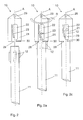
- FIGS. 1a to 1c is a first inventive drilling tool 10, which extends along a tool axis A reproduced.
- This drilling tool 10 has a drill head 21, which carries a cutting body 29 made of hard metal, and an elongated boring bar 11.
- the drill head 21 and the boring bar 11 are provided with coupling means which have four rotational engagement slots 22 running along the tool axis A at the drill head 21 and four rotational support webs 12 arranged at a front end of the drill rod 11.
- a course of the rotational engagement slots 22 at an angle of up to 25 ° relative to the tool axis A is also understood as extending along or along a tool axis.
- the Drehit Vietnamesestege 12 can be inserted via axial openings 28 of the rotary drive slots 22 in each case in the associated rotational drive slots 22 to releasably but rotatably set the drill head 21 on the drill rod 11.
- the openings 28 have as Einöffleicht ceremonies for the rotary driving webs 12 each at least one side of the openings 28 a chamfer 27.
- the rotary driving webs 12 are preferably tapered at its end facing the drill head 21 in order to facilitate insertion into the rotary driving slots.
- rotational engagement slots 22 each have a locking lug 30 in the rotational drive slots 22 and prevented in the manner of a bayonet locking an extension of the rotary driving webs 12 during the drilling operation.
- At least one of the rotary driving webs 21 is on the side opposite to the direction of rotation R, still designed as a spring bridge spring element 13 is arranged, which acts as an elastic locking means and on the drill head 21 when he as out Fig. 1c can be seen attached to the drill rod 21, against the working direction of rotation R is acted upon elastically.
- the Drehit Cyprusstege 12 are thereby held in the on the locking lugs 30 partially axially closed areas of the rotary drive slots 22.
- the spring element 13 is at least limited resiliently movable in a circumferential direction of the drill rod 11.
- the drill head 21 is held securely and captively on the drill rod 11 via the coupling means in combination with the elastic locking means.
- FIGS. 2a to 2c shown drilling tool 10 differs from that in the FIGS. 1a to 1c illustrated drilling tool, that instead of the spring element 13 on the rotary driving web 21 there is arranged a spring element 23 designed as a spring tongue elastic locking means in at least one of the rotary drive slots 12 which is resiliently movable in a circumferential direction of the drill head 21.
- the function of the spring element 23 corresponds to the previous to the FIGS. 1a to 1c For this reason, and because of reference numerals not mentioned here, reference is made in its entirety to the description of FIGS FIGS. 1a to 1 c.
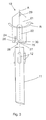
- FIG. 3 shown drilling tool 10 differs from that in the FIGS. 1a to 1c illustrated drilling tool that the elastic locking means there instead of the spring element 13 on the rotary driving web 21 at least one elastic wall portion 24 of the drill head 21 and at least one projecting from the wall portion 24 and the rotational driving slot 22 in the region of its axial opening 28 tapered projection 25 include. Further, in addition to the wall portion 24 in a working direction of rotation R behind the projection 25 area another slot 26 is arranged, which increases the elastic mobility of the wall portion 24.
- the projection 25 in this case has the chamfer 27 in the form of a curved outer contour, which facilitates the widening of the opening 28 of the rotary driving slot 22 by the rotary driving web 12.
- the function of the elastic wall section 24 corresponds to the function of the previous to the FIGS. 1a to 2c described spring elements 13, 23, why reference is made in this respect and because not mentioned here reference numerals to the description of the FIGS. 1a to 2c ,
Landscapes
- Engineering & Computer Science (AREA)
- Mining & Mineral Resources (AREA)
- Geology (AREA)
- Life Sciences & Earth Sciences (AREA)
- Mechanical Engineering (AREA)
- Environmental & Geological Engineering (AREA)
- Fluid Mechanics (AREA)
- Physics & Mathematics (AREA)
- General Life Sciences & Earth Sciences (AREA)
- Geochemistry & Mineralogy (AREA)
- Processing Of Stones Or Stones Resemblance Materials (AREA)
- Drilling Tools (AREA)
- Percussive Tools And Related Accessories (AREA)
- Earth Drilling (AREA)
Applications Claiming Priority (1)
| Application Number | Priority Date | Filing Date | Title |
|---|---|---|---|
| DE102008054925A DE102008054925B4 (de) | 2008-12-18 | 2008-12-18 | Bohrwerkzeug für Gestein |
Publications (2)
| Publication Number | Publication Date |
|---|---|
| EP2199532A2 true EP2199532A2 (fr) | 2010-06-23 |
| EP2199532A3 EP2199532A3 (fr) | 2016-03-09 |
Family
ID=42027888
Family Applications (1)
| Application Number | Title | Priority Date | Filing Date |
|---|---|---|---|
| EP09176741.8A Withdrawn EP2199532A3 (fr) | 2008-12-18 | 2009-11-23 | Outil de forage pour des roches |
Country Status (5)
| Country | Link |
|---|---|
| US (1) | US20100155144A1 (fr) |
| EP (1) | EP2199532A3 (fr) |
| JP (1) | JP2010142946A (fr) |
| CN (1) | CN101745988A (fr) |
| DE (1) | DE102008054925B4 (fr) |
Families Citing this family (7)
| Publication number | Priority date | Publication date | Assignee | Title |
|---|---|---|---|---|
| US9028180B2 (en) | 2012-04-04 | 2015-05-12 | Iscar, Ltd. | Cutting tool and cutting head with a resilient coupling portion |
| JP5983084B2 (ja) * | 2012-06-24 | 2016-08-31 | 日立工機株式会社 | 釘打機 |
| US8882413B2 (en) | 2012-11-26 | 2014-11-11 | Iscar, Ltd. | Cutting tool and cutting insert with a rearward resilience slit |
| CN106555554B (zh) * | 2016-11-24 | 2018-07-03 | 宜昌市燕狮科技开发有限责任公司 | 一种带卷簧的插销式钻杆接套 |
| CN111894565B (zh) * | 2020-07-14 | 2024-03-22 | 中煤科工开采研究院有限公司 | 用于测试围岩中裂缝扩展的装置 |
| JP2023107577A (ja) * | 2022-01-24 | 2023-08-03 | 株式会社大林組 | 穿孔装置、着脱方法及びコアビット |
| CN117868928B (zh) * | 2024-01-03 | 2026-05-15 | 神华神东电力有限责任公司 | 钻杆结构和钻机 |
Citations (1)
| Publication number | Priority date | Publication date | Assignee | Title |
|---|---|---|---|---|
| EP1267033A1 (fr) | 2001-06-15 | 2002-12-18 | HILTI Aktiengesellschaft | Outil de forage pour roche |
Family Cites Families (11)
| Publication number | Priority date | Publication date | Assignee | Title |
|---|---|---|---|---|
| US611305A (en) * | 1898-09-27 | Pipe-lock | ||
| US1526565A (en) * | 1923-06-16 | 1925-02-17 | William C Siderfin | Mining bit |
| GB690531A (en) * | 1950-06-28 | 1953-04-22 | Sandvikens Jernverks Ab | Drill rod assembly for rock drilling operations |
| US3575446A (en) * | 1969-02-28 | 1971-04-20 | Don W Brantley | Quick-connect coupler |
| DE3533929A1 (de) * | 1985-05-07 | 1986-11-13 | Geißler & Kuper GmbH Diamantwerkzeug - Wiederaufbereitung, 3100 Celle | Diamantbohrkrone mit schaftrohr und rohrgewindeanschluss |
| FR2694053B1 (fr) * | 1992-07-24 | 1994-09-02 | Souriau & Cie | Ensemble de connexion à verrouillage du type baïonnette. |
| AU3160395A (en) * | 1994-08-01 | 1996-03-04 | Stanislav Fiala | Finishing tool for precision machining of holes |
| US5741084A (en) * | 1995-03-27 | 1998-04-21 | Del Rio; Eddy H. | Wear compensating axial connection |
| GB2324486B (en) * | 1997-04-24 | 2001-06-20 | Marcrist Ind Ltd | Masonry core-cutting tool |
| EP0909870A1 (fr) * | 1997-10-15 | 1999-04-21 | DIAMANT BOART Société Anonyme | Accouplement pour dispositif à transmission de forces |
| DE20119532U1 (de) * | 2001-12-01 | 2002-02-28 | Englert, Thomas, 63762 Großostheim | Kupplung |
-
2008
- 2008-12-18 DE DE102008054925A patent/DE102008054925B4/de not_active Expired - Fee Related
-
2009
- 2009-11-23 EP EP09176741.8A patent/EP2199532A3/fr not_active Withdrawn
- 2009-12-15 JP JP2009284388A patent/JP2010142946A/ja active Pending
- 2009-12-17 US US12/640,580 patent/US20100155144A1/en not_active Abandoned
- 2009-12-17 CN CN200910253749A patent/CN101745988A/zh active Pending
Patent Citations (1)
| Publication number | Priority date | Publication date | Assignee | Title |
|---|---|---|---|---|
| EP1267033A1 (fr) | 2001-06-15 | 2002-12-18 | HILTI Aktiengesellschaft | Outil de forage pour roche |
Also Published As
| Publication number | Publication date |
|---|---|
| EP2199532A3 (fr) | 2016-03-09 |
| CN101745988A (zh) | 2010-06-23 |
| DE102008054925B4 (de) | 2010-09-09 |
| DE102008054925A1 (de) | 2010-07-01 |
| JP2010142946A (ja) | 2010-07-01 |
| US20100155144A1 (en) | 2010-06-24 |
Similar Documents
| Publication | Publication Date | Title |
|---|---|---|
| DE102008054925B4 (de) | Bohrwerkzeug für Gestein | |
| DE202012100353U1 (de) | Werkzeughalterung zur Montage eines Meißelwerkzeugs | |
| DE102011079115A1 (de) | Drehbares Werkzeug mit Federvorspannung | |
| DE102012222617A1 (de) | Welle zur Drehkopplung einer Hauptvorrichtung mit einer rohrförmigen Vorrichtung | |
| EP2213419A1 (fr) | Outil manuel à moteur doté d'un dispositif de serrage pour un outil | |
| DE202006013890U1 (de) | Werkzeugbefestigung | |
| EP1112795B1 (fr) | Outil aspirant | |
| DE102007039367A1 (de) | Werkzeugbefestigung | |
| DE19810193A1 (de) | Bohrwerkzeug | |
| EP0732164A1 (fr) | Outil de perçage, en particulier pour le perçage par percussion de la pierre | |
| WO2007048456A1 (fr) | Burin a tige circulaire comportant un porte-burin | |
| EP1574309A1 (fr) | Ciseau pour une fraise | |
| DE102012222627A1 (de) | Rohrförmige Vorrichtung zur Verbindung mit einer Welle | |
| EP1447195A1 (fr) | Dispositif de forage avec un foret tubulaire | |
| EP3140511B1 (fr) | Pic de forage et dispositif de fixation de pic de forage | |
| CH615726A5 (fr) | ||
| DE102005001535B3 (de) | Befestigungsanordnung für einen Meißel und Demontagewerkzeug | |
| EP1083295A1 (fr) | Outil de forage | |
| DE3233980C1 (de) | Direktantrieb fuer Tiefbohrmeissel nach dem Moineau-Verdraengungsprinzip | |
| EP4221926A1 (fr) | Outil pour machine-outil mobile | |
| DE10040562C2 (de) | Rundschaftmeißel | |
| DE29809788U1 (de) | Kraftgetriebenes Handwerkzeug | |
| EP1631733B1 (fr) | Element de retenue de burin a tige cylindrique pour une fraiseuse | |
| EP1216343B1 (fr) | Dispositif pour fixer de maniere liberable un outil a tige cylindrique dans une douille d'outil | |
| CH635771A5 (en) | Tool and tool holder for a percussive or rotary-percussive hammer |
Legal Events
| Date | Code | Title | Description |
|---|---|---|---|
| PUAI | Public reference made under article 153(3) epc to a published international application that has entered the european phase |
Free format text: ORIGINAL CODE: 0009012 |
|
| AK | Designated contracting states |
Kind code of ref document: A2 Designated state(s): AT BE BG CH CY CZ DE DK EE ES FI FR GB GR HR HU IE IS IT LI LT LU LV MC MK MT NL NO PL PT RO SE SI SK SM TR |
|
| AX | Request for extension of the european patent |
Extension state: AL BA RS |
|
| PUAL | Search report despatched |
Free format text: ORIGINAL CODE: 0009013 |
|
| AK | Designated contracting states |
Kind code of ref document: A3 Designated state(s): AT BE BG CH CY CZ DE DK EE ES FI FR GB GR HR HU IE IS IT LI LT LU LV MC MK MT NL NO PL PT RO SE SI SK SM TR |
|
| AX | Request for extension of the european patent |
Extension state: AL BA RS |
|
| RIC1 | Information provided on ipc code assigned before grant |
Ipc: B23B 51/12 20060101ALI20160204BHEP Ipc: E21B 19/18 20060101ALI20160204BHEP Ipc: E21B 17/046 20060101AFI20160204BHEP |
|
| STAA | Information on the status of an ep patent application or granted ep patent |
Free format text: STATUS: THE APPLICATION IS DEEMED TO BE WITHDRAWN |
|
| 18D | Application deemed to be withdrawn |
Effective date: 20160910 |