EP2199554B1 - Abgasreinigungsvorrichtungen - Google Patents
Abgasreinigungsvorrichtungen Download PDFInfo
- Publication number
- EP2199554B1 EP2199554B1 EP08751954.2A EP08751954A EP2199554B1 EP 2199554 B1 EP2199554 B1 EP 2199554B1 EP 08751954 A EP08751954 A EP 08751954A EP 2199554 B1 EP2199554 B1 EP 2199554B1
- Authority
- EP
- European Patent Office
- Prior art keywords
- exhaust gas
- housing
- catalytic converter
- communicating pipe
- reducing agent
- Prior art date
- Legal status (The legal status is an assumption and is not a legal conclusion. Google has not performed a legal analysis and makes no representation as to the accuracy of the status listed.)
- Not-in-force
Links
Images


Classifications
-
- F—MECHANICAL ENGINEERING; LIGHTING; HEATING; WEAPONS; BLASTING
- F01—MACHINES OR ENGINES IN GENERAL; ENGINE PLANTS IN GENERAL; STEAM ENGINES
- F01N—GAS-FLOW SILENCERS OR EXHAUST APPARATUS FOR MACHINES OR ENGINES IN GENERAL; GAS-FLOW SILENCERS OR EXHAUST APPARATUS FOR INTERNAL-COMBUSTION ENGINES
- F01N3/00—Exhaust or silencing apparatus having means for purifying, rendering innocuous, or otherwise treating exhaust
- F01N3/02—Exhaust or silencing apparatus having means for purifying, rendering innocuous, or otherwise treating exhaust for cooling, or for removing solid constituents of, exhaust
- F01N3/021—Exhaust or silencing apparatus having means for purifying, rendering innocuous, or otherwise treating exhaust for cooling, or for removing solid constituents of, exhaust by means of filters
- F01N3/033—Exhaust or silencing apparatus having means for purifying, rendering innocuous, or otherwise treating exhaust for cooling, or for removing solid constituents of, exhaust by means of filters in combination with other devices
- F01N3/035—Exhaust or silencing apparatus having means for purifying, rendering innocuous, or otherwise treating exhaust for cooling, or for removing solid constituents of, exhaust by means of filters in combination with other devices with catalytic reactors
-
- F—MECHANICAL ENGINEERING; LIGHTING; HEATING; WEAPONS; BLASTING
- F01—MACHINES OR ENGINES IN GENERAL; ENGINE PLANTS IN GENERAL; STEAM ENGINES
- F01N—GAS-FLOW SILENCERS OR EXHAUST APPARATUS FOR MACHINES OR ENGINES IN GENERAL; GAS-FLOW SILENCERS OR EXHAUST APPARATUS FOR INTERNAL-COMBUSTION ENGINES
- F01N13/00—Exhaust or silencing apparatus characterised by constructional features
- F01N13/009—Exhaust or silencing apparatus characterised by constructional features having two or more separate purifying devices arranged in series
- F01N13/0097—Exhaust or silencing apparatus characterised by constructional features having two or more separate purifying devices arranged in series the purifying devices are arranged in a single housing
-
- F—MECHANICAL ENGINEERING; LIGHTING; HEATING; WEAPONS; BLASTING
- F01—MACHINES OR ENGINES IN GENERAL; ENGINE PLANTS IN GENERAL; STEAM ENGINES
- F01N—GAS-FLOW SILENCERS OR EXHAUST APPARATUS FOR MACHINES OR ENGINES IN GENERAL; GAS-FLOW SILENCERS OR EXHAUST APPARATUS FOR INTERNAL-COMBUSTION ENGINES
- F01N3/00—Exhaust or silencing apparatus having means for purifying, rendering innocuous, or otherwise treating exhaust
- F01N3/08—Exhaust or silencing apparatus having means for purifying, rendering innocuous, or otherwise treating exhaust for rendering innocuous
- F01N3/10—Exhaust or silencing apparatus having means for purifying, rendering innocuous, or otherwise treating exhaust for rendering innocuous by thermal or catalytic conversion of noxious components of exhaust
- F01N3/105—General auxiliary catalysts, e.g. upstream or downstream of the main catalyst
- F01N3/106—Auxiliary oxidation catalysts
-
- F—MECHANICAL ENGINEERING; LIGHTING; HEATING; WEAPONS; BLASTING
- F01—MACHINES OR ENGINES IN GENERAL; ENGINE PLANTS IN GENERAL; STEAM ENGINES
- F01N—GAS-FLOW SILENCERS OR EXHAUST APPARATUS FOR MACHINES OR ENGINES IN GENERAL; GAS-FLOW SILENCERS OR EXHAUST APPARATUS FOR INTERNAL-COMBUSTION ENGINES
- F01N3/00—Exhaust or silencing apparatus having means for purifying, rendering innocuous, or otherwise treating exhaust
- F01N3/08—Exhaust or silencing apparatus having means for purifying, rendering innocuous, or otherwise treating exhaust for rendering innocuous
- F01N3/10—Exhaust or silencing apparatus having means for purifying, rendering innocuous, or otherwise treating exhaust for rendering innocuous by thermal or catalytic conversion of noxious components of exhaust
- F01N3/18—Exhaust or silencing apparatus having means for purifying, rendering innocuous, or otherwise treating exhaust for rendering innocuous by thermal or catalytic conversion of noxious components of exhaust characterised by methods of operation; Control
- F01N3/20—Exhaust or silencing apparatus having means for purifying, rendering innocuous, or otherwise treating exhaust for rendering innocuous by thermal or catalytic conversion of noxious components of exhaust characterised by methods of operation; Control specially adapted for catalytic conversion
- F01N3/206—Adding periodically or continuously substances to exhaust gases for promoting purification, e.g. catalytic material in liquid form, NOx reducing agents
- F01N3/2066—Selective catalytic reduction [SCR]
-
- F—MECHANICAL ENGINEERING; LIGHTING; HEATING; WEAPONS; BLASTING
- F01—MACHINES OR ENGINES IN GENERAL; ENGINE PLANTS IN GENERAL; STEAM ENGINES
- F01N—GAS-FLOW SILENCERS OR EXHAUST APPARATUS FOR MACHINES OR ENGINES IN GENERAL; GAS-FLOW SILENCERS OR EXHAUST APPARATUS FOR INTERNAL-COMBUSTION ENGINES
- F01N3/00—Exhaust or silencing apparatus having means for purifying, rendering innocuous, or otherwise treating exhaust
- F01N3/08—Exhaust or silencing apparatus having means for purifying, rendering innocuous, or otherwise treating exhaust for rendering innocuous
- F01N3/10—Exhaust or silencing apparatus having means for purifying, rendering innocuous, or otherwise treating exhaust for rendering innocuous by thermal or catalytic conversion of noxious components of exhaust
- F01N3/24—Exhaust or silencing apparatus having means for purifying, rendering innocuous, or otherwise treating exhaust for rendering innocuous by thermal or catalytic conversion of noxious components of exhaust characterised by constructional aspects of converting apparatus
- F01N3/28—Construction of catalytic reactors
-
- B—PERFORMING OPERATIONS; TRANSPORTING
- B01—PHYSICAL OR CHEMICAL PROCESSES OR APPARATUS IN GENERAL
- B01D—SEPARATION
- B01D2251/00—Reactants
- B01D2251/20—Reductants
- B01D2251/206—Ammonium compounds
-
- B—PERFORMING OPERATIONS; TRANSPORTING
- B01—PHYSICAL OR CHEMICAL PROCESSES OR APPARATUS IN GENERAL
- B01D—SEPARATION
- B01D2251/00—Reactants
- B01D2251/20—Reductants
- B01D2251/208—Hydrocarbons
-
- B—PERFORMING OPERATIONS; TRANSPORTING
- B01—PHYSICAL OR CHEMICAL PROCESSES OR APPARATUS IN GENERAL
- B01D—SEPARATION
- B01D2258/00—Sources of waste gases
- B01D2258/01—Engine exhaust gases
- B01D2258/012—Diesel engines and lean burn gasoline engines
-
- B—PERFORMING OPERATIONS; TRANSPORTING
- B01—PHYSICAL OR CHEMICAL PROCESSES OR APPARATUS IN GENERAL
- B01D—SEPARATION
- B01D53/00—Separation of gases or vapours; Recovering vapours of volatile solvents from gases; Chemical or biological purification of waste gases, e.g. engine exhaust gases, smoke, fumes, flue gases, aerosols
- B01D53/34—Chemical or biological purification of waste gases
- B01D53/92—Chemical or biological purification of waste gases of engine exhaust gases
- B01D53/94—Chemical or biological purification of waste gases of engine exhaust gases by catalytic processes
- B01D53/9404—Removing only nitrogen compounds
- B01D53/9409—Nitrogen oxides
- B01D53/9413—Processes characterised by a specific catalyst
- B01D53/9418—Processes characterised by a specific catalyst for removing nitrogen oxides by selective catalytic reduction [SCR] using a reducing agent in a lean exhaust gas
-
- B—PERFORMING OPERATIONS; TRANSPORTING
- B01—PHYSICAL OR CHEMICAL PROCESSES OR APPARATUS IN GENERAL
- B01D—SEPARATION
- B01D53/00—Separation of gases or vapours; Recovering vapours of volatile solvents from gases; Chemical or biological purification of waste gases, e.g. engine exhaust gases, smoke, fumes, flue gases, aerosols
- B01D53/34—Chemical or biological purification of waste gases
- B01D53/92—Chemical or biological purification of waste gases of engine exhaust gases
- B01D53/94—Chemical or biological purification of waste gases of engine exhaust gases by catalytic processes
- B01D53/944—Simultaneously removing carbon monoxide, hydrocarbons or carbon making use of oxidation catalysts
-
- B—PERFORMING OPERATIONS; TRANSPORTING
- B01—PHYSICAL OR CHEMICAL PROCESSES OR APPARATUS IN GENERAL
- B01D—SEPARATION
- B01D53/00—Separation of gases or vapours; Recovering vapours of volatile solvents from gases; Chemical or biological purification of waste gases, e.g. engine exhaust gases, smoke, fumes, flue gases, aerosols
- B01D53/34—Chemical or biological purification of waste gases
- B01D53/92—Chemical or biological purification of waste gases of engine exhaust gases
- B01D53/94—Chemical or biological purification of waste gases of engine exhaust gases by catalytic processes
- B01D53/9459—Removing one or more of nitrogen oxides, carbon monoxide, or hydrocarbons by multiple successive catalytic functions; systems with more than one different function, e.g. zone coated catalysts
- B01D53/9463—Removing one or more of nitrogen oxides, carbon monoxide, or hydrocarbons by multiple successive catalytic functions; systems with more than one different function, e.g. zone coated catalysts with catalysts positioned on one brick
- B01D53/9472—Removing one or more of nitrogen oxides, carbon monoxide, or hydrocarbons by multiple successive catalytic functions; systems with more than one different function, e.g. zone coated catalysts with catalysts positioned on one brick in different zones
-
- F—MECHANICAL ENGINEERING; LIGHTING; HEATING; WEAPONS; BLASTING
- F01—MACHINES OR ENGINES IN GENERAL; ENGINE PLANTS IN GENERAL; STEAM ENGINES
- F01N—GAS-FLOW SILENCERS OR EXHAUST APPARATUS FOR MACHINES OR ENGINES IN GENERAL; GAS-FLOW SILENCERS OR EXHAUST APPARATUS FOR INTERNAL-COMBUSTION ENGINES
- F01N2610/00—Adding substances to exhaust gases
- F01N2610/02—Adding substances to exhaust gases the substance being ammonia or urea
-
- Y—GENERAL TAGGING OF NEW TECHNOLOGICAL DEVELOPMENTS; GENERAL TAGGING OF CROSS-SECTIONAL TECHNOLOGIES SPANNING OVER SEVERAL SECTIONS OF THE IPC; TECHNICAL SUBJECTS COVERED BY FORMER USPC CROSS-REFERENCE ART COLLECTIONS [XRACs] AND DIGESTS
- Y02—TECHNOLOGIES OR APPLICATIONS FOR MITIGATION OR ADAPTATION AGAINST CLIMATE CHANGE
- Y02T—CLIMATE CHANGE MITIGATION TECHNOLOGIES RELATED TO TRANSPORTATION
- Y02T10/00—Road transport of goods or passengers
- Y02T10/10—Internal combustion engine [ICE] based vehicles
- Y02T10/12—Improving ICE efficiencies
Definitions
- the present invention relates to an exhaust gas purification apparatus for an engine, particularly to an SCR (Selective Catalytic Reduction) type exhaust gas purification apparatus including a Particulate Matter (PM) collection filter.
- SCR Selective Catalytic Reduction
- PM Particulate Matter
- the SCR type exhaust gas purification apparatus is proposed as the exhaust gas purification apparatus that removes nitrogen oxide (NOx) contained in the exhaust gas of the engine.
- a reducing catalytic converter included in the exhaust gas purification apparatus is provided in an exhaust gas system, and a reducing agent is injected from a nozzle to the exhaust gas on an upstream side of the reducing catalytic converter, to subject a catalytic reduction reaction of NOx in the exhaust gas and the reducing agent to thereby perform a purification treatment of NOx to a harmless component.
- a urea aqueous solution, an ammonia aqueous solution, or an HC liquid reducing agent (referred to as liquid reducing agent while a precursor thereof is included) is adopted as the reducing agent.
- the urea aqueous solution and the ammonia aqueous solution are hydrolyzed with exhaust gas heat and water vapor in the exhaust gas to easily generate ammonia.
- the SCR type exhaust gas purification apparatus having the PM collecting function in addition to the NOx removing function is also achieved in accordance with tightening of emission gas regulation.
- the exhaust gas purification apparatus disclosed in Patent literature 1 includes a first housing in which an oxidation catalytic converter for oxidizing nitrogen monoxide in exhaust gas and the PM collecting filter are contained, and a second housing in which the reducing catalytic converter and an ammonia oxidation catalytic converter for oxidizing excess ammonia are contained, in which the nozzle that injects the liquid reducing agent is provided in a pipe that connects the first housing and the second housing.
- the first housing and the second housing are disposed while sandwiching a chassis frame therebetween (that is, the first housing and the second housing are transversely disposed), which allows for compact layout of the exhaust gas purification apparatus in a front-back direction of a vehicle (paragraph [0006], [0007], and [0009] of Patent literature 1).
- the invention proposes an exhaust gas purification apparatus in which the restriction of the layout is lessened to be able to further achieve the space-saving.
- An exhaust gas purification apparatus proposed herein, in order to solve the problem mentioned above, includes the features of present independent claim 1.
- the first housing may contain an oxidation catalytic converter that oxidizes nitrogen monoxide in the exhaust gas to nitrogen dioxide on the upstream side of the PM collection filter.
- the far end portions (that is, end portions located on the opposite sides away from each other) of the two cylindrical housings disposed in parallel are connected through the communicating pipe, which allows the long length of the communicating pipe to be secured. Accordingly, the pipe length enough to evenly diffuse the liquid reducing agent can be obtained when the nozzle for the liquid reducing agent is disposed at an end of the communicating pipe.
- the flow passage of the exhaust gas is folded by the structure in which the two cylindrical housings are disposed in parallel while the communicating pipe that connects the far end portions of the two cylindrical housings is disposed. Therefore, the size can be reduced in the length direction from the upstream to the downstream of the exhaust gas flow, and it is unnecessary to make the layout of the pipe that strides across the chassis frame as is conventionally done.
- the compact size equivalent to a square muffler in which the communicating pipe is accommodated in the silhouette (projection area) of two substantially parallel housings can be achieved while the length enough to evenly diffuse the liquid reducing agent is obtained in the communicating pipe, and the space-saving can be achieved without imposing the conventional layout restriction.
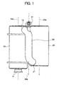
- FIGS. 1 to 3 illustrate an embodiment of an exhaust gas purification apparatus.
- This exhaust gas purification apparatus is provided in, for example, an exhaust gas system of a diesel engine, and the exhaust gas purification apparatus includes both the SCR and the PM collection filter as described above.
- the exhaust gas purification apparatus includes a first cylindrical housing 10, a second cylindrical housing 20, and a communicating pipe 30 that connects between far end portions of the housings 10 and 20.
- the first housing 10 and the second housing 20 are closely disposed such that an axis line 10a and an axis line 20a thereof are arranged substantially parallel to each other (a parallel level to the sight).
- the communicating pipe 30 is disposed such that an axis line 30a thereof is arranged substantially parallel with the axis lines 10a and 20a of the housings 10 and 20 (a parallel level to the sight).
- an inflow port 11 is formed in an end portion on an upstream side of the exhaust gas flow, and a discharge port 12 is formed in an end portion on a downstream side of the exhaust gas flow.
- the inflow port 11 is formed in an end face in the upstream side end portion
- the discharge port 12 is formed in a side face in the downstream side end portion.
- An oxidation catalytic converter 13 and a filter 14 are contained in series between the inflow port 11 and the discharge port 12. The oxidation catalytic converter 13 oxidizes nitrogen monoxide in the exhaust gas to nitrogen dioxide, the filter 14 collects PM in the exhaust gas, and the oxidation catalytic converter 13 is located on the upstream side of the filter 14 ( FIG. 3 ).
- an inflow port 21 is formed in an end portion on an upstream side of the exhaust gas flow, and a discharge port 22 is formed in an end portion on a downstream side of the exhaust gas flow.
- both the inflow port 21 and the discharge port 22 are formed in side faces in the upstream and downstream end portions.
- a reducing catalytic converter 23 and an ammonia oxidation catalytic converter 24 are contained in series between the inflow port 21 and the discharge port 22.
- the reducing catalytic converter 23 reduction-purifies nitrogen oxide with liquid reducing agent, the ammonia oxidation catalytic converter 24 oxidizes ammonia in the exhaust gas, and the reducing catalytic converter 23 is located on the upstream side of the ammonia oxidation catalytic converter 24 ( FIG. 3 ).
- the communicating pipe 30 connects between far end portions of the housings 10 and 20, that is, the discharge port 12 in the downstream side end portion of the first housing 10 and the inflow port 21 in the upstream side end portion of the second housing 20.
- the discharge port 12 and the inflow port 21 are formed in end portions located on the opposite sides of the housings 10 and 20 away from each other (namely, far end portions). Accordingly, the engine exhaust gas flows from the inflow port 11 into the first housing 10, and the exhaust gas passing through the oxidation catalytic converter 13 and the filter 14 enters the communicating pipe 30 via the discharge port 12.
- the exhaust gas passing through the communicating pipe 30 flows from the inflow port 21 into the second housing 20, and the exhaust gas passing through the reducing catalytic converter 23 and the ammonia oxidation catalytic converter 24 is discharged from the discharge port 22. That is, the flow passage of the exhaust gas from the first housing 10 through the communicating pipe 30 to the second housing 20 is folded once by the communicating pipe 30.
- the communicating pipe 30 is the straight pipe in which bent portions are formed at both ends thereof in order to be engaged to the discharge port 12 and the inflow port 21.
- a nozzle 31 is provided, and the nozzle 31 injects the liquid reducing agent toward the inside of the straight pipe portion (dotted line in FIG. 3 ). Therefore, a straight-line length enough to evenly diffuse the liquid reducing agent in the exhaust gas is secured.
- a mesh diffuser plate may be placed in order to assist the even diffusion.
- the two housings 10 and 20 are closely disposed in parallel, and a silhouette (projection area) of the housings 10 and 20 is made a compact size corresponding to a square muffler. Further, the far end portions of the two housings 10 and 20 are connected by the communicating pipe 30. Therefore, the communicating pipe 30 is accommodated in the silhouette of the two housings 10 and 20 while the length enough to evenly diffuse the liquid reducing agent is obtained, and hence, the size can be reduced in the length direction from the upstream to the downstream of the exhaust gas flow.
Landscapes
- Engineering & Computer Science (AREA)
- Chemical & Material Sciences (AREA)
- Chemical Kinetics & Catalysis (AREA)
- Combustion & Propulsion (AREA)
- Mechanical Engineering (AREA)
- General Engineering & Computer Science (AREA)
- Health & Medical Sciences (AREA)
- Toxicology (AREA)
- Materials Engineering (AREA)
- Exhaust Gas After Treatment (AREA)
- Processes For Solid Components From Exhaust (AREA)
- Exhaust Gas Treatment By Means Of Catalyst (AREA)
Claims (2)
- Abgasreinigungsvorrichtung, die Folgendes umfasst:ein erstes zylindrisches Gehäuse (10), in dem wenigstens ein Filter (14) zum Sammeln von Feststoffen in Abgas enthalten ist,ein zweites zylindrisches Gehäuse (20), in dem wenigstens ein Reduktionskatalysator (23) zur Reduktionsreinigung von Stickstoffoxid mit einem flüssigen Reduktionsmittel enthalten ist,ein Verbindungsrohr (30), das zwischen entfernten Endabschnitten jedes Gehäuses (10, 20) verbindet, undeine Düse (31), die in dem Verbindungsrohr (30) angeordnet ist und flüssiges Reduktionsmittel in das Abgas einspritzt,wobei:das erste und das zweite zylindrische Gehäuse (10, 20) eng angeordnet sind derart, dass Achsenlinien (10a, 20a) derselben im Wesentlichen parallel zueinander angeordnet sind, unddas Verbindungsrohr (30) zwischen einer Ausströmungsöffnung (12), die in einer Seitenfläche in einem stromabwärtsseitigen Endabschnitt des ersten zylindrischen Gehäuses (10) geformt ist, und einer Einströmungsöffnung (21), die in einer Seitenfläche in einem stromaufwärtsseitigen Endabschnitt des zweiten zylindrischen Gehäuses (20) geformt ist, verbindet und derart angeordnet ist, dass eine Achsenlinie (30a) desselben im Wesentlichen parallel mit den Achsenlinien (10a, 20a) der Gehäuse (10, 20) angeordnet ist, wodurch ein Strömungsdurchgang des Abgases von dem ersten Gehäuse (10) zu dem zweiten Gehäuse (20) gefaltet wird,das Verbindungsrohr (30) einen geraden Abschnitt und gebogene Abschnitte, die an den beiden Enden des geraden Abschnitts geformt sind, um mit der Ausströmungsöffnung (12) und der Einströmungsöffnung (21) in Eingriff gebracht zu werden, einschließt,die Düse (31) an dem gebogenen Abschnitt für die Ausströmungsöffnung (12) befestigt ist und das flüssige Reduktionsmittel zu einem Inneren des geraden Abschnitts hin einspritzt unddas zweite Gehäuse (20) ferner einen Ammoniak-Oxidationskatalysator (24) enthält, der auf einer Abgas-Stromabwärtsseite des Reduktionskatalysators (23) Ammoniak in dem Abgas oxidiert.
- Abgasreinigungsvorrichtung nach Anspruch 1, wobei das erste Gehäuse (10) ferner einen Oxidationskatalysator (13) enthält, der auf einer Abgas-Stromaufwärtsseite des Filters (14) Stickstoffmonoxid in dem Abgas oxidiert.
Applications Claiming Priority (2)
| Application Number | Priority Date | Filing Date | Title |
|---|---|---|---|
| JP2007254490A JP4286888B2 (ja) | 2007-09-28 | 2007-09-28 | 排気浄化装置 |
| PCT/JP2008/057816 WO2009041103A1 (ja) | 2007-09-28 | 2008-04-23 | 排気浄化装置 |
Publications (3)
| Publication Number | Publication Date |
|---|---|
| EP2199554A1 EP2199554A1 (de) | 2010-06-23 |
| EP2199554A4 EP2199554A4 (de) | 2013-03-06 |
| EP2199554B1 true EP2199554B1 (de) | 2014-12-17 |
Family
ID=40511005
Family Applications (1)
| Application Number | Title | Priority Date | Filing Date |
|---|---|---|---|
| EP08751954.2A Not-in-force EP2199554B1 (de) | 2007-09-28 | 2008-04-23 | Abgasreinigungsvorrichtungen |
Country Status (6)
| Country | Link |
|---|---|
| US (1) | US8394332B2 (de) |
| EP (1) | EP2199554B1 (de) |
| JP (1) | JP4286888B2 (de) |
| CN (1) | CN101809256A (de) |
| ES (1) | ES2526820T3 (de) |
| WO (1) | WO2009041103A1 (de) |
Families Citing this family (27)
| Publication number | Priority date | Publication date | Assignee | Title |
|---|---|---|---|---|
| JP5114219B2 (ja) * | 2008-01-10 | 2013-01-09 | 東京濾器株式会社 | 内燃機関用の排ガス浄化装置 |
| JP5449009B2 (ja) * | 2010-04-28 | 2014-03-19 | 日野自動車株式会社 | 排気浄化装置 |
| FR2972022B1 (fr) * | 2011-02-25 | 2013-03-15 | Peugeot Citroen Automobiles Sa | Vehicule automobile comportant une ligne d'echappement dont les moyens acoustiques sont disposes en avant du train arriere |
| US8916100B2 (en) | 2011-12-27 | 2014-12-23 | Komatsu Ltd. | Reducing agent aqueous solution mixing device and exhaust gas post-treatment device |
| JP5349575B2 (ja) | 2011-12-27 | 2013-11-20 | 株式会社小松製作所 | 還元剤水溶液ミキシング装置及び排気ガス後処理装置 |
| US8932530B2 (en) | 2011-12-27 | 2015-01-13 | Komatsu Ltd. | Reducing agent aqueous solution mixing device and exhaust gas post-treatment device |
| CN104040125A (zh) * | 2012-01-06 | 2014-09-10 | 沃尔沃建造设备有限公司 | 用于减少重型设备的废气的装置 |
| JP2013167158A (ja) * | 2012-02-14 | 2013-08-29 | Hino Motors Ltd | 排気浄化装置 |
| US9663366B2 (en) | 2012-03-05 | 2017-05-30 | Basf Se | Ammonia oxidation reactor with internal filter element |
| US9316136B2 (en) | 2012-07-05 | 2016-04-19 | Komatsu Ltd. | Engine unit and work vehicle |
| CN102794064A (zh) * | 2012-07-18 | 2012-11-28 | 樊荣 | 一种气体净化器 |
| US9133601B2 (en) * | 2012-10-16 | 2015-09-15 | Komatsu Ltd. | Hydraulic excavator |
| JP5728578B2 (ja) * | 2013-01-17 | 2015-06-03 | 株式会社小松製作所 | 還元剤水溶液ミキシング装置およびこれを備えた排気ガス後処理装置 |
| US8893481B2 (en) * | 2013-01-17 | 2014-11-25 | Komatsu Ltd. | Reductant aqueous solution mixing device and exhaust aftertreatment device provided with the same |
| KR101360161B1 (ko) | 2013-01-17 | 2014-02-12 | 가부시키가이샤 고마쓰 세이사쿠쇼 | 환원제 수용액 믹싱 장치 및 이것을 구비한 배기 가스 후처리 장치 |
| US8991160B2 (en) * | 2013-01-17 | 2015-03-31 | Komatsu Ltd. | Reductant aqueous solution mixing device and exhaust aftertreatment device provided with the same |
| JP6161057B2 (ja) * | 2013-02-08 | 2017-07-12 | 東京濾器株式会社 | 排気ガス浄化装置 |
| GB2515450B (en) | 2013-03-18 | 2017-03-22 | Alexander Dennis Ltd | Passenger service vehicle |
| DE102013210799C5 (de) * | 2013-06-10 | 2020-07-09 | Eberspächer Exhaust Technology GmbH & Co. KG | Abgasanlage einer Brennkraftmaschine |
| JP6190182B2 (ja) | 2013-06-28 | 2017-08-30 | 株式会社タダノ | ラフテレーンクレーン用排気浄化装置 |
| JP6347474B2 (ja) * | 2013-07-31 | 2018-06-27 | カルソニックカンセイ株式会社 | 排気浄化装置 |
| JP2015052274A (ja) * | 2013-09-05 | 2015-03-19 | ヤンマー株式会社 | 作業機搭載用エンジン装置 |
| DE102013219640A1 (de) * | 2013-09-27 | 2015-04-02 | Eberspächer Exhaust Technology GmbH & Co. KG | Abgasbehandlungseinrichtung |
| CN107002532B (zh) * | 2014-11-21 | 2019-07-09 | 株式会社Kcm | 产业用车辆 |
| JP6417920B2 (ja) | 2014-12-19 | 2018-11-07 | 株式会社タダノ | ラフテレーンクレーン |
| JP7273619B2 (ja) | 2018-06-01 | 2023-05-15 | マニタウォック クレイン カンパニーズ, エルエルシー | クレーン下部走行体上のエンジン排気後処理システムのための取り付け配設 |
| US10883411B2 (en) | 2018-06-06 | 2021-01-05 | Ford Global Technologies, Llc | Systems and methods for an exhaust-gas aftertreatment device |
Family Cites Families (13)
| Publication number | Priority date | Publication date | Assignee | Title |
|---|---|---|---|---|
| DE10042542A1 (de) * | 2000-08-30 | 2002-03-14 | Eberspaecher J Gmbh & Co | Abgasreinigungssystem für Kraftfahrzeuge, insbesondere Diesel-Nutzfahrzeuge |
| GB0220645D0 (en) * | 2002-09-05 | 2002-10-16 | Johnson Matthey Plc | Exhaust system for a lean burn ic engine |
| JP2004108221A (ja) * | 2002-09-18 | 2004-04-08 | Kubota Corp | ガスエンジン |
| DE10300298A1 (de) * | 2003-01-02 | 2004-07-15 | Daimlerchrysler Ag | Abgasnachbehandlungseinrichtung und -verfahren |
| JP2005155404A (ja) * | 2003-11-25 | 2005-06-16 | Komatsu Ltd | 内燃機関の排気ガス浄化装置 |
| US8015802B2 (en) * | 2004-11-25 | 2011-09-13 | Komatsu Ltd. | Exhaust gas purification device for internal combustion engine |
| DE102005002289B4 (de) * | 2005-01-17 | 2007-04-19 | J. Eberspächer GmbH & Co. KG | Abgasbehandlungssystem |
| JP4462556B2 (ja) | 2005-08-04 | 2010-05-12 | 三菱ふそうトラック・バス株式会社 | 内燃機関の排気浄化装置 |
| US7562522B2 (en) * | 2006-06-06 | 2009-07-21 | Eaton Corporation | Enhanced hybrid de-NOx system |
| JP4785766B2 (ja) * | 2007-02-09 | 2011-10-05 | 日野自動車株式会社 | 排気浄化装置 |
| JP4886547B2 (ja) * | 2007-02-23 | 2012-02-29 | 日野自動車株式会社 | 排気浄化装置 |
| DE202007010435U1 (de) * | 2007-07-26 | 2007-10-25 | Heinrich Gillet Gmbh | Abgasanlage für Nutzfahrzeuge |
| JP4920532B2 (ja) * | 2007-09-13 | 2012-04-18 | 日野自動車株式会社 | 排気浄化装置 |
-
2007
- 2007-09-28 JP JP2007254490A patent/JP4286888B2/ja not_active Expired - Fee Related
-
2008
- 2008-04-23 EP EP08751954.2A patent/EP2199554B1/de not_active Not-in-force
- 2008-04-23 CN CN200880109161A patent/CN101809256A/zh active Pending
- 2008-04-23 WO PCT/JP2008/057816 patent/WO2009041103A1/ja not_active Ceased
- 2008-04-23 ES ES08751954.2T patent/ES2526820T3/es active Active
-
2010
- 2010-03-25 US US12/731,736 patent/US8394332B2/en not_active Expired - Fee Related
Also Published As
| Publication number | Publication date |
|---|---|
| WO2009041103A1 (ja) | 2009-04-02 |
| EP2199554A4 (de) | 2013-03-06 |
| ES2526820T3 (es) | 2015-01-15 |
| EP2199554A1 (de) | 2010-06-23 |
| US8394332B2 (en) | 2013-03-12 |
| US20100178216A1 (en) | 2010-07-15 |
| JP4286888B2 (ja) | 2009-07-01 |
| CN101809256A (zh) | 2010-08-18 |
| JP2009085065A (ja) | 2009-04-23 |
Similar Documents
| Publication | Publication Date | Title |
|---|---|---|
| EP2199554B1 (de) | Abgasreinigungsvorrichtungen | |
| EP2202389B1 (de) | Abgasreinigungsvorrichtung | |
| US8375703B2 (en) | Exhaust gas purification device | |
| JP5114219B2 (ja) | 内燃機関用の排ガス浄化装置 | |
| KR101292627B1 (ko) | 배기 정화 장치 | |
| EP3433475B1 (de) | Abgasnachbehandlungssystem | |
| CN104040130A (zh) | 排气净化装置 | |
| GB2465151A (en) | Engine exhaust treatment unit | |
| JP4462556B2 (ja) | 内燃機関の排気浄化装置 | |
| JP5890661B2 (ja) | 排気浄化装置 | |
| US20110047986A1 (en) | Retrofit Aftertreatment System for Treating Diesel Exhaust | |
| JP5057944B2 (ja) | 排気後処理装置 | |
| JP5688963B2 (ja) | エンジンの排気浄化装置 | |
| WO2014192183A1 (ja) | 排ガス浄化装置 | |
| CA3130993A1 (en) | Diesel exhaust treatment apparatus and methods | |
| JP2012092746A (ja) | 排気浄化装置 | |
| CN115335592B (zh) | 排气净化装置 | |
| JP2009097435A (ja) | 排気浄化装置 | |
| WO2015075793A1 (ja) | 排気浄化装置及びその再生方法 | |
| JP2020516815A (ja) | 排ガスシステム | |
| JP2012002082A (ja) | 排気浄化触媒装置及び排気浄化装置 | |
| WO2018057170A1 (en) | After-treatment system | |
| JP2007247549A (ja) | 内燃機関の排気浄化装置 | |
| JP2020204286A (ja) | パイプ保温構造 |
Legal Events
| Date | Code | Title | Description |
|---|---|---|---|
| PUAI | Public reference made under article 153(3) epc to a published international application that has entered the european phase |
Free format text: ORIGINAL CODE: 0009012 |
|
| 17P | Request for examination filed |
Effective date: 20100414 |
|
| AK | Designated contracting states |
Kind code of ref document: A1 Designated state(s): AT BE BG CH CY CZ DE DK EE ES FI FR GB GR HR HU IE IS IT LI LT LU LV MC MT NL NO PL PT RO SE SI SK TR |
|
| AX | Request for extension of the european patent |
Extension state: AL BA MK RS |
|
| DAX | Request for extension of the european patent (deleted) | ||
| REG | Reference to a national code |
Ref country code: DE Ref legal event code: R079 Ref document number: 602008035902 Country of ref document: DE Free format text: PREVIOUS MAIN CLASS: F01N0003080000 Ipc: F01N0003280000 |
|
| A4 | Supplementary search report drawn up and despatched |
Effective date: 20130204 |
|
| RIC1 | Information provided on ipc code assigned before grant |
Ipc: F01N 3/035 20060101ALI20130129BHEP Ipc: F01N 3/20 20060101ALI20130129BHEP Ipc: F01N 3/28 20060101AFI20130129BHEP Ipc: F01N 3/10 20060101ALI20130129BHEP |
|
| GRAP | Despatch of communication of intention to grant a patent |
Free format text: ORIGINAL CODE: EPIDOSNIGR1 |
|
| INTG | Intention to grant announced |
Effective date: 20140804 |
|
| GRAS | Grant fee paid |
Free format text: ORIGINAL CODE: EPIDOSNIGR3 |
|
| GRAA | (expected) grant |
Free format text: ORIGINAL CODE: 0009210 |
|
| AK | Designated contracting states |
Kind code of ref document: B1 Designated state(s): AT BE BG CH CY CZ DE DK EE ES FI FR GB GR HR HU IE IS IT LI LT LU LV MC MT NL NO PL PT RO SE SI SK TR |
|
| REG | Reference to a national code |
Ref country code: GB Ref legal event code: FG4D |
|
| RIN1 | Information on inventor provided before grant (corrected) |
Inventor name: NOSAKI, MASAHITO Inventor name: KURITA, HIROYUKI Inventor name: HONDA, KOUTAROU |
|
| REG | Reference to a national code |
Ref country code: CH Ref legal event code: EP |
|
| REG | Reference to a national code |
Ref country code: IE Ref legal event code: FG4D |
|
| REG | Reference to a national code |
Ref country code: ES Ref legal event code: FG2A Ref document number: 2526820 Country of ref document: ES Kind code of ref document: T3 Effective date: 20150115 Ref country code: AT Ref legal event code: REF Ref document number: 702108 Country of ref document: AT Kind code of ref document: T Effective date: 20150115 |
|
| REG | Reference to a national code |
Ref country code: DE Ref legal event code: R096 Ref document number: 602008035902 Country of ref document: DE Effective date: 20150129 |
|
| REG | Reference to a national code |
Ref country code: NL Ref legal event code: T3 |
|
| REG | Reference to a national code |
Ref country code: SE Ref legal event code: TRGR |
|
| REG | Reference to a national code |
Ref country code: FR Ref legal event code: PLFP Year of fee payment: 8 |
|
| PG25 | Lapsed in a contracting state [announced via postgrant information from national office to epo] |
Ref country code: FI Free format text: LAPSE BECAUSE OF FAILURE TO SUBMIT A TRANSLATION OF THE DESCRIPTION OR TO PAY THE FEE WITHIN THE PRESCRIBED TIME-LIMIT Effective date: 20141217 Ref country code: NO Free format text: LAPSE BECAUSE OF FAILURE TO SUBMIT A TRANSLATION OF THE DESCRIPTION OR TO PAY THE FEE WITHIN THE PRESCRIBED TIME-LIMIT Effective date: 20150317 Ref country code: LT Free format text: LAPSE BECAUSE OF FAILURE TO SUBMIT A TRANSLATION OF THE DESCRIPTION OR TO PAY THE FEE WITHIN THE PRESCRIBED TIME-LIMIT Effective date: 20141217 |
|
| REG | Reference to a national code |
Ref country code: LT Ref legal event code: MG4D |
|
| PG25 | Lapsed in a contracting state [announced via postgrant information from national office to epo] |
Ref country code: HR Free format text: LAPSE BECAUSE OF FAILURE TO SUBMIT A TRANSLATION OF THE DESCRIPTION OR TO PAY THE FEE WITHIN THE PRESCRIBED TIME-LIMIT Effective date: 20141217 Ref country code: GR Free format text: LAPSE BECAUSE OF FAILURE TO SUBMIT A TRANSLATION OF THE DESCRIPTION OR TO PAY THE FEE WITHIN THE PRESCRIBED TIME-LIMIT Effective date: 20150318 Ref country code: LV Free format text: LAPSE BECAUSE OF FAILURE TO SUBMIT A TRANSLATION OF THE DESCRIPTION OR TO PAY THE FEE WITHIN THE PRESCRIBED TIME-LIMIT Effective date: 20141217 |
|
| REG | Reference to a national code |
Ref country code: AT Ref legal event code: MK05 Ref document number: 702108 Country of ref document: AT Kind code of ref document: T Effective date: 20141217 |
|
| PG25 | Lapsed in a contracting state [announced via postgrant information from national office to epo] |
Ref country code: CZ Free format text: LAPSE BECAUSE OF FAILURE TO SUBMIT A TRANSLATION OF THE DESCRIPTION OR TO PAY THE FEE WITHIN THE PRESCRIBED TIME-LIMIT Effective date: 20141217 Ref country code: RO Free format text: LAPSE BECAUSE OF FAILURE TO SUBMIT A TRANSLATION OF THE DESCRIPTION OR TO PAY THE FEE WITHIN THE PRESCRIBED TIME-LIMIT Effective date: 20141217 Ref country code: SK Free format text: LAPSE BECAUSE OF FAILURE TO SUBMIT A TRANSLATION OF THE DESCRIPTION OR TO PAY THE FEE WITHIN THE PRESCRIBED TIME-LIMIT Effective date: 20141217 Ref country code: EE Free format text: LAPSE BECAUSE OF FAILURE TO SUBMIT A TRANSLATION OF THE DESCRIPTION OR TO PAY THE FEE WITHIN THE PRESCRIBED TIME-LIMIT Effective date: 20141217 |
|
| PG25 | Lapsed in a contracting state [announced via postgrant information from national office to epo] |
Ref country code: IS Free format text: LAPSE BECAUSE OF FAILURE TO SUBMIT A TRANSLATION OF THE DESCRIPTION OR TO PAY THE FEE WITHIN THE PRESCRIBED TIME-LIMIT Effective date: 20150417 Ref country code: AT Free format text: LAPSE BECAUSE OF FAILURE TO SUBMIT A TRANSLATION OF THE DESCRIPTION OR TO PAY THE FEE WITHIN THE PRESCRIBED TIME-LIMIT Effective date: 20141217 Ref country code: PL Free format text: LAPSE BECAUSE OF FAILURE TO SUBMIT A TRANSLATION OF THE DESCRIPTION OR TO PAY THE FEE WITHIN THE PRESCRIBED TIME-LIMIT Effective date: 20141217 |
|
| REG | Reference to a national code |
Ref country code: DE Ref legal event code: R026 Ref document number: 602008035902 Country of ref document: DE |
|
| PLBI | Opposition filed |
Free format text: ORIGINAL CODE: 0009260 |
|
| 26 | Opposition filed |
Opponent name: TENNECO GMBH Effective date: 20150916 |
|
| PLAX | Notice of opposition and request to file observation + time limit sent |
Free format text: ORIGINAL CODE: EPIDOSNOBS2 |
|
| PG25 | Lapsed in a contracting state [announced via postgrant information from national office to epo] |
Ref country code: DK Free format text: LAPSE BECAUSE OF FAILURE TO SUBMIT A TRANSLATION OF THE DESCRIPTION OR TO PAY THE FEE WITHIN THE PRESCRIBED TIME-LIMIT Effective date: 20141217 |
|
| PG25 | Lapsed in a contracting state [announced via postgrant information from national office to epo] |
Ref country code: MC Free format text: LAPSE BECAUSE OF FAILURE TO SUBMIT A TRANSLATION OF THE DESCRIPTION OR TO PAY THE FEE WITHIN THE PRESCRIBED TIME-LIMIT Effective date: 20141217 Ref country code: LU Free format text: LAPSE BECAUSE OF FAILURE TO SUBMIT A TRANSLATION OF THE DESCRIPTION OR TO PAY THE FEE WITHIN THE PRESCRIBED TIME-LIMIT Effective date: 20150423 |
|
| REG | Reference to a national code |
Ref country code: CH Ref legal event code: PL |
|
| GBPC | Gb: european patent ceased through non-payment of renewal fee |
Effective date: 20150423 |
|
| REG | Reference to a national code |
Ref country code: IE Ref legal event code: MM4A |
|
| PG25 | Lapsed in a contracting state [announced via postgrant information from national office to epo] |
Ref country code: LI Free format text: LAPSE BECAUSE OF NON-PAYMENT OF DUE FEES Effective date: 20150430 Ref country code: GB Free format text: LAPSE BECAUSE OF NON-PAYMENT OF DUE FEES Effective date: 20150423 Ref country code: CH Free format text: LAPSE BECAUSE OF NON-PAYMENT OF DUE FEES Effective date: 20150430 |
|
| PG25 | Lapsed in a contracting state [announced via postgrant information from national office to epo] |
Ref country code: SI Free format text: LAPSE BECAUSE OF FAILURE TO SUBMIT A TRANSLATION OF THE DESCRIPTION OR TO PAY THE FEE WITHIN THE PRESCRIBED TIME-LIMIT Effective date: 20141217 |
|
| PLAF | Information modified related to communication of a notice of opposition and request to file observations + time limit |
Free format text: ORIGINAL CODE: EPIDOSCOBS2 |
|
| PLBB | Reply of patent proprietor to notice(s) of opposition received |
Free format text: ORIGINAL CODE: EPIDOSNOBS3 |
|
| REG | Reference to a national code |
Ref country code: FR Ref legal event code: PLFP Year of fee payment: 9 |
|
| RAP2 | Party data changed (patent owner data changed or rights of a patent transferred) |
Owner name: VOLVO TRUCK CORPORATION |
|
| PG25 | Lapsed in a contracting state [announced via postgrant information from national office to epo] |
Ref country code: IE Free format text: LAPSE BECAUSE OF NON-PAYMENT OF DUE FEES Effective date: 20150423 |
|
| PG25 | Lapsed in a contracting state [announced via postgrant information from national office to epo] |
Ref country code: MT Free format text: LAPSE BECAUSE OF FAILURE TO SUBMIT A TRANSLATION OF THE DESCRIPTION OR TO PAY THE FEE WITHIN THE PRESCRIBED TIME-LIMIT Effective date: 20141217 |
|
| REG | Reference to a national code |
Ref country code: FR Ref legal event code: PLFP Year of fee payment: 10 |
|
| PLAY | Examination report in opposition despatched + time limit |
Free format text: ORIGINAL CODE: EPIDOSNORE2 |
|
| PG25 | Lapsed in a contracting state [announced via postgrant information from national office to epo] |
Ref country code: HU Free format text: LAPSE BECAUSE OF FAILURE TO SUBMIT A TRANSLATION OF THE DESCRIPTION OR TO PAY THE FEE WITHIN THE PRESCRIBED TIME-LIMIT; INVALID AB INITIO Effective date: 20080423 Ref country code: BG Free format text: LAPSE BECAUSE OF FAILURE TO SUBMIT A TRANSLATION OF THE DESCRIPTION OR TO PAY THE FEE WITHIN THE PRESCRIBED TIME-LIMIT Effective date: 20141217 |
|
| PG25 | Lapsed in a contracting state [announced via postgrant information from national office to epo] |
Ref country code: CY Free format text: LAPSE BECAUSE OF FAILURE TO SUBMIT A TRANSLATION OF THE DESCRIPTION OR TO PAY THE FEE WITHIN THE PRESCRIBED TIME-LIMIT Effective date: 20141217 |
|
| PG25 | Lapsed in a contracting state [announced via postgrant information from national office to epo] |
Ref country code: PT Free format text: LAPSE BECAUSE OF FAILURE TO SUBMIT A TRANSLATION OF THE DESCRIPTION OR TO PAY THE FEE WITHIN THE PRESCRIBED TIME-LIMIT Effective date: 20150417 |
|
| PG25 | Lapsed in a contracting state [announced via postgrant information from national office to epo] |
Ref country code: TR Free format text: LAPSE BECAUSE OF FAILURE TO SUBMIT A TRANSLATION OF THE DESCRIPTION OR TO PAY THE FEE WITHIN THE PRESCRIBED TIME-LIMIT Effective date: 20141217 |
|
| PLBC | Reply to examination report in opposition received |
Free format text: ORIGINAL CODE: EPIDOSNORE3 |
|
| REG | Reference to a national code |
Ref country code: FR Ref legal event code: PLFP Year of fee payment: 11 |
|
| REG | Reference to a national code |
Ref country code: DE Ref legal event code: R100 Ref document number: 602008035902 Country of ref document: DE |
|
| PLCK | Communication despatched that opposition was rejected |
Free format text: ORIGINAL CODE: EPIDOSNREJ1 |
|
| PLBN | Opposition rejected |
Free format text: ORIGINAL CODE: 0009273 |
|
| STAA | Information on the status of an ep patent application or granted ep patent |
Free format text: STATUS: OPPOSITION REJECTED |
|
| 27O | Opposition rejected |
Effective date: 20181107 |
|
| REG | Reference to a national code |
Ref country code: DE Ref legal event code: R081 Ref document number: 602008035902 Country of ref document: DE Owner name: VOLVO TRUCK CORPORATION, SE Free format text: FORMER OWNER: UD TRUCKS CORP., AGEO-SHI, SAITAMA, JP |
|
| REG | Reference to a national code |
Ref country code: BE Ref legal event code: PD Owner name: VOLVO GROUP SWEDEN AB; SE Free format text: DETAILS ASSIGNMENT: CHANGE OF OWNER(S), ASSIGNMENT; FORMER OWNER NAME: UD TRUCKS CORPORATION Effective date: 20211018 Ref country code: BE Ref legal event code: HC Owner name: VOLVO TRUCK CORPORATION; SE Free format text: DETAILS ASSIGNMENT: CHANGE OF OWNER(S), CHANGE OF OWNER(S) NAME; FORMER OWNER NAME: VOLVO GROUP SWEDEN AB Effective date: 20211018 |
|
| REG | Reference to a national code |
Ref country code: NL Ref legal event code: PD Owner name: VOLVO TRUCK CORPORATION; SE Free format text: DETAILS ASSIGNMENT: CHANGE OF OWNER(S), ASSIGNMENT; FORMER OWNER NAME: VOLVO GROUP SWEDEN AB Effective date: 20211125 |
|
| PGFP | Annual fee paid to national office [announced via postgrant information from national office to epo] |
Ref country code: NL Payment date: 20220427 Year of fee payment: 15 |
|
| PGFP | Annual fee paid to national office [announced via postgrant information from national office to epo] |
Ref country code: SE Payment date: 20220421 Year of fee payment: 15 Ref country code: IT Payment date: 20220421 Year of fee payment: 15 Ref country code: FR Payment date: 20220427 Year of fee payment: 15 Ref country code: ES Payment date: 20220513 Year of fee payment: 15 Ref country code: DE Payment date: 20220428 Year of fee payment: 15 |
|
| PGFP | Annual fee paid to national office [announced via postgrant information from national office to epo] |
Ref country code: BE Payment date: 20220427 Year of fee payment: 15 |
|
| REG | Reference to a national code |
Ref country code: DE Ref legal event code: R119 Ref document number: 602008035902 Country of ref document: DE |
|
| REG | Reference to a national code |
Ref country code: SE Ref legal event code: EUG |
|
| REG | Reference to a national code |
Ref country code: NL Ref legal event code: MM Effective date: 20230501 |
|
| REG | Reference to a national code |
Ref country code: BE Ref legal event code: MM Effective date: 20230430 |
|
| PG25 | Lapsed in a contracting state [announced via postgrant information from national office to epo] |
Ref country code: SE Free format text: LAPSE BECAUSE OF NON-PAYMENT OF DUE FEES Effective date: 20230424 Ref country code: NL Free format text: LAPSE BECAUSE OF NON-PAYMENT OF DUE FEES Effective date: 20230501 Ref country code: FR Free format text: LAPSE BECAUSE OF NON-PAYMENT OF DUE FEES Effective date: 20230430 Ref country code: DE Free format text: LAPSE BECAUSE OF NON-PAYMENT OF DUE FEES Effective date: 20231103 |
|
| PG25 | Lapsed in a contracting state [announced via postgrant information from national office to epo] |
Ref country code: BE Free format text: LAPSE BECAUSE OF NON-PAYMENT OF DUE FEES Effective date: 20230430 |
|
| PG25 | Lapsed in a contracting state [announced via postgrant information from national office to epo] |
Ref country code: IT Free format text: LAPSE BECAUSE OF NON-PAYMENT OF DUE FEES Effective date: 20230423 |
|
| REG | Reference to a national code |
Ref country code: ES Ref legal event code: FD2A Effective date: 20240531 |
|
| PG25 | Lapsed in a contracting state [announced via postgrant information from national office to epo] |
Ref country code: ES Free format text: LAPSE BECAUSE OF NON-PAYMENT OF DUE FEES Effective date: 20230424 |
|
| PG25 | Lapsed in a contracting state [announced via postgrant information from national office to epo] |
Ref country code: ES Free format text: LAPSE BECAUSE OF NON-PAYMENT OF DUE FEES Effective date: 20230424 |