EP2199559B1 - Tuyau X et installation de gaz d'échappement correspondante - Google Patents
Tuyau X et installation de gaz d'échappement correspondante Download PDFInfo
- Publication number
- EP2199559B1 EP2199559B1 EP09175662.7A EP09175662A EP2199559B1 EP 2199559 B1 EP2199559 B1 EP 2199559B1 EP 09175662 A EP09175662 A EP 09175662A EP 2199559 B1 EP2199559 B1 EP 2199559B1
- Authority
- EP
- European Patent Office
- Prior art keywords
- pipe according
- channels
- half shells
- inlet
- housing
- Prior art date
- Legal status (The legal status is an assumption and is not a legal conclusion. Google has not performed a legal analysis and makes no representation as to the accuracy of the status listed.)
- Not-in-force
Links
Images


Classifications
-
- F—MECHANICAL ENGINEERING; LIGHTING; HEATING; WEAPONS; BLASTING
- F01—MACHINES OR ENGINES IN GENERAL; ENGINE PLANTS IN GENERAL; STEAM ENGINES
- F01N—GAS-FLOW SILENCERS OR EXHAUST APPARATUS FOR MACHINES OR ENGINES IN GENERAL; GAS-FLOW SILENCERS OR EXHAUST APPARATUS FOR INTERNAL-COMBUSTION ENGINES
- F01N13/00—Exhaust or silencing apparatus characterised by constructional features
- F01N13/08—Other arrangements or adaptations of exhaust conduits
-
- F—MECHANICAL ENGINEERING; LIGHTING; HEATING; WEAPONS; BLASTING
- F01—MACHINES OR ENGINES IN GENERAL; ENGINE PLANTS IN GENERAL; STEAM ENGINES
- F01N—GAS-FLOW SILENCERS OR EXHAUST APPARATUS FOR MACHINES OR ENGINES IN GENERAL; GAS-FLOW SILENCERS OR EXHAUST APPARATUS FOR INTERNAL-COMBUSTION ENGINES
- F01N13/00—Exhaust or silencing apparatus characterised by constructional features
- F01N13/18—Construction facilitating manufacture, assembly, or disassembly
- F01N13/1872—Construction facilitating manufacture, assembly, or disassembly the assembly using stamp-formed parts or otherwise deformed sheet-metal
- F01N13/1877—Construction facilitating manufacture, assembly, or disassembly the assembly using stamp-formed parts or otherwise deformed sheet-metal the channels or tubes thereof being made integrally with the housing
-
- F—MECHANICAL ENGINEERING; LIGHTING; HEATING; WEAPONS; BLASTING
- F01—MACHINES OR ENGINES IN GENERAL; ENGINE PLANTS IN GENERAL; STEAM ENGINES
- F01N—GAS-FLOW SILENCERS OR EXHAUST APPARATUS FOR MACHINES OR ENGINES IN GENERAL; GAS-FLOW SILENCERS OR EXHAUST APPARATUS FOR INTERNAL-COMBUSTION ENGINES
- F01N13/00—Exhaust or silencing apparatus characterised by constructional features
- F01N13/18—Construction facilitating manufacture, assembly, or disassembly
- F01N13/1888—Construction facilitating manufacture, assembly, or disassembly the housing of the assembly consisting of two or more parts, e.g. two half-shells
-
- F—MECHANICAL ENGINEERING; LIGHTING; HEATING; WEAPONS; BLASTING
- F01—MACHINES OR ENGINES IN GENERAL; ENGINE PLANTS IN GENERAL; STEAM ENGINES
- F01N—GAS-FLOW SILENCERS OR EXHAUST APPARATUS FOR MACHINES OR ENGINES IN GENERAL; GAS-FLOW SILENCERS OR EXHAUST APPARATUS FOR INTERNAL-COMBUSTION ENGINES
- F01N2470/00—Structure or shape of exhaust gas passages, pipes or tubes
- F01N2470/06—Tubes being formed by assembly of stamped or otherwise deformed sheet-metal
-
- F—MECHANICAL ENGINEERING; LIGHTING; HEATING; WEAPONS; BLASTING
- F01—MACHINES OR ENGINES IN GENERAL; ENGINE PLANTS IN GENERAL; STEAM ENGINES
- F01N—GAS-FLOW SILENCERS OR EXHAUST APPARATUS FOR MACHINES OR ENGINES IN GENERAL; GAS-FLOW SILENCERS OR EXHAUST APPARATUS FOR INTERNAL-COMBUSTION ENGINES
- F01N2470/00—Structure or shape of exhaust gas passages, pipes or tubes
- F01N2470/14—Plurality of outlet tubes, e.g. in parallel or with different length
-
- F—MECHANICAL ENGINEERING; LIGHTING; HEATING; WEAPONS; BLASTING
- F01—MACHINES OR ENGINES IN GENERAL; ENGINE PLANTS IN GENERAL; STEAM ENGINES
- F01N—GAS-FLOW SILENCERS OR EXHAUST APPARATUS FOR MACHINES OR ENGINES IN GENERAL; GAS-FLOW SILENCERS OR EXHAUST APPARATUS FOR INTERNAL-COMBUSTION ENGINES
- F01N2470/00—Structure or shape of exhaust gas passages, pipes or tubes
- F01N2470/16—Plurality of inlet tubes, e.g. discharging into different chambers
Definitions
- the present invention relates to an X-tube for an at least partially double-flow exhaust system of an internal combustion engine, in particular of a motor vehicle.
- the invention also relates to an exhaust system for an internal combustion engine, in particular a motor vehicle, which is equipped with such an X-tube.
- X-tubes which can also be referred to as X-pants, are used in exhaust systems, which are designed at least partially double-flow, to couple the two parallel-flow exhaust pipes of the double-flow section with each other. This coupling should allow a pressure equalization and in particular a sound pressure equalization between the two exhaust pipes, so that an exchange of airborne sound between the two exhaust pipes takes place.
- such an X-tube such as in the DE 103 54 699 1, a housing, which has two inlet openings for two coming sections of the two exhaust pipes on one inlet side and two outlet openings for two outgoing sections of the two exhaust pipes on one outlet side.
- a space enclosed by the housing interior, with which the openings are communicatively connected then takes place the desired pressure equalization or the desired sound transmission.
- the present invention is concerned with the problem of providing an improved embodiment for an X-tube or for an exhaust system equipped therewith, which is characterized in particular by the fact that the X-tube has a comparatively low flow resistance and is inexpensive to manufacture.
- the invention is based on the general idea to produce the housing from two half-shells and to arrange in the interior a permeable to airborne sound, which divides the interior into two parallel-flow channels. Through the bottom, the two separate flow-through channels can communicate with each other in terms of pressure transmission as well as airborne transmission. In principle, a gas exchange is possible.
- the channeling of the interior with the help of the floor reduces the flow resistance of the X-pipe.
- the fact that for the realization of the X-tube presented here basically only three components are required, namely the two half-shells and the bottom, is particularly advantageous. This makes the production of the X-tube extremely cheap.
- the half-shells between the channels each have a receiving groove into which the bottom is inserted with its longitudinal ends. As a result, a positive fixing or positioning of the bottom is realized in the half-shells.
- the half-shells between the channels each have two inwardly projecting, parallel to each other extending longitudinal beads, which form the respective receiving groove in the interior between them.
- the grooves can be formed particularly inexpensive.
- the beads lead to a stiffening of the half shells in the area of the soil.
- the base may have, on a side facing one of the channels, a collar which extends peripherally and protrudes toward the said channel.
- the two half-shells can be designed as identical parts. This means that both shells are identical. This design means that ultimately only two different components must be used to produce the X-tube, namely the two same half shells and the one bottom. The production costs can be further reduced.
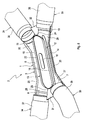
- Fig. 1 to 8 includes an X-tube 1, which accordingly Fig. 8 can be used in an at least partially double-flow exhaust system 2, a housing 3, which is assembled from two half-shells 4, 5.
- the two half-shells 4, 5 can be configured in accordance with an advantageous embodiment as equal parts. Both half-shells 4, 5 are then identical.
- the housing 3 has two inlet openings, namely a first inlet opening 7 and a second inlet opening 8, on an inlet side 6.
- the housing 3 has two outlet openings, namely a first outlet opening 10 and a second outlet opening 11.
- the housing 3 encloses an inner space 12, which communicates with the openings 7, 8, 10, 11 communicating.
- a bottom 13 is arranged. This forms with respect to the two half-shells 4, 5 a separate component. He subdivides the interior 12 into two channels, namely a first channel 14 and a second channel 15. The division of the interior 12 into the two channels 14, 15 takes place in such a way that each channel 14, 15 with an inlet opening 7, 8 and an outlet opening 10, 11 is communicatively connected.
- the first channel 14 is communicatively connected to the first inlet port 7 and to the first outlet port 10, while the first channel 14 communicates with the first channel second channel 15 is communicatively connected to the second inlet opening 8 and to the second outlet opening 11.
- the bottom 13 is made permeable to airborne sound. It connects the two channels 14, 15 with respect to an airborne sound transmission.
- the bottom 13 includes a passage opening 16 through which the two channels 14, 15 are communicatively connected to each other.
- the passage opening 16 is purely exemplary here. Although it forms a preferred embodiment, but may in principle be formed by a perforation. Likewise, gill-shaped openings are conceivable, which are open or closed against the flow direction and, for example, reduce flow noise.
- the bottom 13 can be provided with an aerodynamically optimized slot with regard to flow noise and resistance.
- the two half-shells 4, 5 have according to the preferred embodiment shown here between the channels 14, 15 each have a receiving groove 17.
- the two grooves 17 are located in the interior 12 opposite and together form a receptacle into which the bottom 13 is inserted with its longitudinal ends 18.
- the half-shells 4, 5 each have on their outer sides two inwardly projecting, mutually parallel longitudinal corrugations 19.
- the two longitudinal beads 19 are spaced apart from each other, so that they form the respective receiving groove 17 between them.
- the longitudinal corrugations 19 form an intensive stiffening of the respective half-shell 4, 5 in the region of the bottom 13.
- the bottom 13 is fixed in position in the housing 3. This fixation can be realized by a tension with the half shells 4, 5. The fixation then takes place exclusively by adhesion or frictional engagement.
- a welded joint or a solder joint of the bottom 13 with at least one of the half-shells 4, 5 may be provided to fix the bottom 13 in the housing 3 with respect to its position or position.
- the tension of the bottom 13 when connecting the two half-shells 4, 5 are realized together.
- the two half shells 4, 5 are welded together along outwardly projecting flange webs 20.
- the bottom 13 can also be welded from the outside through the respective half-shell 4, 5 through to the respective half-shell 4, 5.
- the bottom 13 is designed so that it extends in one plane.
- the plane of the bottom 13 extends parallel to the two channels 14, 15.
- the two channels 14, 15 extend in each case parallel to each other and each parallel to a prevailing in the respective channel 14, 15 main flow direction 21, the Fig. 2 indicated by arrows.
- the plane of the bottom 13 extends perpendicular to a parting plane in which the two half-shells 4, 5 are fastened to each other.
- This parting plane can in particular form a plane of symmetry for the two half-shells 4, 5.
- the parting plane of the half-shells 4, 5 can also form a plane of symmetry for the bottom 13, if it is mirror-symmetrical in shape according to the embodiment shown here with respect to this parting plane.
- the flow paths within the X-tube 1 have an X-shaped contour, which leads to the term "X-tube” or "X-pants".
- the bottom 13 can according to the preferred embodiment shown here on one side, the one of the channels 14, 15, here the first Channel 14 faces, having a collar 22 which is configured peripherally completely circumferential. Furthermore, the collar 22 to said channel 14, 15, so here to the first channel 14 out of the rest of the bottom 13 and 13 from the plane of the bottom. According to the Fig. 2 . 7 and 8th the collar 22 is flattened on the inlet side and the outlet side in the preferred embodiment presented here. This means that the height of the collar 22, with which the collar 22 protrudes from the rest of the bottom 13 or from the plane of the bottom 13, on the inlet side and outlet side is smaller than in a central portion.
- the collar height from the central portion to an inlet end 23 of the bottom 13 as well as to an outlet end 24 of the bottom 13 decreases unrestrained and in particular steadily.
- This height decrease takes place starting from both longitudinal ends 18 of the bottom 13 and - as mentioned above - preferably mirror-symmetrical to the parting plane of the half-shells 4, 5.
- the bottom 13 has an oval plan, which comprises a rectangular central portion 25 and two semicircular end portions 26.
- the flats of the collar 22 are preferably formed exclusively in the end portions 26.
- the single passage opening 16 is formed congruent to the bottom 13 and accordingly also has an oval opening cross-section.
- the housing 3 includes two inlet portions, namely, a first inlet portion 27 that includes the first inlet port 7 and communicates with the first channel 14, and a second inlet portion 28 that includes the second inlet port and communicates with the second channel 15. Furthermore, the housing 3 has two outlet sections, namely a first outlet section 29, which comprises the first outlet opening 10 and communicates with the first channel 14, and a second outlet portion 30 which includes the second outlet port 11 and communicates with the second channel 15 communicatively.
- the inlet sections 27, 28 and the outlet sections 29, 30 are each formed in half on the half-shells 4, 5. Likewise, the half shells 4, 5 each form only half of the openings 7, 8, 10, 11, which are completed only when assembled housing 3 to complete openings 7, 8, 10, 11.
- the half-shells 4, 5 each have on the inlet side 6 and on the outlet side 9 a connecting web 31 and 32, respectively.
- four such connecting webs are provided, namely two inlet-side connecting webs 31 and two outlet-side connecting webs 32.
- the connecting webs 31, 32 are located In each case two connecting webs 31, 32, namely the two inlet-side connecting webs 31 and the two outlet-side connecting webs 32 lie flat against each other, in the parting plane.
- the two half-shells 4, 5 are also fastened to one another in the region of these connecting webs 31, 32, for example by means of a welded connection or by means of a soldered connection.
- the X-tube 1 comprises exactly three components, namely the two half-shells 4, 5 and the bottom 13, wherein the two half-shells 4, 5 may also still be identical parts, so that in total only two different components are required to the X tube 1 manufacture.
- Corresponding Fig. 8 comprises the exhaust system 2, with the aid of which exhaust gases can be removed from an internal combustion engine, which can not be shown in particular in a motor vehicle, two parallelteurströmbare exhaust pipes, namely a first exhaust pipe 33 and a second exhaust pipe 34.
- the two exhaust pipes 33, 34 form one Double-flow section of the exhaust system 2. They can be flowed through in parallel and they are coupled together via the X-tube 1.
- an inlet section 35 of the first exhaust pipe 33 is connected to the first inlet opening 7 of the X-tube 1.
- An outlet portion 36 of the first exhaust pipe 33 is connected to the first exhaust port 10 of the X-pipe 1.
- An inlet portion 37 of the second exhaust pipe 34 is connected to the second inlet port 8.
- An outlet portion 38 of the second exhaust pipe 34 is connected to the second exhaust port 11.
- the X-tube 1 allows an airborne sound transmission coupling of the two exhaust gas streams within the two exhaust pipes 33, 34, without generating a significant increase in pressure in the exhaust gas streams.
Landscapes
- Engineering & Computer Science (AREA)
- Chemical & Material Sciences (AREA)
- Combustion & Propulsion (AREA)
- Mechanical Engineering (AREA)
- General Engineering & Computer Science (AREA)
- Exhaust Silencers (AREA)
Claims (12)
- Tuyau en X pour une installation de gaz d'échappement (2) au moins partiellement à double flux d'un moteur à combustion interne, notamment d'un véhicule automobile,- comportant un logement (3), qui présente sur son côté d'admission (6) deux ouvertures d'admission (7, 8) et sur son côté d'échappement (9) deux ouvertures d'échappement (10, 11),- comportant un espace interne (12) qui est enveloppé par le logement (3) et avec lequel les ouvertures (7, 8, 10, 11) sont reliées de manière communicante,- comportant une base (13), qui divise l'espace interne (12) en deux canaux (14, 15), qui sont respectivement reliés de manière communicante à une ouverture d'admission (7, 8) et à une ouverture d'échappement (10, 11),- dans lequel la base (13) est conçue de manière à laisser passer les bruits ariens et relie les deux canaux (14, 15) de manière à transmettre les bruits aériens,caractérisé en ce que- le logement (3) est constitué de deux demi-coques (4, 5),- la base (13) est conçue par rapport aux deux demi-coques (4, 5) comme un composant séparé,- les demi-coques (4, 5) présentent entre les canaux (14, 15) respectivement deux nervurages longitudinaux (19) dépassant vers l'intérieur, s'étendant parallèlement l'un à l'autre, qui définissent entre eux un espace de réception (17) dans l'espace interne (12), dans lequel la base (13) est insérée par ses extrémités longitudinales (18).
- Tuyau en X selon la revendication 1,
caractérisé en ce que
la base (13) est fixée en position dans le logement (3) et par un haubanage avec les demi-coques (4, 5) ou par une liaison de soudure avec au moins une des demi-coques (4, 5). - Tuyau en X selon une des revendications 1 et 2,
caractérisé en ce que
la base (13) s'étend dans un plan qui s'étend parallèlement aux directions d'écoulement principal (21) parallèles l'une à l'autre, prédominantes dans les deux canaux (14, 15) et a un cours perpendiculaire à un plan de séparation, dans lequel les demi-coques (4, 5) sont fixées l'une à l'autre. - Tuyau en X selon une des revendications 1 à 3,
caractérisé en ce que
la base (13) présente sur un côté tourné vers les canaux (14) un collier (22) faisant le tour de sa circonférence, dépassant en saillie vers ce canal (14). - Tuyau en X selon la revendication 4,
caractérisé en ce que
le collier (22) est aplati du côté d'admission et du côté d'échappement. - Tuyau en X selon une des revendications 1 à 5,
caractérisé en ce que
la base (13) possède une forme en plan ovale avec une portion centrale (25) rectangulaire et deux portions d'extrémité (26) en forme de demi-cercle. - Tuyau en X selon les revendications 5 et 6,
caractérisé en ce que
les aplatissements sont réalisés respectivement exclusivement dans les portions d'extrémité (26). - Tuyau en X selon une des revendications 1 à 7,
caractérisé en ce que
la base (13) est formée symétriquement par rapport à un plan de séparation, dans lequel les demi-coques (4, 5) sont fixées l'une à l'autre. - Tuyau en X selon une des revendications 1 à 8,
caractérisé en ce que
les deux demi-coques (4, 5) sont conçues comme des pièces identiques. - Tuyau en X selon une des revendications 1 à 9,
caractérisé en ce que- sur le logement (3) deux portions d'admission (27, 28) sont réalisées, qui relient respectivement une des ouvertures d'admission (7, 8) avec un des canaux (14, 15),- sur le logement (3) deux portions d'échappement (29, 30) sont réalisées, qui relient respectivement une des ouvertures d'échappement (10, 11) avec un des canaux (14, 15). - Tuyau en X selon une des revendications 1 à 10,
caractérisé en ce que
les demi-coques (4, 5) présentent sur le côté d'admission (6) et le côté d'échappement (9) à l'extérieur de l'espace interne (12) respectivement un gradin de liaison (31, 32), qui viennent reposer l'un sur l'autre en intégralité. - Installation de gaz d'échappement pour un moteur à combustion interne, notamment d'un véhicule automobile, comportant deux conduites de gaz d'échappement (33, 34) traversées parallèlement par un écoulement, qui sont couplées l'une à l'autre par l'intermédiaire d'un tuyau en X (1) selon une des revendications 1 à 11.
Applications Claiming Priority (1)
| Application Number | Priority Date | Filing Date | Title |
|---|---|---|---|
| DE102008061829A DE102008061829A1 (de) | 2008-12-11 | 2008-12-11 | X-Rohr und zugehörige Abgasanlage |
Publications (2)
| Publication Number | Publication Date |
|---|---|
| EP2199559A1 EP2199559A1 (fr) | 2010-06-23 |
| EP2199559B1 true EP2199559B1 (fr) | 2013-06-12 |
Family
ID=41533337
Family Applications (1)
| Application Number | Title | Priority Date | Filing Date |
|---|---|---|---|
| EP09175662.7A Not-in-force EP2199559B1 (fr) | 2008-12-11 | 2009-11-11 | Tuyau X et installation de gaz d'échappement correspondante |
Country Status (4)
| Country | Link |
|---|---|
| US (1) | US8209972B2 (fr) |
| EP (1) | EP2199559B1 (fr) |
| CN (1) | CN101761378B (fr) |
| DE (1) | DE102008061829A1 (fr) |
Families Citing this family (11)
| Publication number | Priority date | Publication date | Assignee | Title |
|---|---|---|---|---|
| DE102010062049A1 (de) * | 2010-11-26 | 2012-05-31 | J. Eberspächer GmbH & Co. KG | Schalldämpfer |
| CN102619607A (zh) * | 2012-04-11 | 2012-08-01 | 宁波市鄞州吉士汽配有限公司 | 一种汽车排气管 |
| US10184484B2 (en) | 2016-02-11 | 2019-01-22 | Borgwarner Inc. | Single inlet/outlet connection for turbocharger compressor |
| US11746688B1 (en) | 2018-10-27 | 2023-09-05 | David Akiba Borla | Cross-pipe exhaust assembly |
| USD887930S1 (en) | 2018-10-27 | 2020-06-23 | David Akiba Borla | Exhaust crossover assembly |
| US11326501B2 (en) | 2018-10-27 | 2022-05-10 | David Akiba Borla | Cross-pipe exhaust system |
| CN109532412A (zh) * | 2018-12-14 | 2019-03-29 | 无锡曙光模具有限公司 | 一种汽车出气半壳及其加工工艺 |
| US11692470B2 (en) * | 2019-06-07 | 2023-07-04 | Tenneco Automotive Operating Company Inc. | Exhaust system and muffler |
| US11661882B1 (en) * | 2020-06-23 | 2023-05-30 | Normand A. St. Pierre | Modified exhaust system with oxygen sensor |
| US11598236B2 (en) * | 2020-09-28 | 2023-03-07 | Ford Global Technologies, Llc | Exhaust system |
| USD1035523S1 (en) | 2023-01-06 | 2024-07-16 | David Akiba Borla | Exhaust muffler for an internal combustion engine |
Family Cites Families (17)
| Publication number | Priority date | Publication date | Assignee | Title |
|---|---|---|---|---|
| US3072214A (en) * | 1958-02-14 | 1963-01-08 | Oldberg Mfg Company | Gas blending and sound-attenuating system and apparatus |
| DE6912770U (de) * | 1969-03-28 | 1969-08-14 | Gillet Gmbh Paul | Rohrverbindung fuer doppelrohr-auspuffanlagen |
| JPS6088816A (ja) * | 1983-10-20 | 1985-05-18 | Nissan Motor Co Ltd | 内燃機関用排気管 |
| DE3740238A1 (de) * | 1986-12-04 | 1988-06-23 | Audi Ag | Abgasanlage fuer eine brennkraftmaschine mit zwei zylinderbaenken |
| US5018349A (en) * | 1989-07-31 | 1991-05-28 | Pemberton Joseph H | Exhaust efficiency increasing apparatus |
| US5144799A (en) * | 1991-07-18 | 1992-09-08 | Barth Randolph S | Crossfire calibrated exhaust system |
| US5740671A (en) * | 1997-04-01 | 1998-04-21 | Jones; Mack L. | Balance box exhaust accelerator |
| US6247305B1 (en) * | 1999-10-07 | 2001-06-19 | Darryl C. Bassani | Motorcycle exhaust system |
| US6889499B2 (en) * | 2001-05-16 | 2005-05-10 | Darryl C. Bassani | Internal combustion engine exhaust system |
| DE10331620A1 (de) * | 2003-07-12 | 2005-02-03 | Daimlerchrysler Ag | Vorrichtung zur Geräuschgestaltung bei einem Kraftfahrzeug |
| DE10354699B4 (de) * | 2003-11-22 | 2012-06-21 | Dr. Ing. H.C. F. Porsche Aktiengesellschaft | Abgasschalldämpfer für Brennkraftmaschinen |
| JP2006152806A (ja) * | 2004-11-25 | 2006-06-15 | Aisan Ind Co Ltd | 自動二輪車の排気管構造 |
| DE102005052619B4 (de) * | 2005-11-02 | 2012-10-18 | J. Eberspächer GmbH & Co. KG | Schalldämpfer für eine Abgasanlage |
| US7565800B2 (en) * | 2005-06-13 | 2009-07-28 | Wescast Industries, Inc. | Exhaust components including high temperature divider plate assemblies |
| WO2007012952A1 (fr) * | 2005-07-29 | 2007-02-01 | Toyota Jidosha Kabushiki Kaisha | Système d'épuration des gaz d'échappement pour moteur à combustion interne |
| DE102005046316A1 (de) * | 2005-09-27 | 2007-04-12 | J. Eberspächer GmbH & Co. KG | Mischglied für eine Abgasanlage |
| DE102007030038A1 (de) * | 2007-06-27 | 2009-01-02 | Faurecia Abgastechnik Gmbh | Abgasanlage für einen Verbrennungsmotor |
-
2008
- 2008-12-11 DE DE102008061829A patent/DE102008061829A1/de not_active Withdrawn
-
2009
- 2009-11-11 EP EP09175662.7A patent/EP2199559B1/fr not_active Not-in-force
- 2009-12-10 US US12/635,075 patent/US8209972B2/en active Active
- 2009-12-11 CN CN2009102524814A patent/CN101761378B/zh active Active
Also Published As
| Publication number | Publication date |
|---|---|
| US20100146955A1 (en) | 2010-06-17 |
| CN101761378A (zh) | 2010-06-30 |
| DE102008061829A1 (de) | 2010-07-08 |
| EP2199559A1 (fr) | 2010-06-23 |
| CN101761378B (zh) | 2013-03-27 |
| US8209972B2 (en) | 2012-07-03 |
Similar Documents
| Publication | Publication Date | Title |
|---|---|---|
| EP2199559B1 (fr) | Tuyau X et installation de gaz d'échappement correspondante | |
| EP2718550B1 (fr) | Silencieux et procédé de fabrication dudit silencieux | |
| DE102010019959A1 (de) | Schalldämpfer | |
| AT514568B1 (de) | Schalldämpfer | |
| WO2016016052A1 (fr) | Boîtier de soupape et soupape | |
| WO2004025196A1 (fr) | Condenseur d'agent refrigerant, notamment pour installations de conditionnement d'air d'automobile | |
| DE102007007600A1 (de) | Schalldämpfer für eine Abgasanlage | |
| DE102021113611A1 (de) | Schallminderer, Verfahren zu dessen Herstellung und Fluidleitungssystem mit einem solchen Schallminderer | |
| EP3921551B1 (fr) | Équerre de liaison par communication fluidique de conduits de fluide d'un véhicule | |
| EP1788216B1 (fr) | Liaison intermédiaire pour dispositif d'échappement | |
| EP1589311B1 (fr) | Echangeur de chaleur, en particulier pour véhicule automobile | |
| DE102013106075A1 (de) | Vorrichtung zum schwingungsentkoppelten Verbinden zweier Einrichtungen einer Abgasanlage | |
| DE10144015A1 (de) | Abgasanlage für mehrzylindrige Verbrennungsmotoren | |
| DE102005052619B4 (de) | Schalldämpfer für eine Abgasanlage | |
| EP1375848B1 (fr) | Dispositif permettant de réduire les émissions sonores et méthode pour la réalisation d'un tel dispositif | |
| DE102024208060A1 (de) | Dual-modus-schalldämpfer | |
| WO2021175717A1 (fr) | Système d'échappement et véhicule | |
| WO2020148129A1 (fr) | Procédé de fabrication d'un silencieux, silencieux et véhicule | |
| DE102014008702B4 (de) | Filter mit schräger Dichtungsebene | |
| DE202019102166U1 (de) | Angesteuertes Ventil für eine Abgasleitung | |
| DE102011089852A1 (de) | Hybridflansch | |
| DE102007063641B4 (de) | Verbindungsanordnung für den Installationsbereich | |
| DE102012218141A1 (de) | Krümmermodul | |
| DE102016110998A1 (de) | Drosselklappenanordnung und Verfahren zur Herstellung einer Drosselklappenanordnung | |
| DE102013100366A1 (de) | Doppelwandiges Abgasvolumen und entsprechendes Herstellungsverfahren |
Legal Events
| Date | Code | Title | Description |
|---|---|---|---|
| PUAI | Public reference made under article 153(3) epc to a published international application that has entered the european phase |
Free format text: ORIGINAL CODE: 0009012 |
|
| AK | Designated contracting states |
Kind code of ref document: A1 Designated state(s): AT BE BG CH CY CZ DE DK EE ES FI FR GB GR HR HU IE IS IT LI LT LU LV MC MK MT NL NO PL PT RO SE SI SK SM TR |
|
| AX | Request for extension of the european patent |
Extension state: AL BA RS |
|
| 17P | Request for examination filed |
Effective date: 20101223 |
|
| 17Q | First examination report despatched |
Effective date: 20120228 |
|
| GRAP | Despatch of communication of intention to grant a patent |
Free format text: ORIGINAL CODE: EPIDOSNIGR1 |
|
| GRAS | Grant fee paid |
Free format text: ORIGINAL CODE: EPIDOSNIGR3 |
|
| GRAA | (expected) grant |
Free format text: ORIGINAL CODE: 0009210 |
|
| AK | Designated contracting states |
Kind code of ref document: B1 Designated state(s): AT BE BG CH CY CZ DE DK EE ES FI FR GB GR HR HU IE IS IT LI LT LU LV MC MK MT NL NO PL PT RO SE SI SK SM TR |
|
| RAP1 | Party data changed (applicant data changed or rights of an application transferred) |
Owner name: EBERSPAECHER EXHAUST TECHNOLOGY GMBH & CO. KG |
|
| REG | Reference to a national code |
Ref country code: GB Ref legal event code: FG4D Free format text: NOT ENGLISH |
|
| REG | Reference to a national code |
Ref country code: CH Ref legal event code: EP |
|
| REG | Reference to a national code |
Ref country code: AT Ref legal event code: REF Ref document number: 616773 Country of ref document: AT Kind code of ref document: T Effective date: 20130615 |
|
| REG | Reference to a national code |
Ref country code: IE Ref legal event code: FG4D Free format text: LANGUAGE OF EP DOCUMENT: GERMAN |
|
| REG | Reference to a national code |
Ref country code: DE Ref legal event code: R096 Ref document number: 502009007326 Country of ref document: DE Effective date: 20130808 |
|
| PG25 | Lapsed in a contracting state [announced via postgrant information from national office to epo] |
Ref country code: SE Free format text: LAPSE BECAUSE OF FAILURE TO SUBMIT A TRANSLATION OF THE DESCRIPTION OR TO PAY THE FEE WITHIN THE PRESCRIBED TIME-LIMIT Effective date: 20130612 Ref country code: ES Free format text: LAPSE BECAUSE OF FAILURE TO SUBMIT A TRANSLATION OF THE DESCRIPTION OR TO PAY THE FEE WITHIN THE PRESCRIBED TIME-LIMIT Effective date: 20130923 Ref country code: SI Free format text: LAPSE BECAUSE OF FAILURE TO SUBMIT A TRANSLATION OF THE DESCRIPTION OR TO PAY THE FEE WITHIN THE PRESCRIBED TIME-LIMIT Effective date: 20130612 Ref country code: NO Free format text: LAPSE BECAUSE OF FAILURE TO SUBMIT A TRANSLATION OF THE DESCRIPTION OR TO PAY THE FEE WITHIN THE PRESCRIBED TIME-LIMIT Effective date: 20130912 Ref country code: LT Free format text: LAPSE BECAUSE OF FAILURE TO SUBMIT A TRANSLATION OF THE DESCRIPTION OR TO PAY THE FEE WITHIN THE PRESCRIBED TIME-LIMIT Effective date: 20130612 Ref country code: GR Free format text: LAPSE BECAUSE OF FAILURE TO SUBMIT A TRANSLATION OF THE DESCRIPTION OR TO PAY THE FEE WITHIN THE PRESCRIBED TIME-LIMIT Effective date: 20130913 Ref country code: FI Free format text: LAPSE BECAUSE OF FAILURE TO SUBMIT A TRANSLATION OF THE DESCRIPTION OR TO PAY THE FEE WITHIN THE PRESCRIBED TIME-LIMIT Effective date: 20130612 |
|
| REG | Reference to a national code |
Ref country code: NL Ref legal event code: VDEP Effective date: 20130612 |
|
| REG | Reference to a national code |
Ref country code: LT Ref legal event code: MG4D |
|
| PG25 | Lapsed in a contracting state [announced via postgrant information from national office to epo] |
Ref country code: HR Free format text: LAPSE BECAUSE OF FAILURE TO SUBMIT A TRANSLATION OF THE DESCRIPTION OR TO PAY THE FEE WITHIN THE PRESCRIBED TIME-LIMIT Effective date: 20130612 Ref country code: BG Free format text: LAPSE BECAUSE OF FAILURE TO SUBMIT A TRANSLATION OF THE DESCRIPTION OR TO PAY THE FEE WITHIN THE PRESCRIBED TIME-LIMIT Effective date: 20130912 |
|
| PG25 | Lapsed in a contracting state [announced via postgrant information from national office to epo] |
Ref country code: LV Free format text: LAPSE BECAUSE OF FAILURE TO SUBMIT A TRANSLATION OF THE DESCRIPTION OR TO PAY THE FEE WITHIN THE PRESCRIBED TIME-LIMIT Effective date: 20130612 |
|
| PG25 | Lapsed in a contracting state [announced via postgrant information from national office to epo] |
Ref country code: IS Free format text: LAPSE BECAUSE OF FAILURE TO SUBMIT A TRANSLATION OF THE DESCRIPTION OR TO PAY THE FEE WITHIN THE PRESCRIBED TIME-LIMIT Effective date: 20131012 Ref country code: CZ Free format text: LAPSE BECAUSE OF FAILURE TO SUBMIT A TRANSLATION OF THE DESCRIPTION OR TO PAY THE FEE WITHIN THE PRESCRIBED TIME-LIMIT Effective date: 20130612 Ref country code: EE Free format text: LAPSE BECAUSE OF FAILURE TO SUBMIT A TRANSLATION OF THE DESCRIPTION OR TO PAY THE FEE WITHIN THE PRESCRIBED TIME-LIMIT Effective date: 20130612 Ref country code: PT Free format text: LAPSE BECAUSE OF FAILURE TO SUBMIT A TRANSLATION OF THE DESCRIPTION OR TO PAY THE FEE WITHIN THE PRESCRIBED TIME-LIMIT Effective date: 20131014 Ref country code: SK Free format text: LAPSE BECAUSE OF FAILURE TO SUBMIT A TRANSLATION OF THE DESCRIPTION OR TO PAY THE FEE WITHIN THE PRESCRIBED TIME-LIMIT Effective date: 20130612 |
|
| PG25 | Lapsed in a contracting state [announced via postgrant information from national office to epo] |
Ref country code: RO Free format text: LAPSE BECAUSE OF FAILURE TO SUBMIT A TRANSLATION OF THE DESCRIPTION OR TO PAY THE FEE WITHIN THE PRESCRIBED TIME-LIMIT Effective date: 20130612 Ref country code: NL Free format text: LAPSE BECAUSE OF FAILURE TO SUBMIT A TRANSLATION OF THE DESCRIPTION OR TO PAY THE FEE WITHIN THE PRESCRIBED TIME-LIMIT Effective date: 20130612 Ref country code: PL Free format text: LAPSE BECAUSE OF FAILURE TO SUBMIT A TRANSLATION OF THE DESCRIPTION OR TO PAY THE FEE WITHIN THE PRESCRIBED TIME-LIMIT Effective date: 20130612 |
|
| PLBE | No opposition filed within time limit |
Free format text: ORIGINAL CODE: 0009261 |
|
| STAA | Information on the status of an ep patent application or granted ep patent |
Free format text: STATUS: NO OPPOSITION FILED WITHIN TIME LIMIT |
|
| PG25 | Lapsed in a contracting state [announced via postgrant information from national office to epo] |
Ref country code: DK Free format text: LAPSE BECAUSE OF FAILURE TO SUBMIT A TRANSLATION OF THE DESCRIPTION OR TO PAY THE FEE WITHIN THE PRESCRIBED TIME-LIMIT Effective date: 20130612 |
|
| 26N | No opposition filed |
Effective date: 20140313 |
|
| BERE | Be: lapsed |
Owner name: EBERSPACHER EXHAUST TECHNOLOGY G.M.B.H. & CO. KG Effective date: 20131130 |
|
| REG | Reference to a national code |
Ref country code: DE Ref legal event code: R097 Ref document number: 502009007326 Country of ref document: DE Effective date: 20140313 |
|
| REG | Reference to a national code |
Ref country code: CH Ref legal event code: PL |
|
| PG25 | Lapsed in a contracting state [announced via postgrant information from national office to epo] |
Ref country code: LI Free format text: LAPSE BECAUSE OF NON-PAYMENT OF DUE FEES Effective date: 20131130 Ref country code: CH Free format text: LAPSE BECAUSE OF NON-PAYMENT OF DUE FEES Effective date: 20131130 Ref country code: MC Free format text: LAPSE BECAUSE OF FAILURE TO SUBMIT A TRANSLATION OF THE DESCRIPTION OR TO PAY THE FEE WITHIN THE PRESCRIBED TIME-LIMIT Effective date: 20130612 |
|
| REG | Reference to a national code |
Ref country code: IE Ref legal event code: MM4A |
|
| PG25 | Lapsed in a contracting state [announced via postgrant information from national office to epo] |
Ref country code: BE Free format text: LAPSE BECAUSE OF NON-PAYMENT OF DUE FEES Effective date: 20131130 |
|
| PG25 | Lapsed in a contracting state [announced via postgrant information from national office to epo] |
Ref country code: IE Free format text: LAPSE BECAUSE OF NON-PAYMENT OF DUE FEES Effective date: 20131111 |
|
| PG25 | Lapsed in a contracting state [announced via postgrant information from national office to epo] |
Ref country code: SM Free format text: LAPSE BECAUSE OF FAILURE TO SUBMIT A TRANSLATION OF THE DESCRIPTION OR TO PAY THE FEE WITHIN THE PRESCRIBED TIME-LIMIT Effective date: 20130612 |
|
| PG25 | Lapsed in a contracting state [announced via postgrant information from national office to epo] |
Ref country code: TR Free format text: LAPSE BECAUSE OF FAILURE TO SUBMIT A TRANSLATION OF THE DESCRIPTION OR TO PAY THE FEE WITHIN THE PRESCRIBED TIME-LIMIT Effective date: 20130612 Ref country code: CY Free format text: LAPSE BECAUSE OF FAILURE TO SUBMIT A TRANSLATION OF THE DESCRIPTION OR TO PAY THE FEE WITHIN THE PRESCRIBED TIME-LIMIT Effective date: 20130612 |
|
| PG25 | Lapsed in a contracting state [announced via postgrant information from national office to epo] |
Ref country code: HU Free format text: LAPSE BECAUSE OF FAILURE TO SUBMIT A TRANSLATION OF THE DESCRIPTION OR TO PAY THE FEE WITHIN THE PRESCRIBED TIME-LIMIT; INVALID AB INITIO Effective date: 20091111 Ref country code: MK Free format text: LAPSE BECAUSE OF FAILURE TO SUBMIT A TRANSLATION OF THE DESCRIPTION OR TO PAY THE FEE WITHIN THE PRESCRIBED TIME-LIMIT Effective date: 20130612 Ref country code: LU Free format text: LAPSE BECAUSE OF NON-PAYMENT OF DUE FEES Effective date: 20131111 |
|
| PG25 | Lapsed in a contracting state [announced via postgrant information from national office to epo] |
Ref country code: MT Free format text: LAPSE BECAUSE OF FAILURE TO SUBMIT A TRANSLATION OF THE DESCRIPTION OR TO PAY THE FEE WITHIN THE PRESCRIBED TIME-LIMIT Effective date: 20130612 |
|
| REG | Reference to a national code |
Ref country code: FR Ref legal event code: PLFP Year of fee payment: 7 |
|
| REG | Reference to a national code |
Ref country code: AT Ref legal event code: MM01 Ref document number: 616773 Country of ref document: AT Kind code of ref document: T Effective date: 20141111 |
|
| PG25 | Lapsed in a contracting state [announced via postgrant information from national office to epo] |
Ref country code: AT Free format text: LAPSE BECAUSE OF NON-PAYMENT OF DUE FEES Effective date: 20141111 |
|
| REG | Reference to a national code |
Ref country code: FR Ref legal event code: PLFP Year of fee payment: 8 |
|
| REG | Reference to a national code |
Ref country code: FR Ref legal event code: PLFP Year of fee payment: 9 |
|
| PGFP | Annual fee paid to national office [announced via postgrant information from national office to epo] |
Ref country code: IT Payment date: 20171122 Year of fee payment: 9 |
|
| PG25 | Lapsed in a contracting state [announced via postgrant information from national office to epo] |
Ref country code: IT Free format text: LAPSE BECAUSE OF NON-PAYMENT OF DUE FEES Effective date: 20181111 |
|
| REG | Reference to a national code |
Ref country code: DE Ref legal event code: R081 Ref document number: 502009007326 Country of ref document: DE Owner name: PUREM GMBH, DE Free format text: FORMER OWNER: EBERSPAECHER EXHAUST TECHNOLOGY GMBH & CO. KG, 66539 NEUNKIRCHEN, DE |
|
| PGFP | Annual fee paid to national office [announced via postgrant information from national office to epo] |
Ref country code: GB Payment date: 20231123 Year of fee payment: 15 |
|
| PGFP | Annual fee paid to national office [announced via postgrant information from national office to epo] |
Ref country code: FR Payment date: 20231124 Year of fee payment: 15 Ref country code: DE Payment date: 20231120 Year of fee payment: 15 |
|
| REG | Reference to a national code |
Ref country code: DE Ref legal event code: R119 Ref document number: 502009007326 Country of ref document: DE |
|
| GBPC | Gb: european patent ceased through non-payment of renewal fee |
Effective date: 20241111 |
|
| PG25 | Lapsed in a contracting state [announced via postgrant information from national office to epo] |
Ref country code: DE Free format text: LAPSE BECAUSE OF NON-PAYMENT OF DUE FEES Effective date: 20250603 |
|
| PG25 | Lapsed in a contracting state [announced via postgrant information from national office to epo] |
Ref country code: GB Free format text: LAPSE BECAUSE OF NON-PAYMENT OF DUE FEES Effective date: 20241111 |
|
| PG25 | Lapsed in a contracting state [announced via postgrant information from national office to epo] |
Ref country code: FR Free format text: LAPSE BECAUSE OF NON-PAYMENT OF DUE FEES Effective date: 20241130 |