EP2199611B1 - Pompe à engrenage avec fentes dans la denture pour réduire la cavitation - Google Patents
Pompe à engrenage avec fentes dans la denture pour réduire la cavitation Download PDFInfo
- Publication number
- EP2199611B1 EP2199611B1 EP09252832.2A EP09252832A EP2199611B1 EP 2199611 B1 EP2199611 B1 EP 2199611B1 EP 09252832 A EP09252832 A EP 09252832A EP 2199611 B1 EP2199611 B1 EP 2199611B1
- Authority
- EP
- European Patent Office
- Prior art keywords
- gear
- slots
- teeth
- width
- driven gear
- Prior art date
- Legal status (The legal status is an assumption and is not a legal conclusion. Google has not performed a legal analysis and makes no representation as to the accuracy of the status listed.)
- Not-in-force
Links
- 230000007423 decrease Effects 0.000 claims description 2
- 230000013011 mating Effects 0.000 claims description 2
- 239000012530 fluid Substances 0.000 description 7
- 238000012986 modification Methods 0.000 description 1
- 230000004048 modification Effects 0.000 description 1
- 238000010079 rubber tapping Methods 0.000 description 1
Images

Classifications
-
- F—MECHANICAL ENGINEERING; LIGHTING; HEATING; WEAPONS; BLASTING
- F04—POSITIVE - DISPLACEMENT MACHINES FOR LIQUIDS; PUMPS FOR LIQUIDS OR ELASTIC FLUIDS
- F04C—ROTARY-PISTON, OR OSCILLATING-PISTON, POSITIVE-DISPLACEMENT MACHINES FOR LIQUIDS; ROTARY-PISTON, OR OSCILLATING-PISTON, POSITIVE-DISPLACEMENT PUMPS
- F04C2/00—Rotary-piston machines or pumps
- F04C2/08—Rotary-piston machines or pumps of intermeshing-engagement type, i.e. with engagement of co-operating members similar to that of toothed gearing
- F04C2/082—Details specially related to intermeshing engagement type machines or pumps
- F04C2/088—Elements in the toothed wheels or the carter for relieving the pressure of fluid imprisoned in the zones of engagement
-
- F—MECHANICAL ENGINEERING; LIGHTING; HEATING; WEAPONS; BLASTING
- F04—POSITIVE - DISPLACEMENT MACHINES FOR LIQUIDS; PUMPS FOR LIQUIDS OR ELASTIC FLUIDS
- F04C—ROTARY-PISTON, OR OSCILLATING-PISTON, POSITIVE-DISPLACEMENT MACHINES FOR LIQUIDS; ROTARY-PISTON, OR OSCILLATING-PISTON, POSITIVE-DISPLACEMENT PUMPS
- F04C15/00—Component parts, details or accessories of machines, pumps or pumping installations, not provided for in groups F04C2/00 - F04C14/00
- F04C15/0042—Systems for the equilibration of forces acting on the machines or pump
- F04C15/0049—Equalization of pressure pulses
-
- F—MECHANICAL ENGINEERING; LIGHTING; HEATING; WEAPONS; BLASTING
- F04—POSITIVE - DISPLACEMENT MACHINES FOR LIQUIDS; PUMPS FOR LIQUIDS OR ELASTIC FLUIDS
- F04C—ROTARY-PISTON, OR OSCILLATING-PISTON, POSITIVE-DISPLACEMENT MACHINES FOR LIQUIDS; ROTARY-PISTON, OR OSCILLATING-PISTON, POSITIVE-DISPLACEMENT PUMPS
- F04C2/00—Rotary-piston machines or pumps
- F04C2/08—Rotary-piston machines or pumps of intermeshing-engagement type, i.e. with engagement of co-operating members similar to that of toothed gearing
- F04C2/082—Details specially related to intermeshing engagement type machines or pumps
- F04C2/084—Toothed wheels
-
- F—MECHANICAL ENGINEERING; LIGHTING; HEATING; WEAPONS; BLASTING
- F04—POSITIVE - DISPLACEMENT MACHINES FOR LIQUIDS; PUMPS FOR LIQUIDS OR ELASTIC FLUIDS
- F04C—ROTARY-PISTON, OR OSCILLATING-PISTON, POSITIVE-DISPLACEMENT MACHINES FOR LIQUIDS; ROTARY-PISTON, OR OSCILLATING-PISTON, POSITIVE-DISPLACEMENT PUMPS
- F04C2/00—Rotary-piston machines or pumps
- F04C2/08—Rotary-piston machines or pumps of intermeshing-engagement type, i.e. with engagement of co-operating members similar to that of toothed gearing
- F04C2/12—Rotary-piston machines or pumps of intermeshing-engagement type, i.e. with engagement of co-operating members similar to that of toothed gearing of other than internal-axis type
- F04C2/14—Rotary-piston machines or pumps of intermeshing-engagement type, i.e. with engagement of co-operating members similar to that of toothed gearing of other than internal-axis type with toothed rotary pistons
- F04C2/18—Rotary-piston machines or pumps of intermeshing-engagement type, i.e. with engagement of co-operating members similar to that of toothed gearing of other than internal-axis type with toothed rotary pistons with similar tooth forms
Definitions
- This application relates to a gear pump.
- Gear pumps are known, and typically include a pair of gears mounted for rotation along parallel axes in a housing.
- One gear is driven by a source of drive to rotate, and gear teeth on the drive gear engage gear teeth on a driven gear.
- gear teeth on the drive gear engage gear teeth on a driven gear.
- Fluid is entrained in pockets at the outer periphery of both the drive and driven gears, and caused to move from an inlet to an outlet.
- the gear teeth from the two gears engage at a central location.
- Inter-tooth trapped volumes at the central location raise challenges with regard to the design of a gear pump. In particular, there is a concern with cavitation at this location.
- FR 2888895 A3 discloses a gear pump having slots formed in the contact faces of gear teeth. The slots allow leakage between adjacent volumes defined between the gear teeth, thereby reducing overpressure.
- a gear pump comprising: a drive gear being mounted for rotation about a first axis, said drive gear having a plurality of gear teeth at a radially outer location; a driven gear, said driven gear being mounted for rotation about a second axis, said driven gear including a plurality of teeth at a radially outer location, and said drive gear teeth engaging said driven gear teeth at mating contact faces to cause said driven gear to rotate; and slots formed in said contact face of one of said drive and driven gear teeth, wherein said slots extend from a radially outer location to a radially innermost end relative to the gear axis, and wherein a width of said slots may be defined measured along said gear axis, characterized in that said width decreases as one moves from said radially outer location toward said radially innermost end, and in that said width at said radially outer location is more than twice said width at said radially innermost end.
- the driven gear 26 is caused to rotate, and fluid is moved from an inlet 30 to an outlet 32 in pocket volumes defined between the adjacent gear teeth 27 and 25 at an outer periphery.
- fluid is received in a series of inter-tooth trapped volumes 34 at a generally central location between the drive 24 and driven 26 gears. There is a concern with cavitation at these inter-tooth volumes 34.
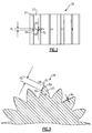
- a plurality of slots 50 are provided at radial locations on a contact face of the gear teeth 27 of the driven gear 26.
- the slots 50 are at or near a center of a width of the gear teeth. While the slots 50 are in the driven gear teeth 27, the invention could also extend to slots formed in the drive gear teeth 25.
- the slots 50 receive fluid from outlet 32 pulsed into the trapped volume to reduce cavitation.
- the slots 50 have a greater width d1 at a tip 51 of the gear teeth 27 than they do at a radially innermost end 52.
- the width d1 at the radial outer portion is more than twice the width d2 at the radial inner portion.
- the width d1 is four times the width at d2.
- the side surfaces 54 of the slots 50 extend toward each other, relative to an axis of rotation of the driven gear 26, such that the shape of a slot 50 is generally a wedge in this plane.
- Figure 3 is a cross-sectional view through a driven gear 26 and shows the slot 50 along another plane.
- the slot 50 is also generally wedge shaped in this plane.
- a depth 56 at the radially outermost location 51 of the slot 50 is much shallower than a depth 58 at the radially innermost end 52.
- the position of the end 52 of the slot 50 is located at gear pitch diameter circumference.
- the depth d4 at the radially innermost end 52 is less than the width d2, and much less than the length d3.
- the depth d4 may be approximately 5 to 10% of the length d3.
- d1 is close to 5 to 10% of a gear width and d2 is equal to half of d1.
- slots 50 As the driven gear 26 rotates, fluid from the outlet port 32 is able to move into the inter-tooth volumes 34 through the slots 50.
- the wedge shape of the slots 50 functions similar to an orifice to channel and force fluid to pressurize into the inter-tooth volumes 34. Cavitation will be reduced.
Landscapes
- Engineering & Computer Science (AREA)
- Mechanical Engineering (AREA)
- General Engineering & Computer Science (AREA)
- Rotary Pumps (AREA)
- Details And Applications Of Rotary Liquid Pumps (AREA)
Claims (6)
- Pompe à engrenages (20) comprenant :un engrenage d'entraînement (24) installé en rotation autour d'un premier axe, ledit engrenage d'entraînement ayant une pluralité de dents d'engrenage (25) au niveau d'un emplacement externe en direction radiale ;un engrenage entraîné (26), ledit engrenage entraîné étant installé en rotation autour d'un second axe, ledit engrenage entraîné comprenant une pluralité de dents (27) au niveau d'un emplacement externe en direction radiale, et lesdites dents de l'engrenage d'entraînement s'engrenant dans lesdites dents de l'engrenage entraîné au niveau des faces de contact correspondantes pour provoquer la rotation dudit engrenage entraîné ; etdes fentes (50) formées dans ladite face de contact d'une parmi lesdites dents de l'engrenage d'entraînement et entraîné,dans laquelle lesdites fentes (50) s'étendent depuis un emplacement externe en direction radiale (51) vers une extrémité radiale la plus interne (52) par rapport à l'axe d'engrenage,et dans laquelle une largeur desdites fentes (50) peut être définie mesurée le long dudit axe d'engrenage,caractérisée en ce que ladite largeur diminue lorsque l'on progresse depuis ledit emplacement externe en direction radiale vers ladite extrémité radiale la plus interne, et en ce que ladite largeur au niveau dudit emplacement externe en direction radiale (51) fait plus du double de ladite largeur au niveau de ladite extrémité radiale la plus interne (52).
- Pompe d'engrenages selon la revendication 1, dans laquelle ladite une parmi lesdites dents de l'engrenage d'entraînement et entraîné est lesdites dents de l'engrenage entraîné (27).
- Pompe d'engrenages selon la revendication 1 ou 2, dans laquelle lesdites fentes s'étendent depuis un bout (51) desdites dents de l'engrenage entraîné en directions radiale et interne.
- Pompe d'engrenages selon la revendication 1, 2 ou 3, dans laquelle une longueur de ladite fente peut être mesurée à une distance entre ledit emplacement externe en direction radiale (51) et ladite extrémité radiale la plus interne (52), et ladite longueur étant supérieure à ladite largeur au niveau dudit emplacement externe en direction radiale.
- Pompe d'engrenages selon la revendication 4, dans laquelle un rapport entre ladite longueur et ladite largeur au niveau dudit emplacement externe en direction radiale (51) est supérieur à 1,5.
- Pompe d'engrenages selon une quelconque revendication précédente, dans laquelle une profondeur de ladite fente (50) peut être définie comme une dimension s'étendant dans ladite face de contact de ladite dent d'engrenage (25,27), et ladite profondeur augmentant depuis ledit emplacement externe en direction radiale (51) vers ladite extrémité radiale la plus interne (52).
Applications Claiming Priority (1)
| Application Number | Priority Date | Filing Date | Title |
|---|---|---|---|
| US12/337,868 US8137085B2 (en) | 2008-12-18 | 2008-12-18 | Gear pump with slots in teeth to reduce cavitation |
Publications (3)
| Publication Number | Publication Date |
|---|---|
| EP2199611A2 EP2199611A2 (fr) | 2010-06-23 |
| EP2199611A3 EP2199611A3 (fr) | 2013-06-05 |
| EP2199611B1 true EP2199611B1 (fr) | 2016-06-22 |
Family
ID=41667717
Family Applications (1)
| Application Number | Title | Priority Date | Filing Date |
|---|---|---|---|
| EP09252832.2A Not-in-force EP2199611B1 (fr) | 2008-12-18 | 2009-12-18 | Pompe à engrenage avec fentes dans la denture pour réduire la cavitation |
Country Status (3)
| Country | Link |
|---|---|
| US (1) | US8137085B2 (fr) |
| EP (1) | EP2199611B1 (fr) |
| JP (1) | JP5078969B2 (fr) |
Families Citing this family (11)
| Publication number | Priority date | Publication date | Assignee | Title |
|---|---|---|---|---|
| US8944793B2 (en) * | 2012-06-05 | 2015-02-03 | Hamilton Sundstrand Corporation | Flow and pressure ripple reduction with advance dual gear and bearing face cut |
| US9068568B2 (en) | 2012-07-23 | 2015-06-30 | Hamilton Sundstrand Corporation | Inlet cutbacks for high speed gear pump |
| US9776728B2 (en) | 2014-07-22 | 2017-10-03 | Hamilton Sundstrand Corporation | Dual-stage gear pump with reduced pressure ripple |
| US9874208B2 (en) | 2015-01-21 | 2018-01-23 | Hamilton Sunstrand Corporation | Bearing faces with fluid channels for gear pumps |
| EP4421323B1 (fr) | 2015-10-30 | 2026-01-28 | Industrial Technologies and Services, LLC | Rotors à vis complexes |
| US10443597B2 (en) | 2016-01-12 | 2019-10-15 | Hamilton Sundstrand Corporation | Gears and gear pumps |
| US10563653B2 (en) | 2016-01-12 | 2020-02-18 | Hamilton Sundstrand Corporation | Gear pump |
| US9945376B2 (en) | 2016-03-16 | 2018-04-17 | Hamilton Sundstrand Corporation | Gear pump |
| IT201800005956A1 (it) * | 2018-06-01 | 2019-12-01 | Macchina volumetrica ad ingranaggi con denti elicoidali | |
| US12486843B2 (en) | 2022-12-19 | 2025-12-02 | Triumph Engine Control Systems, Llc | Volume expansion for cavitation reduction in a gear pump mesh |
| DE102023202577A1 (de) * | 2023-03-22 | 2024-09-26 | Eckerle Technologies GmbH | Zahnrad für eine Zahnradfluidmaschine, Verfahren zum Herstellen eines solchen Zahnrads sowie Zahnradfluidmaschine |
Family Cites Families (25)
| Publication number | Priority date | Publication date | Assignee | Title |
|---|---|---|---|---|
| US1633793A (en) * | 1924-01-25 | 1927-06-28 | Hardinge Brothers Inc | Gear pump |
| US1686867A (en) * | 1926-11-03 | 1928-10-09 | Lewis O Kuhn | Gear pump |
| US1728528A (en) * | 1928-02-21 | 1929-09-17 | Cincinnati Ball Crank Co | Fluid-pressure rotor |
| US2845031A (en) * | 1953-01-13 | 1958-07-29 | Francis W Guibert | Gear tooth construction for rotary fluid meters |
| JPS4427586Y1 (fr) * | 1965-08-17 | 1969-11-17 | ||
| GB1206402A (en) * | 1966-12-07 | 1970-09-23 | Plessey Co Ltd | Improvements in or relating to intermeshing gears in gear pumps |
| GB1467441A (en) * | 1973-03-15 | 1977-03-16 | Lucas Industries Ltd | Hydraulic gear pumps and motors |
| JPS5044909U (fr) * | 1973-08-22 | 1975-05-07 | ||
| DE2421891A1 (de) * | 1974-05-07 | 1975-11-20 | Bosch Gmbh Robert | Zahnradmotor |
| US4233005A (en) * | 1978-01-18 | 1980-11-11 | Lucas Industries Limited | Hydraulic gear pump with recesses in non-working gear flanks |
| US4729727A (en) | 1985-12-23 | 1988-03-08 | Sundstrand Corporation | Gear pump with groove in end wall beginning at outer periphery of pumping chamber and widening toward gear teeth roots |
| JPH0756268B2 (ja) | 1987-07-27 | 1995-06-14 | 株式会社ユニシアジェックス | オイルポンプ |
| JPH02286889A (ja) * | 1989-04-28 | 1990-11-27 | Shimadzu Corp | 歯車ポンプ |
| US5108275A (en) | 1990-12-17 | 1992-04-28 | Sager William F | Rotary pump having helical gear teeth with a small angle of wrap |
| KR940006864B1 (ko) * | 1992-01-16 | 1994-07-28 | 구인회 | 캠기어 펌프장치 |
| EP0754859A3 (fr) * | 1996-06-07 | 1997-12-29 | Maag Pump Systems Textron AG | Roue dentée avec forage |
| US6149415A (en) | 1999-02-11 | 2000-11-21 | Viking Pump, Inc. | Internal gear pump having a feed groove aligned with the roots of the idler teeth |
| US6506037B1 (en) | 1999-11-17 | 2003-01-14 | Carrier Corporation | Screw machine |
| FR2828717A1 (fr) | 2001-08-16 | 2003-02-21 | Michelin Soc Tech | Pompe a engrenage |
| JP2003083260A (ja) * | 2001-09-13 | 2003-03-19 | Koyo Seiko Co Ltd | ギヤポンプ |
| JP2004176633A (ja) * | 2002-11-27 | 2004-06-24 | Toyoda Mach Works Ltd | ギヤポンプ |
| DE10355214A1 (de) * | 2003-11-26 | 2005-06-30 | Robert Bosch Gmbh | Zahnradpumpe, insbesondere Kraftstoffpumpe |
| US7040870B2 (en) | 2003-12-30 | 2006-05-09 | The Goodyear Tire & Rubber Company | Gear pump with gears having curved teeth and method of feeding elastomeric material |
| US7094042B1 (en) | 2004-04-01 | 2006-08-22 | Hamilton Sundstrand Corporation | Dual-inlet gear pump with unequal flow capability |
| FR2888895A3 (fr) * | 2005-07-20 | 2007-01-26 | Renault Sas | Pompe a engrenages |
-
2008
- 2008-12-18 US US12/337,868 patent/US8137085B2/en not_active Expired - Fee Related
-
2009
- 2009-10-29 JP JP2009248361A patent/JP5078969B2/ja not_active Expired - Fee Related
- 2009-12-18 EP EP09252832.2A patent/EP2199611B1/fr not_active Not-in-force
Also Published As
| Publication number | Publication date |
|---|---|
| JP2010144714A (ja) | 2010-07-01 |
| US8137085B2 (en) | 2012-03-20 |
| JP5078969B2 (ja) | 2012-11-21 |
| EP2199611A2 (fr) | 2010-06-23 |
| EP2199611A3 (fr) | 2013-06-05 |
| US20100158739A1 (en) | 2010-06-24 |
Similar Documents
| Publication | Publication Date | Title |
|---|---|---|
| EP2199611B1 (fr) | Pompe à engrenage avec fentes dans la denture pour réduire la cavitation | |
| EP3828415B1 (fr) | Pompe à engrenage interne | |
| US8734140B2 (en) | Reversible gerotor pump | |
| CN105917119B (zh) | 齿轮泵轴承坝 | |
| CN106460851B (zh) | 尤其用于侧通道机器的叶轮 | |
| CA2611761A1 (fr) | Pompe a engrenages a orifice d'admission ameliore | |
| US8087913B2 (en) | Gear pump with unequal gear teeth on drive and driven gear | |
| JP2004084673A (ja) | 圧力流体の事前ローディングを有する外部ギヤポンプ | |
| KR20150094652A (ko) | 기어형 유압 머신 및 상대 기어 휠 | |
| KR101402515B1 (ko) | 브레이크 해제 메커니즘 및 브레이킹 시스템 | |
| US6896500B2 (en) | Gear pump | |
| CN108291537A (zh) | 外啮合齿轮泵 | |
| CN112648183A (zh) | 一种用于子母叶片泵的侧板及双作用子母叶片泵 | |
| US8579618B2 (en) | Internal gear pump with optimized noise behaviour | |
| EP2719861A1 (fr) | Structure de plaque d'équilibrage pour moteur Gerotor | |
| JP2014066244A (ja) | 特に液圧式の車両ブレーキ装置用の内接型ギヤポンプ | |
| CN214304340U (zh) | 一种用于子母叶片泵的侧板及双作用子母叶片泵 | |
| CN214145877U (zh) | 一种伺服节能内转式齿轮泵 | |
| KR100593208B1 (ko) | 회전용적형 펌프의 로터구조 | |
| KR101408674B1 (ko) | 캐비테이션 저감이 가능한 기어 펌프 | |
| JP2014009596A (ja) | ポンプ | |
| EP1970570A2 (fr) | Pompe à engrenages interne | |
| CN107489611B (zh) | 一种小冲击齿轮式油泵 | |
| US20130315756A1 (en) | Oil pump | |
| CN102425543A (zh) | 一种变速箱油泵结构 |
Legal Events
| Date | Code | Title | Description |
|---|---|---|---|
| PUAI | Public reference made under article 153(3) epc to a published international application that has entered the european phase |
Free format text: ORIGINAL CODE: 0009012 |
|
| AK | Designated contracting states |
Kind code of ref document: A2 Designated state(s): AT BE BG CH CY CZ DE DK EE ES FI FR GB GR HR HU IE IS IT LI LT LU LV MC MK MT NL NO PL PT RO SE SI SK SM TR |
|
| AX | Request for extension of the european patent |
Extension state: AL BA RS |
|
| PUAL | Search report despatched |
Free format text: ORIGINAL CODE: 0009013 |
|
| AK | Designated contracting states |
Kind code of ref document: A3 Designated state(s): AT BE BG CH CY CZ DE DK EE ES FI FR GB GR HR HU IE IS IT LI LT LU LV MC MK MT NL NO PL PT RO SE SI SK SM TR |
|
| AX | Request for extension of the european patent |
Extension state: AL BA RS |
|
| RIC1 | Information provided on ipc code assigned before grant |
Ipc: F04C 2/08 20060101AFI20130430BHEP Ipc: F04C 2/14 20060101ALI20130430BHEP |
|
| 17P | Request for examination filed |
Effective date: 20131205 |
|
| RBV | Designated contracting states (corrected) |
Designated state(s): AT BE BG CH CY CZ DE DK EE ES FI FR GB GR HR HU IE IS IT LI LT LU LV MC MK MT NL NO PL PT RO SE SI SK SM TR |
|
| GRAP | Despatch of communication of intention to grant a patent |
Free format text: ORIGINAL CODE: EPIDOSNIGR1 |
|
| RIC1 | Information provided on ipc code assigned before grant |
Ipc: F04C 15/00 20060101ALI20160112BHEP Ipc: F04C 2/18 20060101ALI20160112BHEP Ipc: F04C 2/08 20060101AFI20160112BHEP Ipc: F04C 2/14 20060101ALI20160112BHEP |
|
| INTG | Intention to grant announced |
Effective date: 20160209 |
|
| GRAS | Grant fee paid |
Free format text: ORIGINAL CODE: EPIDOSNIGR3 |
|
| GRAA | (expected) grant |
Free format text: ORIGINAL CODE: 0009210 |
|
| AK | Designated contracting states |
Kind code of ref document: B1 Designated state(s): AT BE BG CH CY CZ DE DK EE ES FI FR GB GR HR HU IE IS IT LI LT LU LV MC MK MT NL NO PL PT RO SE SI SK SM TR |
|
| REG | Reference to a national code |
Ref country code: GB Ref legal event code: FG4D |
|
| REG | Reference to a national code |
Ref country code: CH Ref legal event code: EP |
|
| REG | Reference to a national code |
Ref country code: IE Ref legal event code: FG4D |
|
| REG | Reference to a national code |
Ref country code: AT Ref legal event code: REF Ref document number: 807830 Country of ref document: AT Kind code of ref document: T Effective date: 20160715 |
|
| REG | Reference to a national code |
Ref country code: DE Ref legal event code: R096 Ref document number: 602009039308 Country of ref document: DE |
|
| REG | Reference to a national code |
Ref country code: LT Ref legal event code: MG4D |
|
| REG | Reference to a national code |
Ref country code: NL Ref legal event code: MP Effective date: 20160622 |
|
| PG25 | Lapsed in a contracting state [announced via postgrant information from national office to epo] |
Ref country code: FI Free format text: LAPSE BECAUSE OF FAILURE TO SUBMIT A TRANSLATION OF THE DESCRIPTION OR TO PAY THE FEE WITHIN THE PRESCRIBED TIME-LIMIT Effective date: 20160622 Ref country code: LT Free format text: LAPSE BECAUSE OF FAILURE TO SUBMIT A TRANSLATION OF THE DESCRIPTION OR TO PAY THE FEE WITHIN THE PRESCRIBED TIME-LIMIT Effective date: 20160622 Ref country code: NO Free format text: LAPSE BECAUSE OF FAILURE TO SUBMIT A TRANSLATION OF THE DESCRIPTION OR TO PAY THE FEE WITHIN THE PRESCRIBED TIME-LIMIT Effective date: 20160922 |
|
| REG | Reference to a national code |
Ref country code: AT Ref legal event code: MK05 Ref document number: 807830 Country of ref document: AT Kind code of ref document: T Effective date: 20160622 |
|
| PG25 | Lapsed in a contracting state [announced via postgrant information from national office to epo] |
Ref country code: LV Free format text: LAPSE BECAUSE OF FAILURE TO SUBMIT A TRANSLATION OF THE DESCRIPTION OR TO PAY THE FEE WITHIN THE PRESCRIBED TIME-LIMIT Effective date: 20160622 Ref country code: GR Free format text: LAPSE BECAUSE OF FAILURE TO SUBMIT A TRANSLATION OF THE DESCRIPTION OR TO PAY THE FEE WITHIN THE PRESCRIBED TIME-LIMIT Effective date: 20160923 Ref country code: SE Free format text: LAPSE BECAUSE OF FAILURE TO SUBMIT A TRANSLATION OF THE DESCRIPTION OR TO PAY THE FEE WITHIN THE PRESCRIBED TIME-LIMIT Effective date: 20160622 Ref country code: HR Free format text: LAPSE BECAUSE OF FAILURE TO SUBMIT A TRANSLATION OF THE DESCRIPTION OR TO PAY THE FEE WITHIN THE PRESCRIBED TIME-LIMIT Effective date: 20160622 Ref country code: NL Free format text: LAPSE BECAUSE OF FAILURE TO SUBMIT A TRANSLATION OF THE DESCRIPTION OR TO PAY THE FEE WITHIN THE PRESCRIBED TIME-LIMIT Effective date: 20160622 |
|
| PG25 | Lapsed in a contracting state [announced via postgrant information from national office to epo] |
Ref country code: EE Free format text: LAPSE BECAUSE OF FAILURE TO SUBMIT A TRANSLATION OF THE DESCRIPTION OR TO PAY THE FEE WITHIN THE PRESCRIBED TIME-LIMIT Effective date: 20160622 Ref country code: IS Free format text: LAPSE BECAUSE OF FAILURE TO SUBMIT A TRANSLATION OF THE DESCRIPTION OR TO PAY THE FEE WITHIN THE PRESCRIBED TIME-LIMIT Effective date: 20161022 Ref country code: SK Free format text: LAPSE BECAUSE OF FAILURE TO SUBMIT A TRANSLATION OF THE DESCRIPTION OR TO PAY THE FEE WITHIN THE PRESCRIBED TIME-LIMIT Effective date: 20160622 Ref country code: IT Free format text: LAPSE BECAUSE OF FAILURE TO SUBMIT A TRANSLATION OF THE DESCRIPTION OR TO PAY THE FEE WITHIN THE PRESCRIBED TIME-LIMIT Effective date: 20160622 Ref country code: RO Free format text: LAPSE BECAUSE OF FAILURE TO SUBMIT A TRANSLATION OF THE DESCRIPTION OR TO PAY THE FEE WITHIN THE PRESCRIBED TIME-LIMIT Effective date: 20160622 Ref country code: CZ Free format text: LAPSE BECAUSE OF FAILURE TO SUBMIT A TRANSLATION OF THE DESCRIPTION OR TO PAY THE FEE WITHIN THE PRESCRIBED TIME-LIMIT Effective date: 20160622 |
|
| PG25 | Lapsed in a contracting state [announced via postgrant information from national office to epo] |
Ref country code: AT Free format text: LAPSE BECAUSE OF FAILURE TO SUBMIT A TRANSLATION OF THE DESCRIPTION OR TO PAY THE FEE WITHIN THE PRESCRIBED TIME-LIMIT Effective date: 20160622 Ref country code: ES Free format text: LAPSE BECAUSE OF FAILURE TO SUBMIT A TRANSLATION OF THE DESCRIPTION OR TO PAY THE FEE WITHIN THE PRESCRIBED TIME-LIMIT Effective date: 20160622 Ref country code: BE Free format text: LAPSE BECAUSE OF FAILURE TO SUBMIT A TRANSLATION OF THE DESCRIPTION OR TO PAY THE FEE WITHIN THE PRESCRIBED TIME-LIMIT Effective date: 20160622 Ref country code: PL Free format text: LAPSE BECAUSE OF FAILURE TO SUBMIT A TRANSLATION OF THE DESCRIPTION OR TO PAY THE FEE WITHIN THE PRESCRIBED TIME-LIMIT Effective date: 20160622 Ref country code: SM Free format text: LAPSE BECAUSE OF FAILURE TO SUBMIT A TRANSLATION OF THE DESCRIPTION OR TO PAY THE FEE WITHIN THE PRESCRIBED TIME-LIMIT Effective date: 20160622 Ref country code: PT Free format text: LAPSE BECAUSE OF FAILURE TO SUBMIT A TRANSLATION OF THE DESCRIPTION OR TO PAY THE FEE WITHIN THE PRESCRIBED TIME-LIMIT Effective date: 20161024 |
|
| REG | Reference to a national code |
Ref country code: DE Ref legal event code: R097 Ref document number: 602009039308 Country of ref document: DE |
|
| PLBE | No opposition filed within time limit |
Free format text: ORIGINAL CODE: 0009261 |
|
| STAA | Information on the status of an ep patent application or granted ep patent |
Free format text: STATUS: NO OPPOSITION FILED WITHIN TIME LIMIT |
|
| 26N | No opposition filed |
Effective date: 20170323 |
|
| PG25 | Lapsed in a contracting state [announced via postgrant information from national office to epo] |
Ref country code: DK Free format text: LAPSE BECAUSE OF FAILURE TO SUBMIT A TRANSLATION OF THE DESCRIPTION OR TO PAY THE FEE WITHIN THE PRESCRIBED TIME-LIMIT Effective date: 20160622 |
|
| REG | Reference to a national code |
Ref country code: CH Ref legal event code: PL |
|
| PG25 | Lapsed in a contracting state [announced via postgrant information from national office to epo] |
Ref country code: SI Free format text: LAPSE BECAUSE OF FAILURE TO SUBMIT A TRANSLATION OF THE DESCRIPTION OR TO PAY THE FEE WITHIN THE PRESCRIBED TIME-LIMIT Effective date: 20160622 |
|
| PG25 | Lapsed in a contracting state [announced via postgrant information from national office to epo] |
Ref country code: MC Free format text: LAPSE BECAUSE OF FAILURE TO SUBMIT A TRANSLATION OF THE DESCRIPTION OR TO PAY THE FEE WITHIN THE PRESCRIBED TIME-LIMIT Effective date: 20160622 |
|
| REG | Reference to a national code |
Ref country code: FR Ref legal event code: ST Effective date: 20170831 |
|
| REG | Reference to a national code |
Ref country code: IE Ref legal event code: MM4A |
|
| PG25 | Lapsed in a contracting state [announced via postgrant information from national office to epo] |
Ref country code: CH Free format text: LAPSE BECAUSE OF NON-PAYMENT OF DUE FEES Effective date: 20161231 Ref country code: LI Free format text: LAPSE BECAUSE OF NON-PAYMENT OF DUE FEES Effective date: 20161231 Ref country code: FR Free format text: LAPSE BECAUSE OF NON-PAYMENT OF DUE FEES Effective date: 20170102 Ref country code: LU Free format text: LAPSE BECAUSE OF NON-PAYMENT OF DUE FEES Effective date: 20161218 |
|
| PG25 | Lapsed in a contracting state [announced via postgrant information from national office to epo] |
Ref country code: IE Free format text: LAPSE BECAUSE OF NON-PAYMENT OF DUE FEES Effective date: 20161218 |
|
| PG25 | Lapsed in a contracting state [announced via postgrant information from national office to epo] |
Ref country code: HU Free format text: LAPSE BECAUSE OF FAILURE TO SUBMIT A TRANSLATION OF THE DESCRIPTION OR TO PAY THE FEE WITHIN THE PRESCRIBED TIME-LIMIT; INVALID AB INITIO Effective date: 20091218 Ref country code: CY Free format text: LAPSE BECAUSE OF FAILURE TO SUBMIT A TRANSLATION OF THE DESCRIPTION OR TO PAY THE FEE WITHIN THE PRESCRIBED TIME-LIMIT Effective date: 20160622 |
|
| PG25 | Lapsed in a contracting state [announced via postgrant information from national office to epo] |
Ref country code: TR Free format text: LAPSE BECAUSE OF FAILURE TO SUBMIT A TRANSLATION OF THE DESCRIPTION OR TO PAY THE FEE WITHIN THE PRESCRIBED TIME-LIMIT Effective date: 20160622 Ref country code: MK Free format text: LAPSE BECAUSE OF FAILURE TO SUBMIT A TRANSLATION OF THE DESCRIPTION OR TO PAY THE FEE WITHIN THE PRESCRIBED TIME-LIMIT Effective date: 20160622 |
|
| PG25 | Lapsed in a contracting state [announced via postgrant information from national office to epo] |
Ref country code: BG Free format text: LAPSE BECAUSE OF FAILURE TO SUBMIT A TRANSLATION OF THE DESCRIPTION OR TO PAY THE FEE WITHIN THE PRESCRIBED TIME-LIMIT Effective date: 20160622 |
|
| PG25 | Lapsed in a contracting state [announced via postgrant information from national office to epo] |
Ref country code: MT Free format text: LAPSE BECAUSE OF NON-PAYMENT OF DUE FEES Effective date: 20161218 |
|
| REG | Reference to a national code |
Ref country code: DE Ref legal event code: R082 Ref document number: 602009039308 Country of ref document: DE |
|
| PGFP | Annual fee paid to national office [announced via postgrant information from national office to epo] |
Ref country code: GB Payment date: 20211118 Year of fee payment: 13 Ref country code: DE Payment date: 20211117 Year of fee payment: 13 |
|
| REG | Reference to a national code |
Ref country code: DE Ref legal event code: R119 Ref document number: 602009039308 Country of ref document: DE |
|
| GBPC | Gb: european patent ceased through non-payment of renewal fee |
Effective date: 20221218 |
|
| PG25 | Lapsed in a contracting state [announced via postgrant information from national office to epo] |
Ref country code: GB Free format text: LAPSE BECAUSE OF NON-PAYMENT OF DUE FEES Effective date: 20221218 Ref country code: DE Free format text: LAPSE BECAUSE OF NON-PAYMENT OF DUE FEES Effective date: 20230701 |