EP2199625A1 - Cheville adhésive - Google Patents
Cheville adhésive Download PDFInfo
- Publication number
- EP2199625A1 EP2199625A1 EP09179413A EP09179413A EP2199625A1 EP 2199625 A1 EP2199625 A1 EP 2199625A1 EP 09179413 A EP09179413 A EP 09179413A EP 09179413 A EP09179413 A EP 09179413A EP 2199625 A1 EP2199625 A1 EP 2199625A1
- Authority
- EP
- European Patent Office
- Prior art keywords
- adhesive
- head
- webs
- shaft
- axially
- Prior art date
- Legal status (The legal status is an assumption and is not a legal conclusion. Google has not performed a legal analysis and makes no representation as to the accuracy of the status listed.)
- Granted
Links
- 239000000853 adhesive Substances 0.000 title claims abstract description 111
- 230000001070 adhesive effect Effects 0.000 title claims abstract description 111
- 238000009826 distribution Methods 0.000 claims description 7
- 238000009434 installation Methods 0.000 claims description 4
- 239000006261 foam material Substances 0.000 claims description 3
- 238000003780 insertion Methods 0.000 claims description 3
- 230000037431 insertion Effects 0.000 claims description 3
- 239000002390 adhesive tape Substances 0.000 claims description 2
- 230000002093 peripheral effect Effects 0.000 claims description 2
- 238000010276 construction Methods 0.000 claims 1
- 239000003292 glue Substances 0.000 claims 1
- 230000003139 buffering effect Effects 0.000 abstract 2
- 229920005830 Polyurethane Foam Polymers 0.000 description 4
- 230000000694 effects Effects 0.000 description 3
- 238000000034 method Methods 0.000 description 3
- 241000209035 Ilex Species 0.000 description 2
- 230000004308 accommodation Effects 0.000 description 2
- 239000006260 foam Substances 0.000 description 2
- 230000009931 harmful effect Effects 0.000 description 2
- 239000000463 material Substances 0.000 description 2
- 239000000126 substance Substances 0.000 description 2
- 241000771208 Buchanania arborescens Species 0.000 description 1
- 244000025254 Cannabis sativa Species 0.000 description 1
- 235000012766 Cannabis sativa ssp. sativa var. sativa Nutrition 0.000 description 1
- 235000012765 Cannabis sativa ssp. sativa var. spontanea Nutrition 0.000 description 1
- 240000007182 Ochroma pyramidale Species 0.000 description 1
- 230000004323 axial length Effects 0.000 description 1
- 235000009120 camo Nutrition 0.000 description 1
- 239000004568 cement Substances 0.000 description 1
- 235000005607 chanvre indien Nutrition 0.000 description 1
- 239000011093 chipboard Substances 0.000 description 1
- 239000002131 composite material Substances 0.000 description 1
- 238000005553 drilling Methods 0.000 description 1
- 239000000835 fiber Substances 0.000 description 1
- 239000002657 fibrous material Substances 0.000 description 1
- 230000006870 function Effects 0.000 description 1
- 239000011487 hemp Substances 0.000 description 1
- 238000002347 injection Methods 0.000 description 1
- 239000007924 injection Substances 0.000 description 1
- 238000011089 mechanical engineering Methods 0.000 description 1
- 238000005457 optimization Methods 0.000 description 1
- 230000000704 physical effect Effects 0.000 description 1
- 238000003892 spreading Methods 0.000 description 1
- 239000010902 straw Substances 0.000 description 1
- 238000005728 strengthening Methods 0.000 description 1
Images


Classifications
-
- F—MECHANICAL ENGINEERING; LIGHTING; HEATING; WEAPONS; BLASTING
- F16—ENGINEERING ELEMENTS AND UNITS; GENERAL MEASURES FOR PRODUCING AND MAINTAINING EFFECTIVE FUNCTIONING OF MACHINES OR INSTALLATIONS; THERMAL INSULATION IN GENERAL
- F16B—DEVICES FOR FASTENING OR SECURING CONSTRUCTIONAL ELEMENTS OR MACHINE PARTS TOGETHER, e.g. NAILS, BOLTS, CIRCLIPS, CLAMPS, CLIPS OR WEDGES; JOINTS OR JOINTING
- F16B5/00—Joining sheets or plates, e.g. panels, to one another or to strips or bars parallel to them
- F16B5/01—Joining sheets or plates, e.g. panels, to one another or to strips or bars parallel to them by means of fastening elements specially adapted for honeycomb panels
-
- F—MECHANICAL ENGINEERING; LIGHTING; HEATING; WEAPONS; BLASTING
- F16—ENGINEERING ELEMENTS AND UNITS; GENERAL MEASURES FOR PRODUCING AND MAINTAINING EFFECTIVE FUNCTIONING OF MACHINES OR INSTALLATIONS; THERMAL INSULATION IN GENERAL
- F16B—DEVICES FOR FASTENING OR SECURING CONSTRUCTIONAL ELEMENTS OR MACHINE PARTS TOGETHER, e.g. NAILS, BOLTS, CIRCLIPS, CLAMPS, CLIPS OR WEDGES; JOINTS OR JOINTING
- F16B13/00—Dowels or other devices fastened in walls or the like by inserting them in holes made therein for that purpose
- F16B13/14—Non-metallic plugs or sleeves; Use of liquid, loose solid or kneadable material therefor
- F16B13/141—Fixing plugs in holes by the use of settable material
Definitions
- the invention relates to an adhesive bucket according to the preamble of claim 1.
- Adhesive dowels or injection dowels for use on lightweight panels, which have a central position, are known per se, so from the WO 2006/106131 A1 , This type of adhesive bucket are particularly suitable for use in lightweight panels with a central layer of cardboard honeycomb structures. Such honeycomb structures are characterized in that they have relatively large air chambers.
- Be dowels of the generic WO 2006/106131 A1 However, applied in lightweight panels with a middle layer of PU foam or similar materials with very small air chambers, the dosage of the adhesive is difficult, because excess adhesive does not dodge and therefore is pressed uncontrollably at the slightest excess from the dowel.
- the invention has the object to solve this problem.
- the embodiment is such that adhesive, which can be supplied through the adhesive supply channel, is initially distributed simultaneously or successively at the two axial ends of the shank into receiving spaces A and B by means of a channel and / or the web structure, before, in the case of further feeding of adhesive flows over this in an axially formed between the receiving spaces adhesive buffer space.
- the adhesive is guided in correspondingly shaped channels selectively first to the one cover layer and then to the other cover layer, so that a good connection of the anchor with the cover layers and thus a high strength is ensured.
- the invention also provides a lightweight board with a bonding plug according to any one of the preceding claims, preferably with an intermediate layer of a relatively fine-pored foam material.
- one or the middle layer of the lightweight structural panels deviates in their chemical and / or physical properties from the at least two outer layers.
- middle layers are known, which consist of light woods such as balsa. Another possibility is to build up the middle layer from fiber materials such as hemp or straw fibers.
- the middle layer cavities such as extruded tubular chipboard or honeycomb panels can be produced.
- the density between middle layer and top layers can be varied to obtain a lightweight board.
- the middle layer can be carried out the middle layer as a foam, such as foam core plates.
- this method is suitable for any lightweight panels constructed according to the above-described concept.
- the cover plates of the lightweight panels are preferred designed to withstand tensile and compressive loads, the middle layer holds preferred pressure loads.
- a further consideration can be made from the point of view of a double-T carrier as it is known from mechanical engineering. According to this consideration, the middle layer of a lightweight board has less effect on the moment of resistance of the lightweight board than the cover plates.
- FIGS. 1d and e show the arrangements of a lightweight board 1 with the cover layers 2, 3. Between the cover layers 2, 3 is an outer layers connecting the cover layers 2, 3 intermediate layer (dashed lines in the corners of the lightweight panel 1 indicated) formed, in particular from a relatively fine-pored foam material can exist. This material situation is in Fig. 1 the better recognizability of the installation position otherwise not shown.
- the adhesive bucket 4 is formed as an elongated, preferably cylindrical element, which is such Length that it bridges the distance between the cover layers 2, 3 in the assembled state.
- the adhesive bucket 4 has a cylindrical head 5, on which a shaft region 6 connects.
- the head 5 is designed to engage in a corresponding bore 7 in the cover layer 2 of the lightweight panel 1.
- the shaft 6 is in this installation position of Fig. 1c and d between the cover layers 2, 3 and extends in an aligned with the bore 7 opening in the intermediate layer.
- the shank 6 is preferably dimensioned such that it extends directly to the surface of the cover layer 3 facing away from the head 5 in the installation position.
- the head 5 is preferably formed profiled on its peripheral surface in order to ensure a good fit in the bore 7.
- the adhesive plug 4 is provided with an adhesive supply channel 8, which passes through the head 5 and the shaft 6 axially. According to a preferred embodiment, the Klebbstoffzu Georgiakanal 8 passes through the adhesive plug 4 over its entire axial length.
- the shaft 6 has a diameter which is smaller than the diameter of the head 5.
- the Klebstoffzu Foodkanal 8 At its end facing away from the head 5, the Klebstoffzu Canalkanal 8 has a circumferential wall of the shaft radially passing through opening 9.
- a web structure 10 is formed, which has channels for distributing the adhesive.
- the web structure 10 is designed such that adhesive, which is supplied through the Klebstoffzu Technologykanal 8, by means of the web structure 10 is first passed to the axial ends of the shaft 6, where it is in each case in the receiving spaces A and B can distribute before, in the case of further supply of adhesive, this is passed into an adhesive buffer space C formed between the axial ends of the shaft.
- the web structure 10 is formed such that the adhesive, which is fed through the Klebstoffzu Technologykanal 8, by means of the web structure 10 is first passed to the end remote from the head 5 end of the shaft 6 in the receiving space A and from there further through the web structure 10th to the other axial end in front of the head 5 in the receiving space B and from the receiving space B in the buffer space C.
- the web structure 10 has a geometry such that adhesive emerging from the opening 9 is conducted to the interior regions of the lightweight building board adjoining the two cover layers 2, 3, such that the adhesive bucket in the hardened state of the adhesive in these Receiving spaces A and B is securely anchored in the lightweight panel, so that through its head 5 a fastener, such as a screw can be introduced into the shaft 6.
- the web structure 10 has at least two ring webs 11, 12 which are not circumferentially closed around the outer circumference and are axially spaced from one another.
- the opening 9 is seen from the head 5 from behind the two annular webs 11, 12 is formed.
- These ring webs 11, 12 are further spaced apart from the one cover layer 2 with the head 5 and the other opposite cover layer 3 in the installed position, so that in each case between the annular web 12 and the head 5 and a cover layer 2 on one side of the lightweight board 1 and between the other ring land 11 and the other cover layer 3 on the other side of the lightweight board 1, the adhesive receiving spaces A and B are formed.
- One of the connecting webs 14 a connects the two annular webs 11, 12 axially with each other and ends at these annular webs 11, 12th
- the other of the two connecting webs 14b of the embodiment of Fig. 1 on the other hand extends beyond the annular webs 11, 12, preferably on the one hand to the head 5 and on the other hand to the end of the shaft 6 facing away from the head 5,
- the opening 9 from the shaft 6 in the annular space 14 at the end remote from the head 5 of the adhesive plug 4 is preferably on the of the connecting channel 13 opposite side of the longer connecting web 14 b formed.
- annular web 12 which is closer to the head 5, does not extend all the way around the outer circumference 8 as far as this longer connecting web 14b, so that a gap 15 is formed through which adhesive from the adhesive receiving space B into the region 16 between the annular webs 11 and 12 which serves as the buffer space C for the adhesive.
- an adhesive distribution structure is formed in the adhesive bucket, with which adhesive is first passed through the head 5 and the shaft 6 through the Klebbstoffzu thoroughlykanal 8 to the opening 9, through the opening 9 (in web structure 10) in the adhesive receiving space A, from there into the adhesive receiving space B and from there, if even further - so in itself too much - adhesive is supplied, in the buffer space C (arrow P).
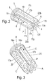
- FIG. 2 To Fig. 2 are circumferentially distributed several - exemplified eight - connecting webs 17 a, b, c, ... provided. These connecting webs 17 extend axially beyond the end of the shaft 6, which correspondingly ends in the installed position somewhat further from the cover layer 3.
- the Klebstoffzu 2008kanal 8 opens between the axially above the end of the shaft 6 protruding ends of the connecting webs 17a, ... formed receiving space A for adhesive, which is bounded axially by some circumferentially distributed on the outer circumference of the shaft 6 arranged ring segment webs 23a, b, ...
- At least one or more axial connection channels 18 are formed between the adjacent connecting webs 17a, b, without ring segment webs 23a, b.
- adhesive flows first into the receiving space A and then through the one or more connecting channels 18a, b, ... to the end of the shaft 6 at the head 5, where a further adhesive receiving space B is formed.
- Fig. 3 corresponds to the Fig. 2 except for the feature that in each case both connecting webs 17a, b, which adjoin the respective axially extending distribution channel 18a, b, ..., do not extend all the way to the head 5, so that two columns 19, the gaps 19a, b , ..., through which adhesive can pass, so that on the one hand, the adhesive receiving space B at the head 5 forms and on the other hand, a deflection in axial channels 20, which form the buffer space C for adhesive.
- FIGS. 2 and 3 each preferably more of these structures of connecting webs 17 and distribution channels 18 and columns and axial channels 20 distributed on the circumference of the shaft 6.
- the adhesive flows (arrow P) first again only by the shaft 6 in the receiving space A at the end facing away from the head 5 end of the shaft 6, then through the web structure 10 to the receiving space B at the head 5 and from there into the buffer space C.
- the adhesive pressed into this buffer space C has no or at least no appreciable strengthening effect (the bonding with the middle layer, for example, made of PU foam usually does not increase the strength), it also has no harmful effect.
- the function of an outer sleeve takes over in a lightweight board with a sufficiently dense middle layer, for example in a PU foam board as the middle layer, the middle layer itself. Accordingly, in the embodiments of Fig. 1 to 3 no outer, the shank 6 and the web structure 10 surrounding sleeve provided.
- the adhesive bucket 4 can also be used on plates or walls, which are not designed as lightweight panels of the type described.
- the actual inner adhesive bucket can be provided with an outer sleeve, which after Fig. 4 as a prefabricated sleeve member 21 and after Fig. 5 is formed by a jacket 22 made of adhesive tape, wherein the sleeve covers only the axial region of the buffer space C, but preferably not the receiving spaces A and B, axially.
- the inner feed channel also does not lead to the head, but can open into a reservoir area in the interior of the adhesive plug, in which factory already adhesive is pre-filled. After insertion into the lightweight board this area is opened (eg by axial pressure through an opening in the head, so that, for example, a thin wall is broken, so that the adhesive as described above escape outwardly from the shaft into the web structure 10 and in Area of the web structure 10 can spread or distribute.
Landscapes
- Engineering & Computer Science (AREA)
- General Engineering & Computer Science (AREA)
- Mechanical Engineering (AREA)
- Joining Of Building Structures In Genera (AREA)
- Standing Axle, Rod, Or Tube Structures Coupled By Welding, Adhesion, Or Deposition (AREA)
Applications Claiming Priority (2)
| Application Number | Priority Date | Filing Date | Title |
|---|---|---|---|
| DE202008016855 | 2008-12-22 | ||
| DE202009002923U DE202009002923U1 (de) | 2008-12-22 | 2009-03-04 | Klebedübel |
Publications (2)
| Publication Number | Publication Date |
|---|---|
| EP2199625A1 true EP2199625A1 (fr) | 2010-06-23 |
| EP2199625B1 EP2199625B1 (fr) | 2012-09-12 |
Family
ID=41728350
Family Applications (1)
| Application Number | Title | Priority Date | Filing Date |
|---|---|---|---|
| EP20090179413 Not-in-force EP2199625B1 (fr) | 2008-12-22 | 2009-12-16 | Cheville adhésive |
Country Status (2)
| Country | Link |
|---|---|
| EP (1) | EP2199625B1 (fr) |
| DE (1) | DE202009002923U1 (fr) |
Families Citing this family (1)
| Publication number | Priority date | Publication date | Assignee | Title |
|---|---|---|---|---|
| DE102016204662A1 (de) * | 2016-03-22 | 2017-09-28 | Bayerische Motoren Werke Aktiengesellschaft | Schraubverbindung |
Citations (3)
| Publication number | Priority date | Publication date | Assignee | Title |
|---|---|---|---|---|
| EP0651100A2 (fr) * | 1993-10-30 | 1995-05-03 | HOME Co., Ltd. | Connecteur |
| DE202008001093U1 (de) * | 2008-01-25 | 2009-06-18 | Hettich-Heinze Gmbh & Co. Kg | Verbindungselement |
| DE102008024321A1 (de) * | 2008-05-20 | 2009-11-26 | Fischerwerke Gmbh & Co. Kg | Befestigungshülse |
Family Cites Families (1)
| Publication number | Priority date | Publication date | Assignee | Title |
|---|---|---|---|---|
| DE202005005579U1 (de) | 2005-04-07 | 2006-08-17 | Hettich-Heinze Gmbh & Co. Kg | Verbindungseinsatz |
-
2009
- 2009-03-04 DE DE202009002923U patent/DE202009002923U1/de not_active Expired - Lifetime
- 2009-12-16 EP EP20090179413 patent/EP2199625B1/fr not_active Not-in-force
Patent Citations (3)
| Publication number | Priority date | Publication date | Assignee | Title |
|---|---|---|---|---|
| EP0651100A2 (fr) * | 1993-10-30 | 1995-05-03 | HOME Co., Ltd. | Connecteur |
| DE202008001093U1 (de) * | 2008-01-25 | 2009-06-18 | Hettich-Heinze Gmbh & Co. Kg | Verbindungselement |
| DE102008024321A1 (de) * | 2008-05-20 | 2009-11-26 | Fischerwerke Gmbh & Co. Kg | Befestigungshülse |
Also Published As
| Publication number | Publication date |
|---|---|
| DE202009002923U1 (de) | 2010-05-20 |
| EP2199625B1 (fr) | 2012-09-12 |
Similar Documents
| Publication | Publication Date | Title |
|---|---|---|
| DE10035580B4 (de) | Formschlüssig setzbarer Hinterschneid-Anker | |
| DE102007051628B4 (de) | Teleskopdübel II und Setzverfahren | |
| EP3365565B1 (fr) | Procede d'application d'une cheville extensible sur un substrat, une masse durcissable etant inseree dans l'espace annulaire autour de la cheville extensible | |
| EP2158406A2 (fr) | Ferrure de fixation pour un panneau léger | |
| EP2191151A2 (fr) | Cheville pour la prise par l'arrière automatique dans un panneau de couverture et procédé de collage par injection de la cheville | |
| EP3057774B1 (fr) | Pièce munie d'une partie fixation permettant un assemblage par vis et pièce moulée et élément de fixation | |
| DE2556493A1 (de) | Verankerungsbolzen | |
| DE102006053141B3 (de) | Verbesserter Gleitanker | |
| EP2350472A1 (fr) | Goujon collé | |
| EP0472851A2 (fr) | Cheville expansible | |
| EP2199625B1 (fr) | Cheville adhésive | |
| DE3733621A1 (de) | Duebel aus kunststoff | |
| EP3279485A1 (fr) | Cheville d'isolation a revetement partiel | |
| EP1179649B1 (fr) | Ancrage de fixation par injection | |
| EP4459073A1 (fr) | Renforcement pour un support de béton poreux, support de béton poreux, utilisation d'un support de béton poreux, procédé de renforcement d'un support de béton poreux et utilisation d'un renforcement | |
| DE4403894A1 (de) | Spreizdübel | |
| EP0697530B1 (fr) | Boulon d'ancrage pour béton ou similaire | |
| EP4524406B1 (fr) | Cheville adhésive pour un panneau léger, panneau léger et procédé de montage d'une cheville adhésive dans un panneau léger | |
| DE102018108402B4 (de) | Verbindungssteckteil für einen Felgenring, insbesondere für Fahrräder | |
| EP3301313B1 (fr) | Ancre adhésif | |
| DE102017126056A1 (de) | Verfahren zum Befestigen eines Dämmstoffelements und Dämmstoffdübel | |
| EP2634439B1 (fr) | Douille perforée pour une cheville | |
| DE29803927U1 (de) | Vorrichtung zur Erstellung eines Verbundankers in hohlen Bauteilen | |
| DE202010008496U1 (de) | Schalungs-Abstandhalter und Schalung | |
| EP1705301B1 (fr) | Tuyau d'injection ou pression et procédé d'étanchéification de joints entre éléments de construction |
Legal Events
| Date | Code | Title | Description |
|---|---|---|---|
| PUAI | Public reference made under article 153(3) epc to a published international application that has entered the european phase |
Free format text: ORIGINAL CODE: 0009012 |
|
| AK | Designated contracting states |
Kind code of ref document: A1 Designated state(s): AT BE BG CH CY CZ DE DK EE ES FI FR GB GR HR HU IE IS IT LI LT LU LV MC MK MT NL NO PL PT RO SE SI SK SM TR |
|
| AX | Request for extension of the european patent |
Extension state: AL BA RS |
|
| 17P | Request for examination filed |
Effective date: 20101222 |
|
| GRAP | Despatch of communication of intention to grant a patent |
Free format text: ORIGINAL CODE: EPIDOSNIGR1 |
|
| RIN1 | Information on inventor provided before grant (corrected) |
Inventor name: ANDSCHUS, STEFAN Inventor name: SOBOLEWSKI, UWE |
|
| GRAS | Grant fee paid |
Free format text: ORIGINAL CODE: EPIDOSNIGR3 |
|
| GRAA | (expected) grant |
Free format text: ORIGINAL CODE: 0009210 |
|
| AK | Designated contracting states |
Kind code of ref document: B1 Designated state(s): AT BE BG CH CY CZ DE DK EE ES FI FR GB GR HR HU IE IS IT LI LT LU LV MC MK MT NL NO PL PT RO SE SI SK SM TR |
|
| REG | Reference to a national code |
Ref country code: GB Ref legal event code: FG4D Free format text: NOT ENGLISH |
|
| REG | Reference to a national code |
Ref country code: CH Ref legal event code: EP |
|
| REG | Reference to a national code |
Ref country code: AT Ref legal event code: REF Ref document number: 575233 Country of ref document: AT Kind code of ref document: T Effective date: 20120915 |
|
| REG | Reference to a national code |
Ref country code: IE Ref legal event code: FG4D Free format text: LANGUAGE OF EP DOCUMENT: GERMAN |
|
| REG | Reference to a national code |
Ref country code: DE Ref legal event code: R096 Ref document number: 502009004720 Country of ref document: DE Effective date: 20121108 |
|
| PG25 | Lapsed in a contracting state [announced via postgrant information from national office to epo] |
Ref country code: FI Free format text: LAPSE BECAUSE OF FAILURE TO SUBMIT A TRANSLATION OF THE DESCRIPTION OR TO PAY THE FEE WITHIN THE PRESCRIBED TIME-LIMIT Effective date: 20120912 Ref country code: NO Free format text: LAPSE BECAUSE OF FAILURE TO SUBMIT A TRANSLATION OF THE DESCRIPTION OR TO PAY THE FEE WITHIN THE PRESCRIBED TIME-LIMIT Effective date: 20121212 Ref country code: HR Free format text: LAPSE BECAUSE OF FAILURE TO SUBMIT A TRANSLATION OF THE DESCRIPTION OR TO PAY THE FEE WITHIN THE PRESCRIBED TIME-LIMIT Effective date: 20120912 Ref country code: LT Free format text: LAPSE BECAUSE OF FAILURE TO SUBMIT A TRANSLATION OF THE DESCRIPTION OR TO PAY THE FEE WITHIN THE PRESCRIBED TIME-LIMIT Effective date: 20120912 Ref country code: CY Free format text: LAPSE BECAUSE OF FAILURE TO SUBMIT A TRANSLATION OF THE DESCRIPTION OR TO PAY THE FEE WITHIN THE PRESCRIBED TIME-LIMIT Effective date: 20120912 |
|
| REG | Reference to a national code |
Ref country code: NL Ref legal event code: VDEP Effective date: 20120912 |
|
| REG | Reference to a national code |
Ref country code: LT Ref legal event code: MG4D Effective date: 20120912 |
|
| PG25 | Lapsed in a contracting state [announced via postgrant information from national office to epo] |
Ref country code: SI Free format text: LAPSE BECAUSE OF FAILURE TO SUBMIT A TRANSLATION OF THE DESCRIPTION OR TO PAY THE FEE WITHIN THE PRESCRIBED TIME-LIMIT Effective date: 20120912 Ref country code: SE Free format text: LAPSE BECAUSE OF FAILURE TO SUBMIT A TRANSLATION OF THE DESCRIPTION OR TO PAY THE FEE WITHIN THE PRESCRIBED TIME-LIMIT Effective date: 20120912 Ref country code: GR Free format text: LAPSE BECAUSE OF FAILURE TO SUBMIT A TRANSLATION OF THE DESCRIPTION OR TO PAY THE FEE WITHIN THE PRESCRIBED TIME-LIMIT Effective date: 20121213 Ref country code: LV Free format text: LAPSE BECAUSE OF FAILURE TO SUBMIT A TRANSLATION OF THE DESCRIPTION OR TO PAY THE FEE WITHIN THE PRESCRIBED TIME-LIMIT Effective date: 20120912 |
|
| PG25 | Lapsed in a contracting state [announced via postgrant information from national office to epo] |
Ref country code: NL Free format text: LAPSE BECAUSE OF FAILURE TO SUBMIT A TRANSLATION OF THE DESCRIPTION OR TO PAY THE FEE WITHIN THE PRESCRIBED TIME-LIMIT Effective date: 20120912 Ref country code: ES Free format text: LAPSE BECAUSE OF FAILURE TO SUBMIT A TRANSLATION OF THE DESCRIPTION OR TO PAY THE FEE WITHIN THE PRESCRIBED TIME-LIMIT Effective date: 20121223 Ref country code: IS Free format text: LAPSE BECAUSE OF FAILURE TO SUBMIT A TRANSLATION OF THE DESCRIPTION OR TO PAY THE FEE WITHIN THE PRESCRIBED TIME-LIMIT Effective date: 20130112 Ref country code: CZ Free format text: LAPSE BECAUSE OF FAILURE TO SUBMIT A TRANSLATION OF THE DESCRIPTION OR TO PAY THE FEE WITHIN THE PRESCRIBED TIME-LIMIT Effective date: 20120912 Ref country code: RO Free format text: LAPSE BECAUSE OF FAILURE TO SUBMIT A TRANSLATION OF THE DESCRIPTION OR TO PAY THE FEE WITHIN THE PRESCRIBED TIME-LIMIT Effective date: 20120912 Ref country code: EE Free format text: LAPSE BECAUSE OF FAILURE TO SUBMIT A TRANSLATION OF THE DESCRIPTION OR TO PAY THE FEE WITHIN THE PRESCRIBED TIME-LIMIT Effective date: 20120912 |
|
| PG25 | Lapsed in a contracting state [announced via postgrant information from national office to epo] |
Ref country code: PT Free format text: LAPSE BECAUSE OF FAILURE TO SUBMIT A TRANSLATION OF THE DESCRIPTION OR TO PAY THE FEE WITHIN THE PRESCRIBED TIME-LIMIT Effective date: 20130114 Ref country code: SK Free format text: LAPSE BECAUSE OF FAILURE TO SUBMIT A TRANSLATION OF THE DESCRIPTION OR TO PAY THE FEE WITHIN THE PRESCRIBED TIME-LIMIT Effective date: 20120912 Ref country code: PL Free format text: LAPSE BECAUSE OF FAILURE TO SUBMIT A TRANSLATION OF THE DESCRIPTION OR TO PAY THE FEE WITHIN THE PRESCRIBED TIME-LIMIT Effective date: 20120912 |
|
| BERE | Be: lapsed |
Owner name: HETTICH-HEINZE G.M.B.H. & CO. KG Effective date: 20121231 |
|
| PLBE | No opposition filed within time limit |
Free format text: ORIGINAL CODE: 0009261 |
|
| STAA | Information on the status of an ep patent application or granted ep patent |
Free format text: STATUS: NO OPPOSITION FILED WITHIN TIME LIMIT |
|
| PG25 | Lapsed in a contracting state [announced via postgrant information from national office to epo] |
Ref country code: BG Free format text: LAPSE BECAUSE OF FAILURE TO SUBMIT A TRANSLATION OF THE DESCRIPTION OR TO PAY THE FEE WITHIN THE PRESCRIBED TIME-LIMIT Effective date: 20121212 Ref country code: MC Free format text: LAPSE BECAUSE OF NON-PAYMENT OF DUE FEES Effective date: 20121231 Ref country code: DK Free format text: LAPSE BECAUSE OF FAILURE TO SUBMIT A TRANSLATION OF THE DESCRIPTION OR TO PAY THE FEE WITHIN THE PRESCRIBED TIME-LIMIT Effective date: 20120912 |
|
| 26N | No opposition filed |
Effective date: 20130613 |
|
| PG25 | Lapsed in a contracting state [announced via postgrant information from national office to epo] |
Ref country code: IT Free format text: LAPSE BECAUSE OF FAILURE TO SUBMIT A TRANSLATION OF THE DESCRIPTION OR TO PAY THE FEE WITHIN THE PRESCRIBED TIME-LIMIT Effective date: 20120912 |
|
| REG | Reference to a national code |
Ref country code: IE Ref legal event code: MM4A |
|
| REG | Reference to a national code |
Ref country code: FR Ref legal event code: ST Effective date: 20130830 |
|
| PG25 | Lapsed in a contracting state [announced via postgrant information from national office to epo] |
Ref country code: BE Free format text: LAPSE BECAUSE OF NON-PAYMENT OF DUE FEES Effective date: 20121231 |
|
| REG | Reference to a national code |
Ref country code: DE Ref legal event code: R097 Ref document number: 502009004720 Country of ref document: DE Effective date: 20130613 |
|
| PG25 | Lapsed in a contracting state [announced via postgrant information from national office to epo] |
Ref country code: IE Free format text: LAPSE BECAUSE OF NON-PAYMENT OF DUE FEES Effective date: 20121216 |
|
| PG25 | Lapsed in a contracting state [announced via postgrant information from national office to epo] |
Ref country code: MT Free format text: LAPSE BECAUSE OF FAILURE TO SUBMIT A TRANSLATION OF THE DESCRIPTION OR TO PAY THE FEE WITHIN THE PRESCRIBED TIME-LIMIT Effective date: 20120912 Ref country code: FR Free format text: LAPSE BECAUSE OF NON-PAYMENT OF DUE FEES Effective date: 20130102 |
|
| PG25 | Lapsed in a contracting state [announced via postgrant information from national office to epo] |
Ref country code: TR Free format text: LAPSE BECAUSE OF FAILURE TO SUBMIT A TRANSLATION OF THE DESCRIPTION OR TO PAY THE FEE WITHIN THE PRESCRIBED TIME-LIMIT Effective date: 20120912 |
|
| PG25 | Lapsed in a contracting state [announced via postgrant information from national office to epo] |
Ref country code: LU Free format text: LAPSE BECAUSE OF NON-PAYMENT OF DUE FEES Effective date: 20121216 Ref country code: SM Free format text: LAPSE BECAUSE OF FAILURE TO SUBMIT A TRANSLATION OF THE DESCRIPTION OR TO PAY THE FEE WITHIN THE PRESCRIBED TIME-LIMIT Effective date: 20120912 |
|
| PG25 | Lapsed in a contracting state [announced via postgrant information from national office to epo] |
Ref country code: HU Free format text: LAPSE BECAUSE OF FAILURE TO SUBMIT A TRANSLATION OF THE DESCRIPTION OR TO PAY THE FEE WITHIN THE PRESCRIBED TIME-LIMIT Effective date: 20091216 |
|
| REG | Reference to a national code |
Ref country code: CH Ref legal event code: PL |
|
| GBPC | Gb: european patent ceased through non-payment of renewal fee |
Effective date: 20131216 |
|
| PG25 | Lapsed in a contracting state [announced via postgrant information from national office to epo] |
Ref country code: CH Free format text: LAPSE BECAUSE OF NON-PAYMENT OF DUE FEES Effective date: 20131231 Ref country code: LI Free format text: LAPSE BECAUSE OF NON-PAYMENT OF DUE FEES Effective date: 20131231 |
|
| PG25 | Lapsed in a contracting state [announced via postgrant information from national office to epo] |
Ref country code: GB Free format text: LAPSE BECAUSE OF NON-PAYMENT OF DUE FEES Effective date: 20131216 |
|
| PG25 | Lapsed in a contracting state [announced via postgrant information from national office to epo] |
Ref country code: MK Free format text: LAPSE BECAUSE OF FAILURE TO SUBMIT A TRANSLATION OF THE DESCRIPTION OR TO PAY THE FEE WITHIN THE PRESCRIBED TIME-LIMIT Effective date: 20120912 |
|
| REG | Reference to a national code |
Ref country code: AT Ref legal event code: MM01 Ref document number: 575233 Country of ref document: AT Kind code of ref document: T Effective date: 20141216 |
|
| PG25 | Lapsed in a contracting state [announced via postgrant information from national office to epo] |
Ref country code: AT Free format text: LAPSE BECAUSE OF NON-PAYMENT OF DUE FEES Effective date: 20141216 |
|
| REG | Reference to a national code |
Ref country code: DE Ref legal event code: R084 Ref document number: 502009004720 Country of ref document: DE |
|
| PGFP | Annual fee paid to national office [announced via postgrant information from national office to epo] |
Ref country code: DE Payment date: 20191217 Year of fee payment: 11 |
|
| REG | Reference to a national code |
Ref country code: DE Ref legal event code: R119 Ref document number: 502009004720 Country of ref document: DE |
|
| PG25 | Lapsed in a contracting state [announced via postgrant information from national office to epo] |
Ref country code: DE Free format text: LAPSE BECAUSE OF NON-PAYMENT OF DUE FEES Effective date: 20210701 |