EP2199635A1 - Elément encastrable à roue libre et roue libre - Google Patents
Elément encastrable à roue libre et roue libre Download PDFInfo
- Publication number
- EP2199635A1 EP2199635A1 EP08172346A EP08172346A EP2199635A1 EP 2199635 A1 EP2199635 A1 EP 2199635A1 EP 08172346 A EP08172346 A EP 08172346A EP 08172346 A EP08172346 A EP 08172346A EP 2199635 A1 EP2199635 A1 EP 2199635A1
- Authority
- EP
- European Patent Office
- Prior art keywords
- freewheel
- clamping
- intermediate elements
- element according
- mounting element
- Prior art date
- Legal status (The legal status is an assumption and is not a legal conclusion. Google has not performed a legal analysis and makes no representation as to the accuracy of the status listed.)
- Granted
Links
Images


Classifications
-
- F—MECHANICAL ENGINEERING; LIGHTING; HEATING; WEAPONS; BLASTING
- F16—ENGINEERING ELEMENTS AND UNITS; GENERAL MEASURES FOR PRODUCING AND MAINTAINING EFFECTIVE FUNCTIONING OF MACHINES OR INSTALLATIONS; THERMAL INSULATION IN GENERAL
- F16D—COUPLINGS FOR TRANSMITTING ROTATION; CLUTCHES; BRAKES
- F16D41/00—Freewheels or freewheel clutches
- F16D41/06—Freewheels or freewheel clutches with intermediate wedging coupling members between an inner and an outer surface
- F16D41/069—Freewheels or freewheel clutches with intermediate wedging coupling members between an inner and an outer surface the intermediate members wedging by pivoting or rocking, e.g. sprags
- F16D41/07—Freewheels or freewheel clutches with intermediate wedging coupling members between an inner and an outer surface the intermediate members wedging by pivoting or rocking, e.g. sprags between two cylindrical surfaces
- F16D41/076—Freewheels or freewheel clutches with intermediate wedging coupling members between an inner and an outer surface the intermediate members wedging by pivoting or rocking, e.g. sprags between two cylindrical surfaces the wedging coupling members being non-releasably joined to form a single annular piece, e.g. either the members being integral projections from the piece, or the piece being an elastic ring cast round the radial centres of the members
Definitions
- the invention relates to a freewheel installation element and a freewheel.
- Freewheel mounting elements find in freewheels, d. H. In directional couplings, which transmit in one direction a torque by adhesion or support and allow idle in the opposite direction, application. In freewheels with sprags, the clamp body are in the so-called. Clamping position when the torque frictionally, i. frictionally transmitted and in the so-called freewheeling position when they allow idle.
- the freewheel mounting element consists of the following three elements: the sprags, the cage and the springs.
- the clamp bodies are to be brought by spring force into contact with an outer and an inner cylindrical clamping track.
- the clamp bodies are kept wedged in a so-called cage at the same distance on the circumference, wherein on each clamp body, a spring force acts, which is supported on the cage.
- Such Freilaufeinbauium known type therefore consist of at least three different components, which entails a correspondingly high production costs.
- Object of the present invention is to provide a particularly simple constructed freewheel and a particularly simple freewheel available.
- the freewheel installation element according to the invention has a plurality of clamping bodies, wherein each clamping body has an outer contact surface for forming a frictional contact with an outer clamping track and an inner contact surface for forming a frictional contact with an inner clamping track, and wherein a plurality of intermediate elements is provided, which has a higher elasticity than having the clamping body and are arranged between adjacent clamping bodies.
- the cage and the springs can be omitted, resulting in a particularly simple design and easy to manufacture freewheel insert. Due to the higher elasticity of the intermediate elements in comparison to the clamping bodies, the deformability of the clamping bodies within the freewheeling installation element as well as the deformability of the freewheeling installation element itself are increased.
- the clamp bodies are preferably made of a metallic material, e.g. from a steel material. Accordingly, the intermediate elements then have an elasticity which is greater than the elasticity of metallic materials.
- the material or materials from which the intermediate element is constructed preferably have a Shore hardness of 30 Shore A to 80 Shore A.
- the Shore hardness is a widely used parameter for the testing of plastics and elastomers and is in the DIN standards 53505, ISO 868 and ISO 7619.
- the intermediate elements are designed to fix the clamping body in position and cushion. Through a simultaneous fixing and cushioning of the clamping body by the intermediate elements is a particularly compact design of the freewheel installation element possible.
- the intermediate elements made of an elastic material with high internal damping, z.
- the tilting movement leads to a deformation of the arranged between the clamping bodies damping material of the intermediate elements and thus to the withdrawal of vibration energy when rolling the clamp body, resulting in a particularly pronounced damping by the freewheel element.
- the intermediate elements are connected to the clamping bodies.
- the intermediate elements may be integrally connected to the clamping bodies, which leads to a particularly reliable and stable composite of intermediate elements and clamping bodies and thereby improves, for example, the handling of the freewheel installation element.
- the cohesive connection can be designed, for example, as an adhesive connection.
- the intermediate elements may be configured as a casting compound or a plurality of casting compounds and the cohesive connection by a casting process in which the clamping body are - at least partially - enclosed by the casting compound or casting compounds produced. It is also possible to produce the intermediate elements from an injection molding compound or injection molding compounds and to connect the intermediate elements by means of an injection molding process with the clamping bodies.
- the intermediate elements in their contour correspond to the contour of the adjacent clamping bodies.
- Such a configuration of the contour allows a particularly reliable connection between the intermediate element and the adjacent thereto clamping body.
- the intermediate elements may consist of several different materials.
- the elasticity of at least one intermediate element varies along the direction from the inner clamping track to the outer clamping track.
- This variation in the elasticity can be achieved for example by the construction of the intermediate element by different materials or by a gradual variation of the elasticity of the material used.
- the variation of the elasticity also increases the adaptability of the freewheel installation element.
- the intermediate elements may, in preferred embodiments, be made at least partially of silicone material, thermoplastic polymers, vulcanized rubber, thermosetting polymers (e.g., synthetic resin), elastomers, or a blend of the foregoing materials.
- all intermediate elements may have the same material composition.
- the freewheel installation element is strip-shaped.
- the production of the freewheel insert element is possible as an endless belt. After the production The freewheel installation element can then be divided to the desired circumferential length and inserted between an inner contact surface and an outer contact surface.
- the freewheel installation element is annular.
- the freewheel installation element can be installed particularly easily in a freewheel and allows frictional contact over the entire circumference of the outer and inner clamping track.
- the freewheel according to the invention has an inner ring whose outer circumferential surface forms an inner clamping track, and an outer ring, the inner circumferential surface of which forms an outer clamping track, and an inventive freewheeling mounting element arranged between the inner clamping track and the outer clamping track.
- clamp bodies may be arranged relative to the intermediate elements, i.
- the clamping body is tilted about its clamping angle relative to the clamping webs.
- At least a part of the clamping bodies may be connected in their free-running position with the intermediate elements.
- the intermediate elements in a particularly preferred manner of very elastic material to keep the friction between the clamp body and clamps low.
- Fig. 1 shows a freewheel mounting element with a plurality of clamping bodies 1 and intermediate elements 2, wherein in figures usually only one clamping body 1 and an intermediate element 2 are provided with a reference numeral.
- the freewheel installation element is annular and the clamping body 1 and the intermediate elements 2 are evenly distributed over the circumference.
- Fig. 2 shows an enlarged section Fig. 1
- the clamping body 1 has an outer contact surface 1 a for forming a frictional contact with an outer clamping track 3 and an inner contact surface 1 b for forming a frictional contact with an inner clamping track 4.
- an intermediate element 2 is located between the clamping bodies 1.
- the clamping body 1 is hereby tilted with respect to the outer clamping track 3 or the inner clamping track 4 into the intermediate elements 2.
- the clamping body axis A of the clamping body 1 is not in Radial direction aligned, but includes with the radial direction R the angle ⁇ .
- Fig. 3 shows a sectional view along in Fig. 2 Plotted sectional area III-III.
- the intermediate element 2 has an axial extent which corresponds to the axial extent of the clamping body 1. By limiting the expansion of the intermediate element 2 in the axial direction to the extent of the clamping body 1, a particularly compact freewheel installation element can be produced.
- the intermediate element 2 may project beyond the clamping body 1 in the axial direction. This leads to a particularly positionally stable arrangement of the individual clamping bodies 1 within the intermediate elements 2.
- Fig. 4 shows a section of a second embodiment of the freewheel installation element.
- This in Fig. 4 illustrated freewheel installation element is band-shaped and can be divided to the desired circumferential length and between an inner contact surface 4 (in Fig. 4 not shown) and an external contact surface 3 (in Fig. 4 not shown) are inserted.
- freewheel insert element fills the intermediate element 2 in the circumferential direction between two adjacent clamping bodies 11 space substantially completely, so that the contour of the clamp body 11 is completely up to the outer contact surface 1a and the inner contact surface 1 b with the intermediate element 2a and 2b in contact.
- Fig. 4 shows the clamping body 11 at the same time in its freewheeling position and - the freewheeling position partially overlapping - in its clamping position.
- the clamping body 11 In the clamping position are the clamping body 11, when the external contact surface 1a is rotated by forming a frictional contact in the direction of rotation V relative to the inner contact surface 1 b and both contact surfaces 1a and 1b a frictional contact with the in Fig. 4 form clamps, not shown.
- the adjacent to the respective clamping bodies intermediate elements 2 - for example, the intermediate elements 2a and 2b with respect to the in Fig. 4 provided with the reference clamp body 11 - are firmly connected to the clamp body and deform due to their elastic material behavior in the displacement of the clamp body 11 of the freewheeling position in the clamping position or during its displacement from the clamping position to the freewheeling position accordingly.
- the adjacent intermediate elements 2a and 2b made of different materials, in particular of materials with different elasticity.
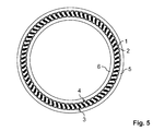
- Fig. 5 shows a freewheel with a freewheel installation element, which consists of a plurality of clamping bodies 1 and intermediate elements 2.
- the outer surface of the inner ring 6 forms the inner clamping track 4.
- the inner ring 6 and the outer ring 5 are arranged concentrically to one another and between the outer clamping track 3 and the inner clamping track 4 is the freewheel mounting element with the clamping bodies 1 and attached the intermediate elements 2.
Landscapes
- General Engineering & Computer Science (AREA)
- Engineering & Computer Science (AREA)
- Mechanical Engineering (AREA)
- Pulleys (AREA)
- Rolling Contact Bearings (AREA)
- Window Of Vehicle (AREA)
- Valve Device For Special Equipments (AREA)
- Braking Arrangements (AREA)
- Mechanical Operated Clutches (AREA)
- Transition And Organic Metals Composition Catalysts For Addition Polymerization (AREA)
- Medicines That Contain Protein Lipid Enzymes And Other Medicines (AREA)
- Springs (AREA)
- Clamps And Clips (AREA)
Priority Applications (8)
| Application Number | Priority Date | Filing Date | Title |
|---|---|---|---|
| AT08172346T ATE544967T1 (de) | 2008-12-19 | 2008-12-19 | Freilaufeinbauelement und freilauf |
| EP08172346A EP2199635B1 (fr) | 2008-12-19 | 2008-12-19 | Elément encastrable à roue libre et roue libre |
| DE112009003190T DE112009003190A5 (de) | 2008-12-19 | 2009-12-17 | Freilaufeinbauelement und freilauf |
| KR1020117014016A KR101606611B1 (ko) | 2008-12-19 | 2009-12-17 | 프리휠 인써트 엘리먼트 및 프리휠 |
| PCT/DE2009/075076 WO2010069308A1 (fr) | 2008-12-19 | 2009-12-17 | Ensemble encastré pour roue libre, et roue libre correspondante |
| JP2011541085A JP5555712B2 (ja) | 2008-12-19 | 2009-12-17 | フリーホイール挿入要素およびフリーホイール |
| US12/998,906 US8528713B2 (en) | 2008-12-19 | 2009-12-17 | Freewheel insert element and freewheel |
| TW098143562A TWI465653B (zh) | 2008-12-19 | 2009-12-18 | 飛輪構件與飛輪 |
Applications Claiming Priority (1)
| Application Number | Priority Date | Filing Date | Title |
|---|---|---|---|
| EP08172346A EP2199635B1 (fr) | 2008-12-19 | 2008-12-19 | Elément encastrable à roue libre et roue libre |
Publications (2)
| Publication Number | Publication Date |
|---|---|
| EP2199635A1 true EP2199635A1 (fr) | 2010-06-23 |
| EP2199635B1 EP2199635B1 (fr) | 2012-02-08 |
Family
ID=40612782
Family Applications (1)
| Application Number | Title | Priority Date | Filing Date |
|---|---|---|---|
| EP08172346A Not-in-force EP2199635B1 (fr) | 2008-12-19 | 2008-12-19 | Elément encastrable à roue libre et roue libre |
Country Status (8)
| Country | Link |
|---|---|
| US (1) | US8528713B2 (fr) |
| EP (1) | EP2199635B1 (fr) |
| JP (1) | JP5555712B2 (fr) |
| KR (1) | KR101606611B1 (fr) |
| AT (1) | ATE544967T1 (fr) |
| DE (1) | DE112009003190A5 (fr) |
| TW (1) | TWI465653B (fr) |
| WO (1) | WO2010069308A1 (fr) |
Citations (5)
| Publication number | Priority date | Publication date | Assignee | Title |
|---|---|---|---|---|
| US2520004A (en) * | 1946-12-23 | 1950-08-22 | Northern Ordnance Inc | Sprag type overrunning clutch |
| US2793729A (en) * | 1954-02-18 | 1957-05-28 | Gen Motors Corp | One-way clutch |
| US2803324A (en) * | 1954-05-03 | 1957-08-20 | Adiel Y Dodge | One-way clutch |
| DE4032915A1 (de) * | 1990-10-17 | 1992-04-23 | Hermann Grothe | Welle-nabe-verbindung |
| WO2003072968A1 (fr) * | 2002-02-28 | 2003-09-04 | Daxiong Lu | Roulement unidirectionnel |
Family Cites Families (14)
| Publication number | Priority date | Publication date | Assignee | Title |
|---|---|---|---|---|
| US2614670A (en) * | 1946-08-14 | 1952-10-21 | Jack & Heintz Prec Ind Inc | Sprag type overrunning clutch |
| US2624436A (en) * | 1947-01-02 | 1953-01-06 | Borg Warner | Sprag type clutch |
| US2812839A (en) * | 1954-02-18 | 1957-11-12 | Gen Motors Corp | One-way clutch |
| US3324980A (en) | 1965-07-06 | 1967-06-13 | Borg Warner | Elastomer cage for sprag members |
| DE2758841C2 (de) | 1977-12-30 | 1986-09-04 | Stieber Division Der Borg-Warner Gmbh, 6900 Heidelberg | Klemmkörper-Freilaufkupplung |
| US5052533A (en) * | 1987-02-09 | 1991-10-01 | Borg-Warner Corporation | One-way clutch energizing spring |
| US4998605A (en) * | 1990-02-12 | 1991-03-12 | Ferris Ernest A | Plastic cage for a one-way clutch |
| US5445255A (en) * | 1993-07-08 | 1995-08-29 | Borg-Warner Automotive, Inc. | Sprag one-way clutch with inertia resistance members |
| US5607036A (en) * | 1995-03-03 | 1997-03-04 | Borg-Warner Automotive, Inc. | One-way clutch with stretchable spring member |
| JP2001001364A (ja) * | 1999-06-21 | 2001-01-09 | Canon Inc | 樹脂成形品 |
| JP2006077937A (ja) * | 2004-09-13 | 2006-03-23 | Kazuo Ishikawa | ワンウェイクラッチ |
| JP2006292140A (ja) | 2005-04-14 | 2006-10-26 | Nsk Warner Kk | スプラグ型ワンウェイクラッチ |
| JP2008014427A (ja) | 2006-07-07 | 2008-01-24 | Ntn Corp | 一方向クラッチ付き軸受装置 |
| EP2199643B1 (fr) * | 2008-12-19 | 2016-06-08 | Paul Müller GmbH & Co. KG Unternehmensbeteiligungen | Amortisseur de vibrations de torsion et broche |
-
2008
- 2008-12-19 AT AT08172346T patent/ATE544967T1/de active
- 2008-12-19 EP EP08172346A patent/EP2199635B1/fr not_active Not-in-force
-
2009
- 2009-12-17 US US12/998,906 patent/US8528713B2/en not_active Expired - Fee Related
- 2009-12-17 JP JP2011541085A patent/JP5555712B2/ja not_active Expired - Fee Related
- 2009-12-17 KR KR1020117014016A patent/KR101606611B1/ko not_active Expired - Fee Related
- 2009-12-17 DE DE112009003190T patent/DE112009003190A5/de not_active Withdrawn
- 2009-12-17 WO PCT/DE2009/075076 patent/WO2010069308A1/fr not_active Ceased
- 2009-12-18 TW TW098143562A patent/TWI465653B/zh not_active IP Right Cessation
Patent Citations (5)
| Publication number | Priority date | Publication date | Assignee | Title |
|---|---|---|---|---|
| US2520004A (en) * | 1946-12-23 | 1950-08-22 | Northern Ordnance Inc | Sprag type overrunning clutch |
| US2793729A (en) * | 1954-02-18 | 1957-05-28 | Gen Motors Corp | One-way clutch |
| US2803324A (en) * | 1954-05-03 | 1957-08-20 | Adiel Y Dodge | One-way clutch |
| DE4032915A1 (de) * | 1990-10-17 | 1992-04-23 | Hermann Grothe | Welle-nabe-verbindung |
| WO2003072968A1 (fr) * | 2002-02-28 | 2003-09-04 | Daxiong Lu | Roulement unidirectionnel |
Also Published As
| Publication number | Publication date |
|---|---|
| US20110240434A1 (en) | 2011-10-06 |
| TWI465653B (zh) | 2014-12-21 |
| EP2199635B1 (fr) | 2012-02-08 |
| KR101606611B1 (ko) | 2016-03-25 |
| US8528713B2 (en) | 2013-09-10 |
| KR20110114537A (ko) | 2011-10-19 |
| JP2012512366A (ja) | 2012-05-31 |
| ATE544967T1 (de) | 2012-02-15 |
| WO2010069308A1 (fr) | 2010-06-24 |
| JP5555712B2 (ja) | 2014-07-23 |
| TW201030253A (en) | 2010-08-16 |
| DE112009003190A5 (de) | 2012-07-05 |
Similar Documents
| Publication | Publication Date | Title |
|---|---|---|
| DE19912431B4 (de) | Ausrückvorrichtung | |
| DE102011080167B4 (de) | Lagerkäfigsegment, Lagerkäfig und Verfahren zur Herstellung desselben | |
| DE2250003A1 (de) | Rotationskolbenmaschine, insbesondere maschine der fluegelzellenbauart, mit axial festgelegtem rotor | |
| DE102015219930B4 (de) | Freilaufvorrichtung für ein Kraftfahrzeug | |
| EP0503135B1 (fr) | Accouplement élastique à palier et limiteur de rotation combinés | |
| WO2007098745A1 (fr) | Ensemble roue dentée | |
| EP1041318A2 (fr) | Bague d'étanchéité | |
| EP2198175A2 (fr) | Roulement, ensemble palier à roulement et machine, en particulier appareil ménager électrique | |
| EP3377784A1 (fr) | Ensemble d'amortissement pour au moins une masse d'amortissement | |
| EP2199643B1 (fr) | Amortisseur de vibrations de torsion et broche | |
| WO2017162837A1 (fr) | Dispositif d'étanchéité, kit pour un dispositif d'étanchéité et procédé de fabrication d'un dispositif d'étanchéité | |
| DE102004060172A1 (de) | Kraftübertragungsvorrichtung | |
| WO2009124677A1 (fr) | Accouplement à roue libre | |
| EP1915545A1 (fr) | Dispositif de fixation pour une bague de roulement dans un boitier | |
| WO2013149914A1 (fr) | Support pour la fixation d'un composant sur un moteur à combustion interne, coussinet pour un tel support et système d'injection de carburant | |
| DE102008051242B4 (de) | Polrad und Montageverfahren hierfür | |
| DE602004006417T2 (de) | Vorrichtung und freilaufgehäuse | |
| EP2199635B1 (fr) | Elément encastrable à roue libre et roue libre | |
| EP3110680B1 (fr) | Arbre de direction pour véhicule automobile | |
| EP3251999B1 (fr) | Pneu pour poulie, poulie et procédé de fabrication d'un pneu pour poulie | |
| DE102010021409A1 (de) | Schaltbare Kupplung | |
| DE10323577A1 (de) | An einer kreiszylindrischen Oberfläche eines Aufnahmekörpers axial verschiebegesicherte Tellerfeder | |
| DE102017109441A1 (de) | Mehrwegkupplung | |
| EP2853766A2 (fr) | Couplage de rampes sphériques guidées sur un arbre de commande | |
| DE102015220725A1 (de) | Freilaufvorrichtung für ein Kraftfahrzeug |
Legal Events
| Date | Code | Title | Description |
|---|---|---|---|
| PUAI | Public reference made under article 153(3) epc to a published international application that has entered the european phase |
Free format text: ORIGINAL CODE: 0009012 |
|
| AK | Designated contracting states |
Kind code of ref document: A1 Designated state(s): AT BE BG CH CY CZ DE DK EE ES FI FR GB GR HR HU IE IS IT LI LT LU LV MC MT NL NO PL PT RO SE SI SK TR |
|
| AX | Request for extension of the european patent |
Extension state: AL BA MK RS |
|
| 17P | Request for examination filed |
Effective date: 20100928 |
|
| 17Q | First examination report despatched |
Effective date: 20101021 |
|
| AKX | Designation fees paid |
Designated state(s): AT BE BG CH CY CZ DE DK EE ES FI FR GB GR HR HU IE IS IT LI LT LU LV MC MT NL NO PL PT RO SE SI SK TR |
|
| RIC1 | Information provided on ipc code assigned before grant |
Ipc: F16D 41/07 20060101AFI20110714BHEP |
|
| GRAP | Despatch of communication of intention to grant a patent |
Free format text: ORIGINAL CODE: EPIDOSNIGR1 |
|
| GRAS | Grant fee paid |
Free format text: ORIGINAL CODE: EPIDOSNIGR3 |
|
| GRAA | (expected) grant |
Free format text: ORIGINAL CODE: 0009210 |
|
| AK | Designated contracting states |
Kind code of ref document: B1 Designated state(s): AT BE BG CH CY CZ DE DK EE ES FI FR GB GR HR HU IE IS IT LI LT LU LV MC MT NL NO PL PT RO SE SI SK TR |
|
| REG | Reference to a national code |
Ref country code: GB Ref legal event code: FG4D Free format text: NOT ENGLISH |
|
| REG | Reference to a national code |
Ref country code: AT Ref legal event code: REF Ref document number: 544967 Country of ref document: AT Kind code of ref document: T Effective date: 20120215 Ref country code: CH Ref legal event code: EP |
|
| REG | Reference to a national code |
Ref country code: DE Ref legal event code: R082 Ref document number: 502008006339 Country of ref document: DE Representative=s name: LOESCH, CHRISTOPH, DIPL.-WIRTSCH.-ING., DE Ref country code: DE Ref legal event code: R082 Ref document number: 502008006339 Country of ref document: DE Representative=s name: CHRISTOPH LOESCH, DE |
|
| REG | Reference to a national code |
Ref country code: DE Ref legal event code: R096 Ref document number: 502008006339 Country of ref document: DE Effective date: 20120405 |
|
| REG | Reference to a national code |
Ref country code: NL Ref legal event code: VDEP Effective date: 20120208 |
|
| LTIE | Lt: invalidation of european patent or patent extension |
Effective date: 20120208 |
|
| PG25 | Lapsed in a contracting state [announced via postgrant information from national office to epo] |
Ref country code: NO Free format text: LAPSE BECAUSE OF FAILURE TO SUBMIT A TRANSLATION OF THE DESCRIPTION OR TO PAY THE FEE WITHIN THE PRESCRIBED TIME-LIMIT Effective date: 20120508 Ref country code: HR Free format text: LAPSE BECAUSE OF FAILURE TO SUBMIT A TRANSLATION OF THE DESCRIPTION OR TO PAY THE FEE WITHIN THE PRESCRIBED TIME-LIMIT Effective date: 20120208 Ref country code: IS Free format text: LAPSE BECAUSE OF FAILURE TO SUBMIT A TRANSLATION OF THE DESCRIPTION OR TO PAY THE FEE WITHIN THE PRESCRIBED TIME-LIMIT Effective date: 20120608 Ref country code: NL Free format text: LAPSE BECAUSE OF FAILURE TO SUBMIT A TRANSLATION OF THE DESCRIPTION OR TO PAY THE FEE WITHIN THE PRESCRIBED TIME-LIMIT Effective date: 20120208 Ref country code: LT Free format text: LAPSE BECAUSE OF FAILURE TO SUBMIT A TRANSLATION OF THE DESCRIPTION OR TO PAY THE FEE WITHIN THE PRESCRIBED TIME-LIMIT Effective date: 20120208 |
|
| REG | Reference to a national code |
Ref country code: IE Ref legal event code: FD4D |
|
| PG25 | Lapsed in a contracting state [announced via postgrant information from national office to epo] |
Ref country code: PL Free format text: LAPSE BECAUSE OF FAILURE TO SUBMIT A TRANSLATION OF THE DESCRIPTION OR TO PAY THE FEE WITHIN THE PRESCRIBED TIME-LIMIT Effective date: 20120208 Ref country code: LV Free format text: LAPSE BECAUSE OF FAILURE TO SUBMIT A TRANSLATION OF THE DESCRIPTION OR TO PAY THE FEE WITHIN THE PRESCRIBED TIME-LIMIT Effective date: 20120208 Ref country code: FI Free format text: LAPSE BECAUSE OF FAILURE TO SUBMIT A TRANSLATION OF THE DESCRIPTION OR TO PAY THE FEE WITHIN THE PRESCRIBED TIME-LIMIT Effective date: 20120208 Ref country code: PT Free format text: LAPSE BECAUSE OF FAILURE TO SUBMIT A TRANSLATION OF THE DESCRIPTION OR TO PAY THE FEE WITHIN THE PRESCRIBED TIME-LIMIT Effective date: 20120608 Ref country code: GR Free format text: LAPSE BECAUSE OF FAILURE TO SUBMIT A TRANSLATION OF THE DESCRIPTION OR TO PAY THE FEE WITHIN THE PRESCRIBED TIME-LIMIT Effective date: 20120509 |
|
| PG25 | Lapsed in a contracting state [announced via postgrant information from national office to epo] |
Ref country code: CY Free format text: LAPSE BECAUSE OF FAILURE TO SUBMIT A TRANSLATION OF THE DESCRIPTION OR TO PAY THE FEE WITHIN THE PRESCRIBED TIME-LIMIT Effective date: 20120208 |
|
| PG25 | Lapsed in a contracting state [announced via postgrant information from national office to epo] |
Ref country code: CZ Free format text: LAPSE BECAUSE OF FAILURE TO SUBMIT A TRANSLATION OF THE DESCRIPTION OR TO PAY THE FEE WITHIN THE PRESCRIBED TIME-LIMIT Effective date: 20120208 Ref country code: SE Free format text: LAPSE BECAUSE OF FAILURE TO SUBMIT A TRANSLATION OF THE DESCRIPTION OR TO PAY THE FEE WITHIN THE PRESCRIBED TIME-LIMIT Effective date: 20120208 Ref country code: IE Free format text: LAPSE BECAUSE OF FAILURE TO SUBMIT A TRANSLATION OF THE DESCRIPTION OR TO PAY THE FEE WITHIN THE PRESCRIBED TIME-LIMIT Effective date: 20120208 Ref country code: RO Free format text: LAPSE BECAUSE OF FAILURE TO SUBMIT A TRANSLATION OF THE DESCRIPTION OR TO PAY THE FEE WITHIN THE PRESCRIBED TIME-LIMIT Effective date: 20120208 Ref country code: SI Free format text: LAPSE BECAUSE OF FAILURE TO SUBMIT A TRANSLATION OF THE DESCRIPTION OR TO PAY THE FEE WITHIN THE PRESCRIBED TIME-LIMIT Effective date: 20120208 Ref country code: EE Free format text: LAPSE BECAUSE OF FAILURE TO SUBMIT A TRANSLATION OF THE DESCRIPTION OR TO PAY THE FEE WITHIN THE PRESCRIBED TIME-LIMIT Effective date: 20120208 Ref country code: DK Free format text: LAPSE BECAUSE OF FAILURE TO SUBMIT A TRANSLATION OF THE DESCRIPTION OR TO PAY THE FEE WITHIN THE PRESCRIBED TIME-LIMIT Effective date: 20120208 |
|
| PG25 | Lapsed in a contracting state [announced via postgrant information from national office to epo] |
Ref country code: SK Free format text: LAPSE BECAUSE OF FAILURE TO SUBMIT A TRANSLATION OF THE DESCRIPTION OR TO PAY THE FEE WITHIN THE PRESCRIBED TIME-LIMIT Effective date: 20120208 |
|
| PLBE | No opposition filed within time limit |
Free format text: ORIGINAL CODE: 0009261 |
|
| STAA | Information on the status of an ep patent application or granted ep patent |
Free format text: STATUS: NO OPPOSITION FILED WITHIN TIME LIMIT |
|
| 26N | No opposition filed |
Effective date: 20121109 |
|
| REG | Reference to a national code |
Ref country code: DE Ref legal event code: R097 Ref document number: 502008006339 Country of ref document: DE Effective date: 20121109 |
|
| BERE | Be: lapsed |
Owner name: PAUL MULLER G.M.B.H. & CO. KG UNTERNEHMENSBETEILI Effective date: 20121231 |
|
| PG25 | Lapsed in a contracting state [announced via postgrant information from national office to epo] |
Ref country code: BG Free format text: LAPSE BECAUSE OF FAILURE TO SUBMIT A TRANSLATION OF THE DESCRIPTION OR TO PAY THE FEE WITHIN THE PRESCRIBED TIME-LIMIT Effective date: 20120508 Ref country code: MC Free format text: LAPSE BECAUSE OF NON-PAYMENT OF DUE FEES Effective date: 20121231 |
|
| PG25 | Lapsed in a contracting state [announced via postgrant information from national office to epo] |
Ref country code: BE Free format text: LAPSE BECAUSE OF NON-PAYMENT OF DUE FEES Effective date: 20121231 |
|
| PG25 | Lapsed in a contracting state [announced via postgrant information from national office to epo] |
Ref country code: ES Free format text: LAPSE BECAUSE OF FAILURE TO SUBMIT A TRANSLATION OF THE DESCRIPTION OR TO PAY THE FEE WITHIN THE PRESCRIBED TIME-LIMIT Effective date: 20120519 |
|
| PG25 | Lapsed in a contracting state [announced via postgrant information from national office to epo] |
Ref country code: MT Free format text: LAPSE BECAUSE OF FAILURE TO SUBMIT A TRANSLATION OF THE DESCRIPTION OR TO PAY THE FEE WITHIN THE PRESCRIBED TIME-LIMIT Effective date: 20120208 |
|
| PG25 | Lapsed in a contracting state [announced via postgrant information from national office to epo] |
Ref country code: TR Free format text: LAPSE BECAUSE OF FAILURE TO SUBMIT A TRANSLATION OF THE DESCRIPTION OR TO PAY THE FEE WITHIN THE PRESCRIBED TIME-LIMIT Effective date: 20120208 |
|
| PG25 | Lapsed in a contracting state [announced via postgrant information from national office to epo] |
Ref country code: LU Free format text: LAPSE BECAUSE OF NON-PAYMENT OF DUE FEES Effective date: 20121219 |
|
| PG25 | Lapsed in a contracting state [announced via postgrant information from national office to epo] |
Ref country code: HU Free format text: LAPSE BECAUSE OF FAILURE TO SUBMIT A TRANSLATION OF THE DESCRIPTION OR TO PAY THE FEE WITHIN THE PRESCRIBED TIME-LIMIT Effective date: 20081219 |
|
| REG | Reference to a national code |
Ref country code: FR Ref legal event code: PLFP Year of fee payment: 8 |
|
| REG | Reference to a national code |
Ref country code: FR Ref legal event code: PLFP Year of fee payment: 9 |
|
| REG | Reference to a national code |
Ref country code: FR Ref legal event code: PLFP Year of fee payment: 10 |
|
| PGFP | Annual fee paid to national office [announced via postgrant information from national office to epo] |
Ref country code: IT Payment date: 20191216 Year of fee payment: 12 Ref country code: FR Payment date: 20191218 Year of fee payment: 12 |
|
| PGFP | Annual fee paid to national office [announced via postgrant information from national office to epo] |
Ref country code: AT Payment date: 20191213 Year of fee payment: 12 |
|
| PGFP | Annual fee paid to national office [announced via postgrant information from national office to epo] |
Ref country code: GB Payment date: 20191220 Year of fee payment: 12 |
|
| PGFP | Annual fee paid to national office [announced via postgrant information from national office to epo] |
Ref country code: CH Payment date: 20201222 Year of fee payment: 13 |
|
| REG | Reference to a national code |
Ref country code: AT Ref legal event code: MM01 Ref document number: 544967 Country of ref document: AT Kind code of ref document: T Effective date: 20201219 |
|
| GBPC | Gb: european patent ceased through non-payment of renewal fee |
Effective date: 20201219 |
|
| PG25 | Lapsed in a contracting state [announced via postgrant information from national office to epo] |
Ref country code: AT Free format text: LAPSE BECAUSE OF NON-PAYMENT OF DUE FEES Effective date: 20201219 Ref country code: IT Free format text: LAPSE BECAUSE OF NON-PAYMENT OF DUE FEES Effective date: 20201219 Ref country code: FR Free format text: LAPSE BECAUSE OF NON-PAYMENT OF DUE FEES Effective date: 20201231 |
|
| PG25 | Lapsed in a contracting state [announced via postgrant information from national office to epo] |
Ref country code: GB Free format text: LAPSE BECAUSE OF NON-PAYMENT OF DUE FEES Effective date: 20201219 |
|
| PGFP | Annual fee paid to national office [announced via postgrant information from national office to epo] |
Ref country code: DE Payment date: 20220217 Year of fee payment: 14 |
|
| REG | Reference to a national code |
Ref country code: CH Ref legal event code: PL |
|
| PG25 | Lapsed in a contracting state [announced via postgrant information from national office to epo] |
Ref country code: LI Free format text: LAPSE BECAUSE OF NON-PAYMENT OF DUE FEES Effective date: 20211231 Ref country code: CH Free format text: LAPSE BECAUSE OF NON-PAYMENT OF DUE FEES Effective date: 20211231 |
|
| P01 | Opt-out of the competence of the unified patent court (upc) registered |
Effective date: 20230516 |
|
| REG | Reference to a national code |
Ref country code: DE Ref legal event code: R119 Ref document number: 502008006339 Country of ref document: DE |
|
| PG25 | Lapsed in a contracting state [announced via postgrant information from national office to epo] |
Ref country code: DE Free format text: LAPSE BECAUSE OF NON-PAYMENT OF DUE FEES Effective date: 20230701 |