EP2199643A1 - Drehschwingungsdämpfer und Spindel - Google Patents
Drehschwingungsdämpfer und Spindel Download PDFInfo
- Publication number
- EP2199643A1 EP2199643A1 EP08172384A EP08172384A EP2199643A1 EP 2199643 A1 EP2199643 A1 EP 2199643A1 EP 08172384 A EP08172384 A EP 08172384A EP 08172384 A EP08172384 A EP 08172384A EP 2199643 A1 EP2199643 A1 EP 2199643A1
- Authority
- EP
- European Patent Office
- Prior art keywords
- torsional vibration
- vibration damper
- intermediate elements
- clamping
- machine part
- Prior art date
- Legal status (The legal status is an assumption and is not a legal conclusion. Google has not performed a legal analysis and makes no representation as to the accuracy of the status listed.)
- Granted
Links
Images


Classifications
-
- F—MECHANICAL ENGINEERING; LIGHTING; HEATING; WEAPONS; BLASTING
- F16—ENGINEERING ELEMENTS AND UNITS; GENERAL MEASURES FOR PRODUCING AND MAINTAINING EFFECTIVE FUNCTIONING OF MACHINES OR INSTALLATIONS; THERMAL INSULATION IN GENERAL
- F16F—SPRINGS; SHOCK-ABSORBERS; MEANS FOR DAMPING VIBRATION
- F16F15/00—Suppression of vibrations in systems; Means or arrangements for avoiding or reducing out-of-balance forces, e.g. due to motion
- F16F15/10—Suppression of vibrations in rotating systems by making use of members moving with the system
- F16F15/16—Suppression of vibrations in rotating systems by making use of members moving with the system using a fluid or pasty material
- F16F15/167—Suppression of vibrations in rotating systems by making use of members moving with the system using a fluid or pasty material having an inertia member, e.g. ring
-
- F—MECHANICAL ENGINEERING; LIGHTING; HEATING; WEAPONS; BLASTING
- F16—ENGINEERING ELEMENTS AND UNITS; GENERAL MEASURES FOR PRODUCING AND MAINTAINING EFFECTIVE FUNCTIONING OF MACHINES OR INSTALLATIONS; THERMAL INSULATION IN GENERAL
- F16F—SPRINGS; SHOCK-ABSORBERS; MEANS FOR DAMPING VIBRATION
- F16F15/00—Suppression of vibrations in systems; Means or arrangements for avoiding or reducing out-of-balance forces, e.g. due to motion
- F16F15/10—Suppression of vibrations in rotating systems by making use of members moving with the system
- F16F15/12—Suppression of vibrations in rotating systems by making use of members moving with the system using elastic members or friction-damping members, e.g. between a rotating shaft and a gyratory mass mounted thereon
- F16F15/121—Suppression of vibrations in rotating systems by making use of members moving with the system using elastic members or friction-damping members, e.g. between a rotating shaft and a gyratory mass mounted thereon using springs as elastic members, e.g. metallic springs
- F16F15/124—Elastomeric springs
-
- F—MECHANICAL ENGINEERING; LIGHTING; HEATING; WEAPONS; BLASTING
- F16—ENGINEERING ELEMENTS AND UNITS; GENERAL MEASURES FOR PRODUCING AND MAINTAINING EFFECTIVE FUNCTIONING OF MACHINES OR INSTALLATIONS; THERMAL INSULATION IN GENERAL
- F16D—COUPLINGS FOR TRANSMITTING ROTATION; CLUTCHES; BRAKES
- F16D41/00—Freewheels or freewheel clutches
- F16D41/06—Freewheels or freewheel clutches with intermediate wedging coupling members between an inner and an outer surface
- F16D41/069—Freewheels or freewheel clutches with intermediate wedging coupling members between an inner and an outer surface the intermediate members wedging by pivoting or rocking, e.g. sprags
- F16D41/07—Freewheels or freewheel clutches with intermediate wedging coupling members between an inner and an outer surface the intermediate members wedging by pivoting or rocking, e.g. sprags between two cylindrical surfaces
-
- F—MECHANICAL ENGINEERING; LIGHTING; HEATING; WEAPONS; BLASTING
- F16—ENGINEERING ELEMENTS AND UNITS; GENERAL MEASURES FOR PRODUCING AND MAINTAINING EFFECTIVE FUNCTIONING OF MACHINES OR INSTALLATIONS; THERMAL INSULATION IN GENERAL
- F16F—SPRINGS; SHOCK-ABSORBERS; MEANS FOR DAMPING VIBRATION
- F16F15/00—Suppression of vibrations in systems; Means or arrangements for avoiding or reducing out-of-balance forces, e.g. due to motion
- F16F15/10—Suppression of vibrations in rotating systems by making use of members moving with the system
Definitions
- the invention relates to a torsional vibration damper and a spindle.
- Torsional vibration dampers are used to suppress or reduce torsional vibration, in particular to keep vibration amplitudes small and to influence the resonance frequency.
- torsional vibrations is meant in particular oscillating rotational movements about an axis. They are stimulated by periodic, jerky or temporally random torques. Torsional vibrations are generally undesirable phenomena and interfere with the running of machines and can lead to disturbances.
- Object of the present invention is to provide a particularly simple design and at the same time effective torsional vibration damper and a particularly advantageous stored spindle.
- the torsional vibration damper according to the invention for coupling two coaxially arranged machine parts in particular for coupling a first cylindrical inner surface of a first machine part with a cylindrical outer surface of a second machine part, has a plurality of clamping bodies and a plurality of intermediate elements on, wherein the intermediate elements have a higher elasticity than the clamping body and are arranged between adjacent clamping bodies.
- a torsional vibration damper which transmits to a safe torque and on the other hand to a certain extent is torsionally elastic.
- the torsional elasticity or the maximum transmittable torque of the torsional vibration damper can be influenced.
- the increased elasticity of the intermediate elements in comparison to the clamping bodies increases the deformability of the torsional vibration damper and thereby facilitates its installation between the machine parts to be coupled.
- the damping of torsional vibrations is achieved in the torsional vibration damper according to the invention in particular by internal friction in the intermediate element. Therefore, the material or have the materials of which the intermediate element is constructed, preferably a high internal damping. In particular, the damping properties of, for example, rubber and of plastics filled with certain fillers are useful here. In a particularly preferred manner, a fibrous material can be used as a filler within the intermediate elements to enhance the internal damping of the intermediate elements.
- the material or materials from which the intermediate element is constructed preferably have a Shore hardness of 50 Shore B to 100 Shore B, in particular greater than 70 Shore B.
- the Shore hardness is a widely used parameter for testing of plastics and Elastomers and is described in the standards DIN 53505, ISO 868 and ISO 7619.
- the clamping body are in particular as clamping body as in freewheeling, d. H. in directional couplings, which transmit in one direction a torque by adhesion or support and allow idle in the opposite direction, apply, designed.
- the clamping bodies are preferably made of a metallic material, e.g. from a steel material. Accordingly, the intermediate elements then have an elasticity which is higher than the elasticity of metallic materials.
- the intermediate elements completely fill the region present in the radial direction between the clamping bodies, that is to say the gap between two adjacent clamping bodies. Ie. the existing in the circumferential direction between the clamping bodies area is completely filled by the intermediate elements.
- the cylindrical inner surface or the cylindrical outer surface of the machine parts to be coupled are in contact with the intermediate elements over their entire circumference. This leads to a particularly uniform and secure contact of the torsional vibration damper with the machine parts to be coupled.
- each clamping body has an outer contact surface for forming a frictional contact with an outer clamping track, in particular with a cylindrical inner surface of a first machine part, and an inner contact surface for forming a frictional contact with an inner clamping track, in particular with a cylindrical outer surface of a second machine part ,
- the region located in the circumferential direction between the clamping bodies that is to say the intermediate space between the clamping bodies, is not completely filled with the intermediate elements.
- the torsional vibration damper can be designed in particular as a freewheel, ie transmit or support a torque by frictional connection in one direction and allow idling in the opposite direction.
- the intermediate elements of the torsional vibration damper according to the invention are designed to fix the clamping body in position and cushion.
- a simultaneous fixing and cushioning of the clamping body by the intermediate elements a particularly compact construction of the torsional vibration damper is possible.
- the intermediate elements are connected to the clamping bodies.
- the intermediate elements can be materially connected to the clamping bodies, which leads to a particularly reliable and stable composite of intermediate elements and clamping bodies and thereby improves, for example, the handling of the torsional vibration damper.
- the cohesive connection can be designed, for example, as an adhesive connection.
- the intermediate elements may be configured as a casting compound or a plurality of casting compounds and the cohesive connection by a casting process in which the clamping body are - at least partially - enclosed by the casting compound or casting compounds produced. It is also possible, the intermediate elements of an injection molding compound or
- the intermediate elements in their contour correspond to the contour of the adjacent clamping bodies.
- Such a configuration of the contour allows a particularly reliable connection between the intermediate element and the adjacent thereto clamping body.
- At least one clamping body is arranged tilted relative to the radial direction between adjacent intermediate elements.
- two adjacently arranged clamping bodies are each tilted in the opposite direction relative to the radial direction in the intermediate elements integrated.
- the intermediate elements may consist of several different materials.
- the elasticity of at least one intermediate element varies along the radial direction.
- This variation in the elasticity can be achieved for example by the construction of the intermediate element by different materials or by a gradual variation of the elasticity of the material used.
- the variation of the elasticity also increases the adaptability of the torsional vibration damper.
- the intermediate elements in preferred embodiments may be at least partially made of silicone material, thermoplastic polymers, vulcanized rubber, thermosetting polymers (e.g., synthetic resin), or a mixture of the foregoing materials.
- all intermediate elements may have the same material composition.
- the torsional vibration damper is strip-shaped.
- the production of the torsional vibration damper is possible as an endless belt. After the production of the torsional vibration damper can then be divided to the desired circumferential length and between two coaxially arranged machine parts, in particular between a cylindrical inner surface of a first machine part and a cylindrical outer surface of a second machine part, inserted.
- the torsional vibration damper is annular. This allows the torsional vibration damper particularly easy to be arranged between two coaxially arranged machine elements.
- the spindle according to the invention is designed in particular as a motor spindle and has a torsional vibration damper according to the invention.
- Fig. 1 shows a torsional vibration damper 1 with a plurality of clamping bodies 2 and intermediate elements 3, wherein in the figures usually only one clamping body 2 and an intermediate element 3 is provided with a reference numeral.
- the torsional vibration damper 1 is annular trained and the clamping body 2 are evenly distributed over the circumference.
- the torsional vibration damper 1 is disposed between a cylindrical outer surface of a machine part 4 and a cylindrical inner surface of a machine part 5.
- the two machine parts 4 and 5 are aligned concentrically with each other.
- the clamping body 2 are arranged tilted relative to the radial direction between adjacent intermediate elements 3. More precisely, the clamping bodies 2 are embedded counterclockwise in the intermediate elements 3, so that in particular a torque can be transmitted in a clockwise direction.
- Fig. 2 shows a further torsional vibration damper 1 with a plurality of clamping bodies 2 and intermediate elements 3.
- the torsional vibration damper 1 in Fig. 2 is also annular and the clamping body 2 are evenly distributed over the circumference.
- the torsional vibration damper 1 is also arranged between a cylindrical outer surface of a machine part 4 and a cylindrical inner surface of a machine part 5. In each case two adjacent clamping body 2 are hereby tilted against each other embedded in the intermediate elements. This makes it possible to transmit high torque in both directions of rotation.
- torsional vibration dampers 1 fill the intermediate elements 3 in the radial direction between the clamping bodies 2 existing area completely.
- both the clamping body 2 and the intermediate elements 3 form a contact with the corresponding cylindrical surfaces of the machine parts 4 and 5 and the cylindrical outer surface of the machine part 4 and the cylindrical inner surface of a machine part 5 are alternately over its entire circumference - of a clamping body. 2 and an intermediate elements 3 - contacted.
- Fig. 3 zigt another embodiment of the torsional vibration damper 1 with a plurality of equidistantly distributed clamping elements 2 and intermediate elements 3.
- the intermediate elements 3 fill the region located in the radial direction between the clamping elements 2 is not complete.
- the cylindrical outer surface of the machine part 4 or the cylindrical inner surface of the machine part 5 is contacted only by the clamping elements 2 and the torsional vibration damper 1 can also act as a freewheel.
- Such torsional vibration dampers 1, which can serve as freewheel at the same time, are also referred to below as one-way torsional vibration dampers.
- Fig. 4 shows a section of a further embodiment of the torsional vibration damper 1.
- the in Fig. 4 shown torsional vibration damper 1 is formed band-shaped and can be divided to the desired circumferential length and inserted between the cylindrical outer surface of the machine part 4 and the cylindrical inner surface of the machine part 5.
- the intermediate element 3 substantially completely fills the space located in the circumferential direction between two adjacent clamping bodies 12, so that the contour of the clamping body 12 is completely in contact with the intermediate element 3a or 3b except for the outer contact surface 12a and the inner contact surface 12b.
- the outer contact surface 12a and the inner contact surface 12b form clamping contact surfaces, which form a clamping contact with the cylindrical inner surface of the machine part 5 or with the cylindrical outer surfaces of the machine part 4.
- Fig. 4 shows the clamping body 12 at the same time a first position and - the first position partially overlapping - in a second position.
- the clamping body 12 In the second position are the clamping body 12, when the external contact surface 12a by forming a frictional contact in the Direction of rotation V is rotated relative to the inner contact surface 12b.
- the adjacent to the respective clamping bodies 12 intermediate elements 3 - for example, the intermediate elements 3a and 3b with respect to the in Fig. 4 provided with the reference clamp body 12 - are firmly connected to the clamp body and deform due to their elastic material behavior in the displacement of the clamp body 12 between the two positions accordingly.
- an attenuation of the torsional vibrations occurring is generated due to their internal friction.
- the adjacent intermediate elements 3a and 3b made of different materials, in particular of materials with different elasticity.
- Fig. 5 shows a further embodiment of a torsional vibration damper 1.
- the adjacent clamping bodies 22 and 32 are tilted in opposite directions in the intermediate element 3 formed.
- Fig. 5 shown torsional vibration damper designed such that it can transmit an increased torque in both directions of rotation.
- Fig. 4 are the clamp body 22 and 32 in Fig. 5 at the same time in a first position and - the first position partially overlapping - in a second position in which the clamping body 22 and 32 were brought by a displacement in the direction of rotation V, shown.
- the clamping bodies 22 and the intermediate element 3 deforms in Fig. 5 accordingly, whereby the damping of the torsional vibrations occurring is made possible.
- Fig. 6 and Fig. 7 is an example of an application of the torsional vibration damper 1 shown.
- a pulley 6 is seated with sliding fit on the shaft 7. Between the cylindrical inner surface of the pulley 6 and the cylindrical outer surface of the shaft 7, a torsional vibration damper 1 is mounted. This ensures unbalance and impact-free assembly of the pulley 6.
- the torsional vibration damper 1 allows the transmission of torque between the pulley 6 and the shaft 7. At the same time it is ensured by the torsional vibration damper 1 that any torsional vibrations occurring are damped.
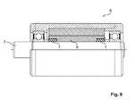
- Fig. 8 shows a partial sectional view of another installation example in which two torsional vibration damper 1 in an electric motor 8, as used for example in motor spindles is installed.
- the stator 9 of the electric motor 8 is not pressed onto the shaft 7, but sits with sliding fit on the shaft 7.
- the torque generated by the electric motor 8 is transmitted via the torsional vibration damper 1 to the shaft 7.
Landscapes
- Engineering & Computer Science (AREA)
- General Engineering & Computer Science (AREA)
- Mechanical Engineering (AREA)
- Physics & Mathematics (AREA)
- Acoustics & Sound (AREA)
- Aviation & Aerospace Engineering (AREA)
- Vibration Prevention Devices (AREA)
- Motor Or Generator Frames (AREA)
- Vibration Dampers (AREA)
- Connection Of Motors, Electrical Generators, Mechanical Devices, And The Like (AREA)
- Pulleys (AREA)
Abstract
Description
- Die Erfindung betrifft einen Drehschwingungsdämpfer und eine Spindel.
- Drehschwingungsdämpfer dienen zur Unterdrückung bzw. Verminderung von Drehschwingen, um vor allem Schwingungsamplituden klein zu halten und die Resonanzfrequenz zu beeinflussen. Unter Drehschwingungen versteht man hierbei insbesondere oszillierende Drehbewegungen um eine Achse. Sie werden angeregt durch periodische, stoßartige oder zeitlich zufällig verlaufende Drehmomente. Drehschwingungen sind allgemein unerwünschte Erscheinungen und stören den Lauf von Maschinen und können zu Störungen führen.
- Aufgabe der vorliegenden Erfindung ist es, einen besonders einfach aufgebauten und zugleich wirkungsvollen Drehschwingungsdämpfer sowie eine besonders vorteilhaft gelagerte Spindel zur Verfügung zu stellen.
- Diese Aufgabe wird für den Drehschwingungsdämpfer durch die Merkmale des Patentanspruchs 1 gelöst. Vorteilhafte Ausführungsformen des Drehschwingungsdämpfers sind in den Unteransprüchen 2 - 13 beschrieben. Für die Motorspindel wird die Aufgabe durch die Merkmale des Patentanspruchs 14 gelöst.
- Der erfindungsgemäßen Drehschwingungsdämpfer zur Kopplung zweier koaxial zueinander angeordneter Maschinenteile, insbesondere zur Koppelung einer ersten zylindrischen Innenfläche eines ersten Maschinenteils mit einer zylindrischen Außenfläche eines zweiten Maschinenteils, weist eine Vielzahl von Klemmkörpern und eine Vielzahl von Zwischenelementen auf, wobei die Zwischenelemente eine höhere Elastizität als die Klemmkörper besitzen und zwischen benachbarten Klemmkörpern angeordnet sind.
- Durch einen derartigen Aufbau wird ein Drehschwingungsdämpfer geschaffen, der zum einen sicher Drehmomente überträgt und zum anderen in bestimmten Maß drehelastisch ist. Je nach Elastizität der verwendeten Zwischenelemente bzw. Ausgestaltung der verwendeten Klemmelemente kann die Drehelastizität bzw. das maximal übertragbare Drehmoment des Drehschwingungsdämpfers beeinflusst werden.
- Außerdem erhöht die im Vergleich zu den Klemmkörpern höhere Elastizität der Zwischenelemente die Verformbarkeit des Drehschwingungsdämpfers und erleichtert dadurch dessen Einbau zwischen den zu koppelnden Maschinenteilen.
- Die Dämpfung von Drehschwingungen wird beim erfindungsgemäßen Drehschwingungsdämpfer insbesondere durch innere Reibung im Zwischenelement erzielt. Daher weist der Werkstoff bzw. weisen die Werkstoffe, aus denen das Zwischenelement aufgebaut ist, in bevorzugter Weise eine hohe Eigendämpfung auf. Hierbei sind insbesondere die Dämpfungseigenschaften von beispielsweise Gummi und von mit bestimmten Füllstoffen gefüllten Kunststoffen von Nutzen. In besonders bevorzugter Weise kann zur Verstärkung der Eigendämpfung der Zwischenelemente ein faseriges Material als Füllstoff innerhalb der Zwischenelemente verwendet werden.
- Der Werkstoff bzw. die Werkstoffe, aus dem das Zwischenelement aufgebaut ist, besitzen in bevorzugter Weise eine Shorehärte von 50 Shore B bis 100 Shore B, insbesondere von größer 70 Shore B. Die Shore-Härte ist eine weit verbreitete Kenngröße zur Prüfung von Kunststoffen und Elastomeren und ist in den Normen DIN 53505, ISO 868 und ISO 7619 beschrieben.
- Die Klemmkörper sind insbesondere als Klemmkörper wie sie in Freiläufen, d. h. in Richtungskupplungen, die in eine Richtung ein Drehmoment durch Kraftschluss übertragen bzw. abstützen und in der Gegenrichtung Leerlauf zulassen, Anwendung finden, ausgestaltet. Ferner bestehen die Klemmkörper bevorzugt aus einem metallischen Material, z.B. aus einem Stahlwerkstoff. Entsprechend weisen die Zwischenelemente dann eine Elastizität auf, die höher ist als die Elastizität von metallischen Werkstoffen.
- In einer bevorzugten Ausführungsform füllen die Zwischenelemente den in radialer Richtung zwischen den Klemmkörpern vorhandenen Bereich, also den Zwischenraum zwischen zwei benachbarten Klemmkörpern, vollständig aus. D. h. der in Umfangsrichtung zwischen den Klemmkörpern vorhandene Bereich ist vollständig durch die Zwischenelemente ausgefüllt. Dadurch stehen die zylindrische Innenfläche bzw. die zylindrische Außenfläche der zu koppelnden Maschinenteile über ihren gesamten Umfang mit den Zwischenelementen in Kontakt. Dies führt zu einer besonders gleichmäßigen und sicheren Kontaktierung des Drehschwingungsdämpfers mit den zu koppelnden Maschinenteilen.
- In einer weiteren bevorzugten Ausführungsform weist jeder Klemmkörper eine Außenkontaktfläche zur Ausbildung eines reibschlüssigen Kontakts mit einer Außenklemmbahn, insbesondere mit einer zylindrischen Innenfläche eines ersten Maschinenteils, und einer Innenkontaktfläche zur Ausbildung eines reibschlüssigen Kontakts mit einer Innenklemmbahn, insbesondere mit einer zylindrischen Außenfläche eines zweiten Maschinenteils, auf.
- In einer weiteren bevorzugten Ausführungsform ist der in Umfangsrichtung zwischen den Klemmkörpern gelegene Bereich, also der Zwischenraum zwischen den Klemmkörpern, nicht vollständig mit den Zwischenelementen gefüllt. Dadurch bleiben vermehrt Kontaktflächen der Klemmkörper frei, die einen reibschlüssigen Kontakt mit den zu koppelnden Maschinenteilen eingehen können. Hierbei kann der Drehschwingungsdämpfer insbesondere als Freilauf ausgestaltetet sein, d.h. in eine Richtung ein Drehmoment durch Kraftschluss übertragen bzw. abstützen und in der Gegenrichtung Leerlauf zulassen.
- In vorteilhafter Weise sind die Zwischenelemente des erfindungsgemäßen Drehschwingungsdämpfers ausgebildet, die Klemmkörper in ihrer Lage zu fixieren und abzufedern. Durch ein gleichzeitiges Fixieren und Abfedern der Klemmkörper durch die Zwischenelemente ist eine besonders kompakte Bauweise des Drehschwingungsdämpfers möglich.
- Bestehen die Zwischenelemente aus einem elastischen Material mit hoher Eigendämpfung, z. B. aus Kautschuk, dann führt die Kippbewegung beim Einrollen der Klemmkörper zu einer Verformung des zwischen den Klemmkörpern angeordneten dämpfenden Materials der Zwischenelemente und damit zum Entzug von Schwingungsenergie, was zu einer besonders ausgeprägten Dämpfung durch den Drehschwingungsdämpfer führt.
- In einer vorteilhaften Ausführungsform sind die Zwischenelemente mit den Klemmkörpern verbunden. Insbesondere können die Zwischenelemente stoffschlüssig mit den Klemmkörpern verbunden sein, was zu einem besonders zuverlässigen und stabilen Verbund von Zwischenelementen und Klemmkörpern führt und dadurch beispielsweise die Handhabbarkeit des Drehschwingungsdämpfers verbessert. Hierbei kann die stoffschlüssige Verbindung beispielsweise als Klebeverbindung ausgeführt sein. Auch können die Zwischenelemente als Gießmasse bzw. mehrere Gießmassen ausgestaltet sein und die stoffschlüssige Verbindung durch einen Gießprozess, in dem die Klemmkörper - zumindest teilweise - durch die Gießmasse bzw. Gießmassen umschlossen werden, hergestellt werden. Auch ist es möglich, die Zwischenelemente aus einer Spritzgussmasse bzw.
- Spritzgussmassen herzustellen und die Zwischenelemente mit Hilfe eines Spritzgussprozesses mit den Klemmkörpern zu verbinden.
- In einer weiteren vorteilhaften Ausführungsform entsprechen die Zwischenelemente in ihrer Kontur der Kontur der benachbarten Klemmkörper. Eine derartige Ausgestaltung der Kontur erlaubt eine besonders zuverlässige Verbindung zwischen dem Zwischenelement und den an diesen angrenzenden Klemmkörper.
- In einer vorteilhaften Ausführungsform ist mindestens ein Klemmkörper gegenüber der radialen Richtung verkippt zwischen benachbarten Zwischenelementen angeordnet. Dadurch kann die Dämpfungswirkung sowie das maximal übertragbare Drehmoment des Drehschwingungsdämpfers von der Richtung der Relativbewegung zwischen den zu koppelnden Maschinenteilen abhängig gemacht werden.
- In einer weiteren vorteilhaften Ausführungsform sind zwei benachbart zueinander angeordnete Klemmkörper jeweils in entgegengesetzter Richtung gegenüber der radialen Richtung verkippt in die Zwischenelemente eingebunden. Dadurch kann ebenfalls die Dämpfungswirkung sowie das maximal übertragbare Drehmoment des Drehschwingungsdämpfers von der Richtung der Relativbewegung zwischen den zu koppelnden Maschinenteilen abhängig gemacht werden.
- In vorteilhafter Weise können die Zwischenelemente aus mehreren unterschiedlichen Werkstoffen bestehen. Hierbei ist es zum einen möglich, dass beispielsweise benachbart zueinander liegende Zwischenelemente aus unterschiedlichen Werkstoffen bestehen, zum anderen ist es auch möglich, dass ein Zwischenelement selbst aus verschiedenen Werkstoffen aufgebaut ist. Insgesamt wird dadurch die Variabilität und Anpassbarkeit des Drehschwingungsdämpfers an verschiedene Anwendungsfälle erhöht.
- In einer weiteren vorteilhaften Ausführungsform variiert die Elastizität mindestens eines Zwischenelements entlang der radialen Richtung. Diese Variation in der Elastizität kann beispielsweise durch den Aufbau des Zwischenelements durch verschiedene Werkstoffe bzw. durch eine graduelle Variation der Elastizität des verwendeten Werkstoffs erreicht werden. Die Variation der Elastizität erhöht ebenfalls die Anpassbarkeit des Drehschwingungsdämpfers.
- Je nach gewünschtem Einsatzgebiet und je nach gewünschter Elastizität können die Zwischenelemente in bevorzugten Ausführungsformen zumindest teilweise aus Silikonwerkstoff, aus thermoplastischen Polymeren, aus vulkanisiertem Kautschuk, aus duroplastischen Polymeren (z.B. Kunstharz) oder aus einer Mischung der vorgenannten Werkstoffe hergestellt sein. Hierbei können sämtliche Zwischenelemente die gleiche Werkstoffzusammensetzung aufweisen. Es ist jedoch auch möglich, die Werkstoffzusammensetzung von Zwischenelement zu Zwischenelement zu variieren. Dies erhöht die Variabilität des Drehschwingungsdämpfers sowie dessen Anpassbarkeit an verschiedene Anwendungsfälle.
- In einer weiteren vorteilhaften Ausführungsform ist der Drehschwingungsdämpfer bandförmig ausgebildet. Hierdurch ist die Herstellung des Drehschwingungsdämpfers als endloses Band möglich. Nach der Herstellung kann der Drehschwingungsdämpfer dann auf die gewünschte Umlauflänge zerteilt und zwischen zwei koaxial zueinander angeordneten Maschinenteilen, insbesondere zwischen eine zylindrische Innenfläche eines ersten Maschinenteils und eine zylindrische Außenfläche eines zweiten Maschinenteils, eingelegt werden.
- In einer weiteren vorteilhaften Ausführungsform ist der Drehschwingungsdämpfer ringförmig ausgebildet. Dadurch kann der Drehschwingungsdämpfer besonders einfach zwischen zwei koaxial angeordnete Maschinenelemente angeordnet werden.
- Die erfindungsgemäße Spindel ist insbesondere als Motorspindel ausgebildet und weist einen erfindungsgemäßen Drehschwingungsdämpfer auf.
- Die Erfindung ist anhand von Ausführungsbeispielen in den Zeichnungsfiguren weiter erläutert. Es zeigen:
- Fig. 1
- eine erste Ausführungsform des Drehschwingungsdämpfers;
- Fig. 2
- eine zweite Ausführungsform des Drehschwingungsdämpfers;
- Fig. 3
- eine dritte Ausführungsform des Drehschwingungsdämpfers;
- Fig. 4
- einen Ausschnitt aus einer vierten Ausführungsform des Drehschwingungsdämpfers;
- Fig. 5
- einen Ausschnitt aus einer fünften Ausführungsform des Drehschwingungsdämpfers;
- Fig. 6
- einen in eine Riemenscheibe eingebauten Drehschwingungsdämpfer;
- Fig. 7
- einen in einen Elektromotor eingebauten Drehschwingungsdämpfer.
-
Fig. 1 zeigt einen Drehschwingungsdämpfer 1 mit einer Vielzahl von Klemmkörpern 2 und Zwischenelementen 3, wobei in den Figuren in der Regel jeweils nur ein Klemmkörper 2 und ein Zwischenelement 3 mit einem Bezugszeichen versehen ist. Der Drehschwingungsdämpfer 1 ist ringförmig ausgebildet und die Klemmkörper 2 sind gleichmäßig über den Umfang verteilt. Der Drehschwingungsdämpfer 1 ist zwischen einer zylindrischen Außenfläche eines Maschinenteils 4 und einer zylindrischen Innenfläche eines Maschinenteils 5 angeordnet. Die beiden Maschinenteile 4 und 5 sind konzentrisch zueinander ausgerichtet. Die Klemmkörper 2 sind gegenüber der radialen Richtung verkippt zwischen benachbarten Zwischenelementen 3 angeordnet. Genauer sind die Klemmkörper 2 entgegen dem Uhrzeigersinn in den Zwischenelementen 3 eingebettet, sodass insbesondere ein Drehmoment im Uhrzeigersinn übertragen werden kann. -
Fig. 2 zeigt einen weiteren Drehschwingungsdämpfer 1 mit einer Vielzahl von Klemmkörpern 2 und Zwischenelementen 3. Der Drehschwingungsdämpfer 1 inFig. 2 ist ebenfalls ringförmig ausgebildet und die Klemmkörper 2 sind gleichmäßig über den Umfang verteilt. Der Drehschwingungsdämpfer 1 ist ebenfalls zwischen einer zylindrischen Außenfläche eines Maschinenteils 4 und einer zylindrischen Innenfläche eines Maschinenteils 5 angeordnet. Jeweils zwei benachbarte Klemmkörper 2 sind hierbei gegeneinander verkippt in die Zwischenelemente eingebettet. Dadurch besteht die Möglichkeit in beide Drehrichtungen ein hohes Drehmoment zu übertragen. - In den in
Fig. 1 und Fig. 2 dargestellten Drehschwingungsdämpfern 1 füllen die Zwischenelemente 3 den in radialer Richtung zwischen den Klemmkörpern 2 vorhandenen Bereich vollständig aus. Dadurch bilden sowohl die Klemmkörper 2 als auch die Zwischenelemente 3 einen Kontakt zu den entsprechenden zylindrischen Flächen der Maschinenteile 4 bzw. 5 aus und die zylindrischen Außenfläche des Maschinenteils 4 und die zylindrische Innenfläche eines Maschinenteils 5 werden über ihren gesamten Umfang - abwechselnd von einem Klemmkörper 2 und einem Zwischenelemente 3 - kontaktiert. -
Fig. 3 zigt eine weitere Ausführungsform des Drehschwingungsdämpfers 1 mit einer Vielzahl von äquidistant verteilten Klemmelementen 2 und Zwischenelementen 3. Im Gegensatz zu den inFig. 1 und inFig. 2 dargestellten Ausführungsformen füllen die Zwischenelemente 3 den in radialer Richtung zwischen den Klemmelementen 2 gelegenen Bereich nicht vollständig aus. Dadurch wird die zylindrische Außenfläche des Maschinenteils 4 bzw. die zylindrische Innenfläche des Maschinenteils 5 nur durch die Klemmelemente 2 kontaktiert und der Drehschwingungsdämpfer 1 kann zugleich als Freilauf wirken. Derartige Drehschwingungsdämpfer 1, die zugleich als Freilauf dienen können, werden im Folgenden auch als Einweg-Drehschwingungsdämpfer bezeichnet. -
Fig. 4 zeigt einen Ausschnitt aus einer weiteren Ausführungsform des Drehschwingungsdämpfers 1. Der inFig. 4 dargestellte Drehschwingungsdämpfer 1 ist bandförmig ausgebildet und kann auf die gewünschte Umlauflänge zerteilt und zwischen die zylindrische Außenfläche des Maschinenteils 4 und die zylindrische Innenfläche des Maschinenteils 5 eingelegt werden. In der inFig. 4 dargestellten Ausführungsform füllt das Zwischenelement 3 den in Umfangsrichtung zwischen zwei benachbarten Klemmkörpern 12 gelegenen Raum im Wesentlichen vollständig aus, sodass die Kontur des Klemmkörpers 12 bis auf die Außenkontaktfläche 12a und die Innenkontaktfläche 12b vollständig mit dem Zwischenelement 3a bzw. 3b in Kontakt steht. Die Außenkontaktfläche 12a und die Innenkontaktfläche 12b bilden Klemmkontaktflächen, die mit der zylindrischen Innenfläche des Maschinenteils 5 bzw. mit der zylindrischen Außenflächen des Maschinenteils 4 einen Klemmkontakt ausbilden. -
Fig. 4 zeigt die Klemmkörper 12 zugleich einer ersten Position und - die erste Position teilweise überlagernd - in einer zweiten Position. In der zweiten Position befinden sich die Klemmkörper 12, wenn die Außenkontaktfläche 12a durch Ausbildung eines reibschlüssigen Kontakts in die Verdrehrichtung V relativ zur Innenkontaktfläche 12b verdreht wird. Die benachbart zu den jeweiligen Klemmkörpern 12 liegenden Zwischenelemente 3 - beispielsweise die Zwischenelemente 3a und 3b bezüglich des inFig. 4 mit dem Bezugszeichen versehenen Klemmkörper 12 - sind mit dem Klemmkörper fest verbunden und verformen sich aufgrund ihres elastischen Werkstoffverhaltens bei der Verschiebung des Klemmkörpers 12 zwischen den beiden Positionen entsprechend. Gleichzeitig wird während dieser Verformung der Zwischenelemente 3a, 3b aufgrund deren inneren Reibung eine Dämpfung der auftretenden Drehschwingungen erzeugt. - Ferner ist es möglich, die benachbart zueinander liegenden Zwischenelemente 3a und 3b aus verschiedenen Werkstoffen, insbesondere aus Werkstoffen mit unterschiedlicher Elastizität, herzustellen.
-
Fig. 5 zeigt eine weitere Ausführungsform eines Drehschwingungsdämpfers 1. Die benachbart zueinander liegenden Klemmkörper 22 und 32 sind in entgegengesetzte Richtungen zueinander verkippt in das Zwischenelement 3 eingeformt. Durch eine derartige bezüglich der radialen Richtung verkippte Anordnung der Klemmkörper 22 und 32 zueinander ist der inFig. 5 dargestellte Drehschwingungsdämpfer derart ausgestaltet, dass er in beide Drehrichtungen ein erhöhtes Drehmoment übertragen kann. - Wie in
Fig. 4 sind die Klemmkörper 22 und 32 inFig. 5 zugleich in einer ersten Position und - die erste Position teilweise überlagernd - in einer zweiten Position, in der die Klemmkörper 22 und 32 durch ein Verschieben in Richtung der Verdrehrichtung V gebracht wurden, dargestellt. Mit den Klemmkörpern 22 verformt sich auch das Zwischenelement 3 inFig. 5 entsprechend, wodurch die Dämpfung der auftretenden Drehschwingungen ermöglicht wird. - In
Fig. 6 und Fig. 7 ist beispielhaft ein Anwendungsfall des Drehschwingungsdämpfers 1 dargestellt. Eine Riemenscheibe 6 sitzt mit Schiebesitz auf der Welle 7. Zwischen der zylindrischen Innenfläche der Riemenscheibe 6 und der zylindrischen Außenfläche der Welle 7 ist ein Drehschwingungsdämpfer 1 angebracht. Damit ist eine unwucht- und schlagfreie Montage der Riemenscheibe 6 sichergestellt. Außerdem erlaubt der Drehschwingungsdämpfer 1 die Übertragung eines Drehmoments zwischen der Riemenscheibe 6 und der Welle 7. Zugleich wird durch den Drehschwingungsdämpfer 1 gewährleistet, dass eventuell auftretende Drehschwingungen gedämpft werden. -
Fig. 8 zeigt eine Teilschnittdarstellung eines weiteren Einbauspeispiels, in dem zwei Drehschwingungsdämpfer 1 in einen Elektromotor 8, wie er beispielsweise in Motorspindeln verwendet wird, eingebaut ist. Der Stator 9 des Elektromotors 8 ist nicht auf die Welle 7 aufgepresst, sondern sitzt mit Schiebesitz auf der Welle 7. Das vom Elektromotor 8 erzeugte Drehmoment wird über die Drehschwingungsdämpfer 1 auf die Welle 7 übertragen. - Bei einem Elektromotor 8 der in beiden Drehrichtungen betrieben wird, könnten hierbei beispielsweise zwei entgegengesetzt wirkende Einweg-Drehschwingungsdämpfer verwendet werden.
-
- 1
- Drehschwingungsdämpfer
- 2
- Klemmkörper
- 3, 3a, 3b
- Zwischenelement
- 4
- Maschinenteil
- 5
- Maschinenteil
- 6
- Riemenscheibe
- 7
- Welle
- 8
- Elektromotor
- 9
- Stator
- 12
- Klemmkörper
- 12a
- Außenkontaktfläche
- 12b
- Innenkontaktfläche
- 22
- Klemmkörper
- 22a
- Außenkontaktfläche
- 22b
- Innenkontaktfläche
- 32
- Klemmkörper
- V
- Verdrehrichtung
Claims (14)
- Drehschwingungsdämpfer (1) zur Kopplung zweier koaxial zueinander angeordneter Maschinenteile, insbesondere zur Koppelung einer zylindrischen Innenfläche eines ersten Maschinenteils (5) mit einer zylindrischen Außenfläche eines zweiten Maschinenteils (4), wobei der Drehschwingungsdämpfer (1) eine Vielzahl von Klemmkörpern (2) und eine Vielzahl von Zwischenelementen (3, 3a, 3b) aufweist, und wobei die Zwischenelemente (2, 12, 22, 32) eine höhere Elastizität als die Klemmkörper (3, 3a, 3b) besitzen und zwischen benachbarten Klemmkörpern (3, 3a, 3b) angeordnet sind.
- Drehschwingungsdämpfer (1) nach Anspruch 1, wobei die Zwischenelemente (3, 3a, 3b) den in radialer Richtung zwischen den Klemmkörpern vorhandenen Bereich vollständig ausfüllen.
- Drehschwingungsdämpfer (1) nach einem der vorhergehenden Ansprüche, wobei jeder Klemmkörper (2, 12, 22, 32) eine Außenkontaktfläche (12a, 12b) zur Ausbildung eines reibschlüssigen Kontakts mit einer Außenklemmbahn, insbesondere mit einer zylindrischen Innenfläche eines ersten Maschinenteils (5), und einer Innenkontaktfläche (12b, 22b) zur Ausbildung eines reibschlüssigen Kontakts mit einer Innenklemmbahn, insbesondere mit einer zylindrischen Außenfläche eines zweiten Maschinenteils (4), aufweist.
- Drehschwingungsdämpfer (1) nach einem der vorhergehenden Ansprüche, wobei die Zwischenelemente (3, 3a, 3b) derart ausgebildet sind, die Klemmkörper (2, 12, 22, 32) in ihrer Lage zu fixieren und abzufedern.
- Drehschwingungsdämpfer (1) nach einen der vorhergehenden Ansprüche, wobei die Zwischenelemente (3, 3a, 3b) mit den Klemmkörpern (2, 12, 22, 32) verbunden, insbesondere stoffschlüssig verbunden, sind.
- Drehschwingungsdämpfer (1) nach einen der vorhergehenden Ansprüche, wobei die Zwischenelemente (3, 3a, 3b) in ihrer Kontur der Kontur der benachbarten Klemmkörper (2, 12, 22, 32) entsprechen.
- Drehschwingungsdämpfer (1) nach einem der vorhergehenden Ansprüche, wobei mindestens ein Klemmkörper (2, 12, 22, 32) gegenüber der radialen Richtung verkippt zwischen benachbarten Zwischenelementen (3, 3a, 3b) angeordnet ist.
- Drehschwingungsdämpfer (1) nach einem der vorhergehenden Ansprüche, wobei zwei benachbart zueinander angeordnete Klemmkörper (22, 32) jeweils in entgegengesetzter Richtung gegenüber der radialen Richtung verkippt in die Zwischenelemente (3) eingebunden sind.
- Drehschwingungsdämpfer (1) nach einen der vorhergehenden Ansprüche, wobei die Zwischenelemente (3, 3a, 3b) aus mehreren unterschiedlichen Werkstoffen bestehen.
- Drehschwingungsdämpfer (1) nach einen der vorhergehenden Ansprüche, wobei die Elastizität mindestens eines Zwischenelements (3, 3a, 3b) entlang der radialen Richtung variiert.
- Drehschwingungsdämpfer (1) nach einen der vorhergehenden Ansprüche, wobei die Zwischenelemente (3, 3a, 3b) zumindest teilweise aus einem Silikon, einem Elastomer, einem thermoplastischen Polymer und/oder einem duroplastischen Polymer bestehen.
- Drehschwingungsdämpfer (1) nach einen der vorhergehenden Ansprüche, wobei der Drehschwingungsdämpfer (1) bandförmig ausgebildet ist.
- Drehschwingungsdämpfer (1) nach einen der vorhergehenden Ansprüche 1 bis 11, wobei der Drehschwingungsdämpfer (1) ringförmig ausgebildet ist.
- Spindel, insbesondere Motorspindel, mit einem Drehschwingungsdämpfer (1) nach einem der Ansprüche 1 - 13.
Priority Applications (7)
| Application Number | Priority Date | Filing Date | Title |
|---|---|---|---|
| EP08172384.3A EP2199643B1 (de) | 2008-12-19 | 2008-12-19 | Drehschwingungsdämpfer und Spindel |
| US12/998,908 US8485909B2 (en) | 2008-12-19 | 2009-12-17 | Torsional vibration damper and spindle |
| DE112009003191T DE112009003191A5 (de) | 2008-12-19 | 2009-12-17 | Drehschwingungsdämpfer und spindel |
| KR1020117014166A KR101620127B1 (ko) | 2008-12-19 | 2009-12-17 | 비틀림 진동 댐퍼 및 스핀들 |
| PCT/DE2009/075077 WO2010069309A1 (de) | 2008-12-19 | 2009-12-17 | Drehschwingungsdämpfer und spindel |
| JP2011541086A JP5470401B2 (ja) | 2008-12-19 | 2009-12-17 | ねじり振動減衰器およびスピンドル |
| TW098143565A TWI476331B (zh) | 2008-12-19 | 2009-12-18 | 扭振減振器與主軸 |
Applications Claiming Priority (1)
| Application Number | Priority Date | Filing Date | Title |
|---|---|---|---|
| EP08172384.3A EP2199643B1 (de) | 2008-12-19 | 2008-12-19 | Drehschwingungsdämpfer und Spindel |
Publications (2)
| Publication Number | Publication Date |
|---|---|
| EP2199643A1 true EP2199643A1 (de) | 2010-06-23 |
| EP2199643B1 EP2199643B1 (de) | 2016-06-08 |
Family
ID=40666746
Family Applications (1)
| Application Number | Title | Priority Date | Filing Date |
|---|---|---|---|
| EP08172384.3A Not-in-force EP2199643B1 (de) | 2008-12-19 | 2008-12-19 | Drehschwingungsdämpfer und Spindel |
Country Status (7)
| Country | Link |
|---|---|
| US (1) | US8485909B2 (de) |
| EP (1) | EP2199643B1 (de) |
| JP (1) | JP5470401B2 (de) |
| KR (1) | KR101620127B1 (de) |
| DE (1) | DE112009003191A5 (de) |
| TW (1) | TWI476331B (de) |
| WO (1) | WO2010069309A1 (de) |
Cited By (2)
| Publication number | Priority date | Publication date | Assignee | Title |
|---|---|---|---|---|
| EP2660488A1 (de) * | 2012-05-04 | 2013-11-06 | Paul Müller GmbH & Co. KG Unternehmensbeteiligungen | Klemmkörperfreilauf und Klemmkörperkäfig für diesen |
| WO2015117778A1 (de) * | 2014-02-04 | 2015-08-13 | Zf Friedrichshafen Ag | Schwingungsdämpfer mit einem generatoranschluss |
Families Citing this family (4)
| Publication number | Priority date | Publication date | Assignee | Title |
|---|---|---|---|---|
| ATE544967T1 (de) * | 2008-12-19 | 2012-02-15 | Paul Mueller Gmbh & Co Kg | Freilaufeinbauelement und freilauf |
| DE102015220173B4 (de) | 2014-11-12 | 2023-02-02 | Schaeffler Technologies AG & Co. KG | Wankstabilisator |
| CN105006907B (zh) * | 2015-07-24 | 2017-12-26 | 南京邮电大学 | 一种电动机 |
| PL449936A1 (pl) * | 2024-10-02 | 2026-04-07 | Świątek Lech Świątek | Tłumik drgań skrętnych |
Citations (4)
| Publication number | Priority date | Publication date | Assignee | Title |
|---|---|---|---|---|
| US2520004A (en) * | 1946-12-23 | 1950-08-22 | Northern Ordnance Inc | Sprag type overrunning clutch |
| US2803324A (en) * | 1954-05-03 | 1957-08-20 | Adiel Y Dodge | One-way clutch |
| US3324980A (en) * | 1965-07-06 | 1967-06-13 | Borg Warner | Elastomer cage for sprag members |
| DE4032915A1 (de) * | 1990-10-17 | 1992-04-23 | Hermann Grothe | Welle-nabe-verbindung |
Family Cites Families (18)
| Publication number | Priority date | Publication date | Assignee | Title |
|---|---|---|---|---|
| US2614670A (en) | 1946-08-14 | 1952-10-21 | Jack & Heintz Prec Ind Inc | Sprag type overrunning clutch |
| US2624436A (en) | 1947-01-02 | 1953-01-06 | Borg Warner | Sprag type clutch |
| US2793729A (en) | 1954-02-18 | 1957-05-28 | Gen Motors Corp | One-way clutch |
| US2812839A (en) | 1954-02-18 | 1957-11-12 | Gen Motors Corp | One-way clutch |
| DE2758841C2 (de) * | 1977-12-30 | 1986-09-04 | Stieber Division Der Borg-Warner Gmbh, 6900 Heidelberg | Klemmkörper-Freilaufkupplung |
| US5052533A (en) | 1987-02-09 | 1991-10-01 | Borg-Warner Corporation | One-way clutch energizing spring |
| US4998605A (en) | 1990-02-12 | 1991-03-12 | Ferris Ernest A | Plastic cage for a one-way clutch |
| DE59007465D1 (de) * | 1990-11-09 | 1994-11-17 | Borg Warner Automotive Gmbh | Klemmkörper-Freilauf mit einem Käfigring. |
| US5445255A (en) | 1993-07-08 | 1995-08-29 | Borg-Warner Automotive, Inc. | Sprag one-way clutch with inertia resistance members |
| EP0678684A1 (de) * | 1994-04-20 | 1995-10-25 | Borg-Warner Automotive, Inc. | Käfigzusammenbau einer Klemmkörper-Freilaufkupplung |
| US5607036A (en) | 1995-03-03 | 1997-03-04 | Borg-Warner Automotive, Inc. | One-way clutch with stretchable spring member |
| RU2253060C2 (ru) * | 2000-10-30 | 2005-05-27 | Сугацуне Когио Ко., Лтд | Поворотный амортизатор |
| JP3993010B2 (ja) * | 2001-04-25 | 2007-10-17 | アスモ株式会社 | モータ |
| JP2003097604A (ja) * | 2001-09-21 | 2003-04-03 | Koyo Seiko Co Ltd | 一方向クラッチ |
| CN1441176A (zh) | 2002-02-28 | 2003-09-10 | 陆大雄 | 止逆滚动轴承 |
| JP2006292140A (ja) * | 2005-04-14 | 2006-10-26 | Nsk Warner Kk | スプラグ型ワンウェイクラッチ |
| TWI300112B (en) * | 2005-04-29 | 2008-08-21 | China Engine Corp | Automotive crankshaft torsional vibration absorber |
| JP2008014427A (ja) * | 2006-07-07 | 2008-01-24 | Ntn Corp | 一方向クラッチ付き軸受装置 |
-
2008
- 2008-12-19 EP EP08172384.3A patent/EP2199643B1/de not_active Not-in-force
-
2009
- 2009-12-17 JP JP2011541086A patent/JP5470401B2/ja not_active Expired - Fee Related
- 2009-12-17 KR KR1020117014166A patent/KR101620127B1/ko not_active Expired - Fee Related
- 2009-12-17 WO PCT/DE2009/075077 patent/WO2010069309A1/de not_active Ceased
- 2009-12-17 US US12/998,908 patent/US8485909B2/en not_active Expired - Fee Related
- 2009-12-17 DE DE112009003191T patent/DE112009003191A5/de not_active Withdrawn
- 2009-12-18 TW TW098143565A patent/TWI476331B/zh not_active IP Right Cessation
Patent Citations (4)
| Publication number | Priority date | Publication date | Assignee | Title |
|---|---|---|---|---|
| US2520004A (en) * | 1946-12-23 | 1950-08-22 | Northern Ordnance Inc | Sprag type overrunning clutch |
| US2803324A (en) * | 1954-05-03 | 1957-08-20 | Adiel Y Dodge | One-way clutch |
| US3324980A (en) * | 1965-07-06 | 1967-06-13 | Borg Warner | Elastomer cage for sprag members |
| DE4032915A1 (de) * | 1990-10-17 | 1992-04-23 | Hermann Grothe | Welle-nabe-verbindung |
Cited By (4)
| Publication number | Priority date | Publication date | Assignee | Title |
|---|---|---|---|---|
| EP2660488A1 (de) * | 2012-05-04 | 2013-11-06 | Paul Müller GmbH & Co. KG Unternehmensbeteiligungen | Klemmkörperfreilauf und Klemmkörperkäfig für diesen |
| WO2013163996A1 (de) * | 2012-05-04 | 2013-11-07 | Paul Müller GmbH & Co. KG Unternehmensbeteiligungen | Klemmkörperfreilauf und klemmkörperkäfig für diesen |
| WO2015117778A1 (de) * | 2014-02-04 | 2015-08-13 | Zf Friedrichshafen Ag | Schwingungsdämpfer mit einem generatoranschluss |
| DE102014201960B4 (de) | 2014-02-04 | 2025-01-02 | Zf Friedrichshafen Ag | Schwingungsdämpfer mit einem Generatoranschluss |
Also Published As
| Publication number | Publication date |
|---|---|
| KR101620127B1 (ko) | 2016-05-23 |
| EP2199643B1 (de) | 2016-06-08 |
| KR20110101167A (ko) | 2011-09-15 |
| US20110244969A1 (en) | 2011-10-06 |
| JP5470401B2 (ja) | 2014-04-16 |
| JP2012512367A (ja) | 2012-05-31 |
| TWI476331B (zh) | 2015-03-11 |
| TW201033496A (en) | 2010-09-16 |
| US8485909B2 (en) | 2013-07-16 |
| DE112009003191A5 (de) | 2012-07-05 |
| WO2010069309A1 (de) | 2010-06-24 |
Similar Documents
| Publication | Publication Date | Title |
|---|---|---|
| EP2199643B1 (de) | Drehschwingungsdämpfer und Spindel | |
| AT520740B1 (de) | Zahnrad | |
| DE102009001403B3 (de) | Scherenzahnrad mit einem an einem drehmomentübertragenden Hauptzahnrad elastisch abgestützten Hilfszahnrad | |
| DE102011085106A1 (de) | Drehschwingungstilgervorrichtung und Drehmomentübertragungsvorrichtung für ein Kraftfahrzeug | |
| DE60205242T2 (de) | Vorrichtung zur isolation von drehmomentschwingungen | |
| DE102013106291A1 (de) | Schwingungstilger | |
| DE102005055800B4 (de) | Vorrichtung zur Dämpfung von Torsionsschwingungen und Anordnung | |
| DE102009052526A1 (de) | Dämpfereinheit für eine Welle | |
| DE102016207100A1 (de) | Schwingungsdämpfer | |
| DE102021109114B3 (de) | Riemenscheibenentkoppler | |
| EP1774196B1 (de) | Vorrichtung zur übertragung eines drehmoments | |
| DE2256582C3 (de) | Scheibendämpfungsanordnung für Reibkupplungen | |
| WO2015165669A1 (de) | Tilgerschwingungsdämpfer und verfahren zum bereitstellen eines tilgerschwingungsdämpfers | |
| EP3110680B1 (de) | Lenkwelle für ein kraftfahrzeug | |
| DE102014223390A1 (de) | Verbindungsanordnung zwischen einer ersten und einer zweiten Welle sowie Fahrzeug mit einer derartigen Verbindungsanordnung | |
| EP0698747A1 (de) | Drehelastische Kupplung mit integriertem Torsionsschwingungsdämpfer | |
| DE102020114264A1 (de) | Schwingungsentkoppeltes Wälzlager | |
| DE102016207101B4 (de) | Drehschwingungsdämpfer | |
| DE102012005834A1 (de) | Lenksäulendämpferelement und Lenksäulenanordnung | |
| EP0291942A2 (de) | Drehschwingungstilger, insbesondere für Getriebe von Kraftfahrzeugen | |
| DE69624190T2 (de) | Verbindungs- und Kraftübertragungsvorrichtung zwischen zwei koaxialen drehenden Teilen | |
| DE102007023648A1 (de) | Zylindrischer dynamischer Dämpfer | |
| DE102016108645B4 (de) | Riemenscheibe | |
| DE69205637T2 (de) | Spannvorrichtung für Treibriemen. | |
| EP2199635B1 (de) | Freilaufeinbauelement und Freilauf |
Legal Events
| Date | Code | Title | Description |
|---|---|---|---|
| PUAI | Public reference made under article 153(3) epc to a published international application that has entered the european phase |
Free format text: ORIGINAL CODE: 0009012 |
|
| AK | Designated contracting states |
Kind code of ref document: A1 Designated state(s): AT BE BG CH CY CZ DE DK EE ES FI FR GB GR HR HU IE IS IT LI LT LU LV MC MT NL NO PL PT RO SE SI SK TR |
|
| AX | Request for extension of the european patent |
Extension state: AL BA MK RS |
|
| 17P | Request for examination filed |
Effective date: 20100928 |
|
| 17Q | First examination report despatched |
Effective date: 20101029 |
|
| AKX | Designation fees paid |
Designated state(s): AT BE BG CH CY CZ DE DK EE ES FI FR GB GR HR HU IE IS IT LI LT LU LV MC MT NL NO PL PT RO SE SI SK TR |
|
| GRAC | Information related to communication of intention to grant a patent modified |
Free format text: ORIGINAL CODE: EPIDOSCIGR1 |
|
| GRAP | Despatch of communication of intention to grant a patent |
Free format text: ORIGINAL CODE: EPIDOSNIGR1 |
|
| INTG | Intention to grant announced |
Effective date: 20151009 |
|
| INTG | Intention to grant announced |
Effective date: 20151009 |
|
| INTG | Intention to grant announced |
Effective date: 20160303 |
|
| GRAS | Grant fee paid |
Free format text: ORIGINAL CODE: EPIDOSNIGR3 |
|
| GRAA | (expected) grant |
Free format text: ORIGINAL CODE: 0009210 |
|
| AK | Designated contracting states |
Kind code of ref document: B1 Designated state(s): AT BE BG CH CY CZ DE DK EE ES FI FR GB GR HR HU IE IS IT LI LT LU LV MC MT NL NO PL PT RO SE SI SK TR |
|
| REG | Reference to a national code |
Ref country code: GB Ref legal event code: FG4D Free format text: NOT ENGLISH |
|
| REG | Reference to a national code |
Ref country code: CH Ref legal event code: EP |
|
| REG | Reference to a national code |
Ref country code: IE Ref legal event code: FG4D Free format text: LANGUAGE OF EP DOCUMENT: GERMAN |
|
| REG | Reference to a national code |
Ref country code: AT Ref legal event code: REF Ref document number: 805477 Country of ref document: AT Kind code of ref document: T Effective date: 20160715 |
|
| REG | Reference to a national code |
Ref country code: DE Ref legal event code: R096 Ref document number: 502008014290 Country of ref document: DE |
|
| REG | Reference to a national code |
Ref country code: LT Ref legal event code: MG4D |
|
| REG | Reference to a national code |
Ref country code: NL Ref legal event code: MP Effective date: 20160608 |
|
| PG25 | Lapsed in a contracting state [announced via postgrant information from national office to epo] |
Ref country code: FI Free format text: LAPSE BECAUSE OF FAILURE TO SUBMIT A TRANSLATION OF THE DESCRIPTION OR TO PAY THE FEE WITHIN THE PRESCRIBED TIME-LIMIT Effective date: 20160608 Ref country code: LT Free format text: LAPSE BECAUSE OF FAILURE TO SUBMIT A TRANSLATION OF THE DESCRIPTION OR TO PAY THE FEE WITHIN THE PRESCRIBED TIME-LIMIT Effective date: 20160608 Ref country code: NO Free format text: LAPSE BECAUSE OF FAILURE TO SUBMIT A TRANSLATION OF THE DESCRIPTION OR TO PAY THE FEE WITHIN THE PRESCRIBED TIME-LIMIT Effective date: 20160908 |
|
| PG25 | Lapsed in a contracting state [announced via postgrant information from national office to epo] |
Ref country code: ES Free format text: LAPSE BECAUSE OF FAILURE TO SUBMIT A TRANSLATION OF THE DESCRIPTION OR TO PAY THE FEE WITHIN THE PRESCRIBED TIME-LIMIT Effective date: 20160608 Ref country code: LV Free format text: LAPSE BECAUSE OF FAILURE TO SUBMIT A TRANSLATION OF THE DESCRIPTION OR TO PAY THE FEE WITHIN THE PRESCRIBED TIME-LIMIT Effective date: 20160608 Ref country code: NL Free format text: LAPSE BECAUSE OF FAILURE TO SUBMIT A TRANSLATION OF THE DESCRIPTION OR TO PAY THE FEE WITHIN THE PRESCRIBED TIME-LIMIT Effective date: 20160608 Ref country code: GR Free format text: LAPSE BECAUSE OF FAILURE TO SUBMIT A TRANSLATION OF THE DESCRIPTION OR TO PAY THE FEE WITHIN THE PRESCRIBED TIME-LIMIT Effective date: 20160909 Ref country code: SE Free format text: LAPSE BECAUSE OF FAILURE TO SUBMIT A TRANSLATION OF THE DESCRIPTION OR TO PAY THE FEE WITHIN THE PRESCRIBED TIME-LIMIT Effective date: 20160608 Ref country code: HR Free format text: LAPSE BECAUSE OF FAILURE TO SUBMIT A TRANSLATION OF THE DESCRIPTION OR TO PAY THE FEE WITHIN THE PRESCRIBED TIME-LIMIT Effective date: 20160608 |
|
| PG25 | Lapsed in a contracting state [announced via postgrant information from national office to epo] |
Ref country code: EE Free format text: LAPSE BECAUSE OF FAILURE TO SUBMIT A TRANSLATION OF THE DESCRIPTION OR TO PAY THE FEE WITHIN THE PRESCRIBED TIME-LIMIT Effective date: 20160608 Ref country code: CZ Free format text: LAPSE BECAUSE OF FAILURE TO SUBMIT A TRANSLATION OF THE DESCRIPTION OR TO PAY THE FEE WITHIN THE PRESCRIBED TIME-LIMIT Effective date: 20160608 Ref country code: SK Free format text: LAPSE BECAUSE OF FAILURE TO SUBMIT A TRANSLATION OF THE DESCRIPTION OR TO PAY THE FEE WITHIN THE PRESCRIBED TIME-LIMIT Effective date: 20160608 Ref country code: IS Free format text: LAPSE BECAUSE OF FAILURE TO SUBMIT A TRANSLATION OF THE DESCRIPTION OR TO PAY THE FEE WITHIN THE PRESCRIBED TIME-LIMIT Effective date: 20161008 Ref country code: RO Free format text: LAPSE BECAUSE OF FAILURE TO SUBMIT A TRANSLATION OF THE DESCRIPTION OR TO PAY THE FEE WITHIN THE PRESCRIBED TIME-LIMIT Effective date: 20160608 |
|
| PG25 | Lapsed in a contracting state [announced via postgrant information from national office to epo] |
Ref country code: PT Free format text: LAPSE BECAUSE OF FAILURE TO SUBMIT A TRANSLATION OF THE DESCRIPTION OR TO PAY THE FEE WITHIN THE PRESCRIBED TIME-LIMIT Effective date: 20161010 Ref country code: PL Free format text: LAPSE BECAUSE OF FAILURE TO SUBMIT A TRANSLATION OF THE DESCRIPTION OR TO PAY THE FEE WITHIN THE PRESCRIBED TIME-LIMIT Effective date: 20160608 |
|
| REG | Reference to a national code |
Ref country code: DE Ref legal event code: R097 Ref document number: 502008014290 Country of ref document: DE |
|
| PLBE | No opposition filed within time limit |
Free format text: ORIGINAL CODE: 0009261 |
|
| STAA | Information on the status of an ep patent application or granted ep patent |
Free format text: STATUS: NO OPPOSITION FILED WITHIN TIME LIMIT |
|
| 26N | No opposition filed |
Effective date: 20170309 |
|
| PG25 | Lapsed in a contracting state [announced via postgrant information from national office to epo] |
Ref country code: DK Free format text: LAPSE BECAUSE OF FAILURE TO SUBMIT A TRANSLATION OF THE DESCRIPTION OR TO PAY THE FEE WITHIN THE PRESCRIBED TIME-LIMIT Effective date: 20160608 Ref country code: SI Free format text: LAPSE BECAUSE OF FAILURE TO SUBMIT A TRANSLATION OF THE DESCRIPTION OR TO PAY THE FEE WITHIN THE PRESCRIBED TIME-LIMIT Effective date: 20160608 Ref country code: BE Free format text: LAPSE BECAUSE OF NON-PAYMENT OF DUE FEES Effective date: 20161231 |
|
| GBPC | Gb: european patent ceased through non-payment of renewal fee |
Effective date: 20161219 |
|
| PG25 | Lapsed in a contracting state [announced via postgrant information from national office to epo] |
Ref country code: MC Free format text: LAPSE BECAUSE OF FAILURE TO SUBMIT A TRANSLATION OF THE DESCRIPTION OR TO PAY THE FEE WITHIN THE PRESCRIBED TIME-LIMIT Effective date: 20160608 |
|
| REG | Reference to a national code |
Ref country code: FR Ref legal event code: ST Effective date: 20170831 |
|
| REG | Reference to a national code |
Ref country code: IE Ref legal event code: MM4A |
|
| PG25 | Lapsed in a contracting state [announced via postgrant information from national office to epo] |
Ref country code: FR Free format text: LAPSE BECAUSE OF NON-PAYMENT OF DUE FEES Effective date: 20170102 Ref country code: LU Free format text: LAPSE BECAUSE OF NON-PAYMENT OF DUE FEES Effective date: 20161219 |
|
| PG25 | Lapsed in a contracting state [announced via postgrant information from national office to epo] |
Ref country code: GB Free format text: LAPSE BECAUSE OF NON-PAYMENT OF DUE FEES Effective date: 20161219 Ref country code: IE Free format text: LAPSE BECAUSE OF NON-PAYMENT OF DUE FEES Effective date: 20161219 |
|
| REG | Reference to a national code |
Ref country code: BE Ref legal event code: MM Effective date: 20161231 |
|
| REG | Reference to a national code |
Ref country code: AT Ref legal event code: MM01 Ref document number: 805477 Country of ref document: AT Kind code of ref document: T Effective date: 20161219 |
|
| PG25 | Lapsed in a contracting state [announced via postgrant information from national office to epo] |
Ref country code: AT Free format text: LAPSE BECAUSE OF NON-PAYMENT OF DUE FEES Effective date: 20161219 Ref country code: HU Free format text: LAPSE BECAUSE OF FAILURE TO SUBMIT A TRANSLATION OF THE DESCRIPTION OR TO PAY THE FEE WITHIN THE PRESCRIBED TIME-LIMIT; INVALID AB INITIO Effective date: 20081219 Ref country code: CY Free format text: LAPSE BECAUSE OF FAILURE TO SUBMIT A TRANSLATION OF THE DESCRIPTION OR TO PAY THE FEE WITHIN THE PRESCRIBED TIME-LIMIT Effective date: 20160608 |
|
| PG25 | Lapsed in a contracting state [announced via postgrant information from national office to epo] |
Ref country code: TR Free format text: LAPSE BECAUSE OF FAILURE TO SUBMIT A TRANSLATION OF THE DESCRIPTION OR TO PAY THE FEE WITHIN THE PRESCRIBED TIME-LIMIT Effective date: 20160608 |
|
| PG25 | Lapsed in a contracting state [announced via postgrant information from national office to epo] |
Ref country code: BG Free format text: LAPSE BECAUSE OF FAILURE TO SUBMIT A TRANSLATION OF THE DESCRIPTION OR TO PAY THE FEE WITHIN THE PRESCRIBED TIME-LIMIT Effective date: 20160608 |
|
| PG25 | Lapsed in a contracting state [announced via postgrant information from national office to epo] |
Ref country code: MT Free format text: LAPSE BECAUSE OF FAILURE TO SUBMIT A TRANSLATION OF THE DESCRIPTION OR TO PAY THE FEE WITHIN THE PRESCRIBED TIME-LIMIT Effective date: 20160608 |
|
| PGFP | Annual fee paid to national office [announced via postgrant information from national office to epo] |
Ref country code: IT Payment date: 20191216 Year of fee payment: 12 |
|
| PGFP | Annual fee paid to national office [announced via postgrant information from national office to epo] |
Ref country code: CH Payment date: 20201222 Year of fee payment: 13 |
|
| PG25 | Lapsed in a contracting state [announced via postgrant information from national office to epo] |
Ref country code: IT Free format text: LAPSE BECAUSE OF NON-PAYMENT OF DUE FEES Effective date: 20201219 |
|
| PGFP | Annual fee paid to national office [announced via postgrant information from national office to epo] |
Ref country code: DE Payment date: 20220217 Year of fee payment: 14 |
|
| REG | Reference to a national code |
Ref country code: CH Ref legal event code: PL |
|
| PG25 | Lapsed in a contracting state [announced via postgrant information from national office to epo] |
Ref country code: LI Free format text: LAPSE BECAUSE OF NON-PAYMENT OF DUE FEES Effective date: 20211231 Ref country code: CH Free format text: LAPSE BECAUSE OF NON-PAYMENT OF DUE FEES Effective date: 20211231 |
|
| P01 | Opt-out of the competence of the unified patent court (upc) registered |
Effective date: 20230516 |
|
| REG | Reference to a national code |
Ref country code: DE Ref legal event code: R119 Ref document number: 502008014290 Country of ref document: DE |
|
| PG25 | Lapsed in a contracting state [announced via postgrant information from national office to epo] |
Ref country code: DE Free format text: LAPSE BECAUSE OF NON-PAYMENT OF DUE FEES Effective date: 20230701 |