EP2199678A2 - Brûleur pour dispositif de chauffage pour véhicule - Google Patents
Brûleur pour dispositif de chauffage pour véhicule Download PDFInfo
- Publication number
- EP2199678A2 EP2199678A2 EP09176832A EP09176832A EP2199678A2 EP 2199678 A2 EP2199678 A2 EP 2199678A2 EP 09176832 A EP09176832 A EP 09176832A EP 09176832 A EP09176832 A EP 09176832A EP 2199678 A2 EP2199678 A2 EP 2199678A2
- Authority
- EP
- European Patent Office
- Prior art keywords
- fuel
- air
- controller
- vehicle
- burner
- Prior art date
- Legal status (The legal status is an assumption and is not a legal conclusion. Google has not performed a legal analysis and makes no representation as to the accuracy of the status listed.)
- Granted
Links
Images

Classifications
-
- F—MECHANICAL ENGINEERING; LIGHTING; HEATING; WEAPONS; BLASTING
- F23—COMBUSTION APPARATUS; COMBUSTION PROCESSES
- F23N—REGULATING OR CONTROLLING COMBUSTION
- F23N1/00—Regulating fuel supply
- F23N1/02—Regulating fuel supply conjointly with air supply
- F23N1/022—Regulating fuel supply conjointly with air supply using electronic means
-
- F—MECHANICAL ENGINEERING; LIGHTING; HEATING; WEAPONS; BLASTING
- F01—MACHINES OR ENGINES IN GENERAL; ENGINE PLANTS IN GENERAL; STEAM ENGINES
- F01N—GAS-FLOW SILENCERS OR EXHAUST APPARATUS FOR MACHINES OR ENGINES IN GENERAL; GAS-FLOW SILENCERS OR EXHAUST APPARATUS FOR INTERNAL-COMBUSTION ENGINES
- F01N9/00—Electrical control of exhaust gas treating apparatus
-
- F—MECHANICAL ENGINEERING; LIGHTING; HEATING; WEAPONS; BLASTING
- F23—COMBUSTION APPARATUS; COMBUSTION PROCESSES
- F23D—BURNERS
- F23D11/00—Burners using a direct spraying action of liquid droplets or vaporised liquid into the combustion space
- F23D11/24—Burners using a direct spraying action of liquid droplets or vaporised liquid into the combustion space by pressurisation of the fuel before a nozzle through which it is sprayed by a substantial pressure reduction into a space
-
- F—MECHANICAL ENGINEERING; LIGHTING; HEATING; WEAPONS; BLASTING
- F23—COMBUSTION APPARATUS; COMBUSTION PROCESSES
- F23D—BURNERS
- F23D99/00—Subject matter not provided for in other groups of this subclass
- F23D99/002—Burners specially adapted for specific applications
- F23D99/004—Burners specially adapted for specific applications for use in particular heating operations
-
- F—MECHANICAL ENGINEERING; LIGHTING; HEATING; WEAPONS; BLASTING
- F23—COMBUSTION APPARATUS; COMBUSTION PROCESSES
- F23K—FEEDING FUEL TO COMBUSTION APPARATUS
- F23K5/00—Feeding or distributing other fuel to combustion apparatus
- F23K5/02—Liquid fuel
- F23K5/04—Feeding or distributing systems using pumps
-
- F—MECHANICAL ENGINEERING; LIGHTING; HEATING; WEAPONS; BLASTING
- F01—MACHINES OR ENGINES IN GENERAL; ENGINE PLANTS IN GENERAL; STEAM ENGINES
- F01N—GAS-FLOW SILENCERS OR EXHAUST APPARATUS FOR MACHINES OR ENGINES IN GENERAL; GAS-FLOW SILENCERS OR EXHAUST APPARATUS FOR INTERNAL-COMBUSTION ENGINES
- F01N2240/00—Combination or association of two or more different exhaust treating devices, or of at least one such device with an auxiliary device, not covered by indexing codes F01N2230/00 or F01N2250/00, one of the devices being
- F01N2240/14—Combination or association of two or more different exhaust treating devices, or of at least one such device with an auxiliary device, not covered by indexing codes F01N2230/00 or F01N2250/00, one of the devices being a fuel burner
-
- F—MECHANICAL ENGINEERING; LIGHTING; HEATING; WEAPONS; BLASTING
- F23—COMBUSTION APPARATUS; COMBUSTION PROCESSES
- F23D—BURNERS
- F23D2900/00—Special features of, or arrangements for burners using fluid fuels or solid fuels suspended in a carrier gas
- F23D2900/21—Burners specially adapted for a particular use
- F23D2900/21003—Burners specially adapted for a particular use for heating or re-burning air or gas in a duct
-
- F—MECHANICAL ENGINEERING; LIGHTING; HEATING; WEAPONS; BLASTING
- F23—COMBUSTION APPARATUS; COMBUSTION PROCESSES
- F23D—BURNERS
- F23D2900/00—Special features of, or arrangements for burners using fluid fuels or solid fuels suspended in a carrier gas
- F23D2900/21—Burners specially adapted for a particular use
- F23D2900/21006—Burners specially adapted for a particular use for heating a catalyst in a car
-
- F—MECHANICAL ENGINEERING; LIGHTING; HEATING; WEAPONS; BLASTING
- F23—COMBUSTION APPARATUS; COMBUSTION PROCESSES
- F23N—REGULATING OR CONTROLLING COMBUSTION
- F23N2241/00—Applications
- F23N2241/14—Vehicle heating, the heat being derived otherwise than from the propulsion plant
-
- Y—GENERAL TAGGING OF NEW TECHNOLOGICAL DEVELOPMENTS; GENERAL TAGGING OF CROSS-SECTIONAL TECHNOLOGIES SPANNING OVER SEVERAL SECTIONS OF THE IPC; TECHNICAL SUBJECTS COVERED BY FORMER USPC CROSS-REFERENCE ART COLLECTIONS [XRACs] AND DIGESTS
- Y02—TECHNOLOGIES OR APPLICATIONS FOR MITIGATION OR ADAPTATION AGAINST CLIMATE CHANGE
- Y02T—CLIMATE CHANGE MITIGATION TECHNOLOGIES RELATED TO TRANSPORTATION
- Y02T10/00—Road transport of goods or passengers
- Y02T10/10—Internal combustion engine [ICE] based vehicles
- Y02T10/40—Engine management systems
Definitions
- the present invention relates to a vehicle burner for heating a gas flow in a motor vehicle.
- Such a vehicle burner can be used, for example, for heating an exhaust gas purification device, which is arranged in an exhaust system of an internal combustion engine of the motor vehicle.
- the vehicle burner can be used to shorten the time required to bring the respective exhaust gas purification device to a minimum operating temperature or regeneration temperature, from which they can perform their emission control function with sufficient effectiveness or their regeneration.
- the vehicle burner thus serves to reduce pollutant emissions.
- Such a vehicle burner may include a fuel pump for delivering a fuel to an actuatable injector. Fuel can be injected into a combustion chamber with the aid of the actuatable injection nozzle, so-called injector. Furthermore, the vehicle burner comprises an air conveying and / or air regulating device, for. For example, a blower, a pump or a pressure source, for conveying air to the combustion chamber. A control provided for operating the vehicle's burner is suitably coupled to the fuel pump and to the air conveying and / or air regulating device as well as to the injection nozzle. To set a given heating power, the controller operates the injector to inject a thereto required amount of fuel and the Lucas warmth- and / or air control device for supplying an associated amount of air.
- a fuel pump for delivering a fuel to an actuatable injector.
- Fuel can be injected into a combustion chamber with the aid of the actuatable injection nozzle, so-called injector.
- the vehicle burner comprises an air conveying and / or
- the fuel pump prefferably to provide a constant fuel pressure during operation of the vehicle's burner, with the quantities of fuel injected into the combustion chamber being adjustable by means of the injection nozzle.
- the injection nozzle may have different degrees of opening, which differ from each other by different flow resistance.
- the injection nozzle can be operated in a clocked manner, wherein in particular the opening time period and the clock frequency are adjustable in order to be able to set the respective amount of fuel in the manner of pulse-width modulation.
- the amount of air required for the respective amount of fuel can be determined, for example, by a predetermined air ratio, so-called lambda value or air-fuel ratio.
- the air ratio is usually chosen so that the lowest possible pollutant emissions result.
- the present invention is concerned with the problem of providing for a vehicle burner of the type mentioned in an improved embodiment, which is particularly characterized in that a better fuel conversion is feasible.
- the invention is based on the general idea to modulate the fuel pressure as a function of the required heating power.
- the invention uses the knowledge that by changing the fuel pressure or the Injection pressure injection parameters, such. For example, droplet size, droplet velocity, injection angle and injection penetration can be selectively changed.
- the invention utilizes the knowledge that the amount of air dependent on the heating capacity in the combustion chamber leads to greatly different air velocities, which has a significant influence on the mixture formation.
- the air velocity affects the geometry of the mixture formation zone within the combustion chamber, the penetration of injection jet and air flow, the mixing of fuel and air, the vaporization of the injected droplets, and generally an interaction between injected droplets and air.
- the inventively proposed adjustment of the fuel pressure or the injection pressure to the currently desired burner performance takes into account these relationships, so that for each load case and thus for each air quantity, the fuel injection at a particularly suitable fuel pressure is feasible.
- the cooperating injection parameters such as droplet size, injection angle and droplet speed, an optimum or an optimized compromise can thus be provided for each load case or for each air quantity.
- Particularly advantageous is the adaptation of the injection pressure at lower loads.
- the adaptation of the fuel pressure to the heating power is realized in that the controller initially determines the amount of fuel required for this purpose depending on the heating power, determined depending on the determined amount of fuel and a predetermined air ratio, the required amount of air and depending on the determined air quantity or Fuel quantity determines the appropriate fuel pressure.
- the determination of the individual operating parameters can be done partially or completely by calculation.
- the operating parameters can be determined partially or completely from characteristic curves or characteristic diagrams. It is particularly possible to provide complex maps, from which at least two of the parameters amount of fuel, air quantity and fuel pressure can be read out depending on the heating power. In particular, a map is conceivable from which all three operating parameters are directly readable. The determination of the individual operating parameters is then not stepwise, but simultaneously.
- the controller can now actuate the fuel pump for setting the determined fuel pressure, the air-conveying and / or air-regulating device for setting the determined air quantity and the injection nozzle for setting the determined fuel quantity as a function of the predetermined heating power.
- the air ratio can be fixed or can also be determined or predetermined as a function of the heating power or depending on the fuel quantity or other parameters.
- the controller can take into account the current combustion chamber temperature when determining the fuel pressure.
- This refinement is based on the knowledge that the combustion chamber temperature, which can be determined, for example, by means of a corresponding temperature sensor, has a significant effect Influence on the evaporation of injected into the combustion chamber or in the air flow fuel droplets has.
- the droplet size can be influenced in a targeted manner and thus adapted to the combustion chamber temperature. In this way, a suitable droplet size can be set for each combustion chamber temperature to optimize the evaporation of the fuel.
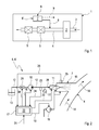
- a simplified illustrated motor vehicle 1 comprises an internal combustion engine 2, which receives fresh air via a fresh air system 3 and 4 exhaust combustion gases dissipates.
- exhaust purification devices 5 such. Ex. Catalysts and particulate filter can be arranged.
- the vehicle 1 is also equipped with a vehicle burner 6, with the aid of which a gas flow in the vehicle 1 can be heated.
- the vehicle burner 6 converts liquid fuel into a combustion chamber 7 with air.
- the combustion chamber 7 is connected to the exhaust system 4 on the exhaust side in accordance with an arrow 8 drawn by a solid line.
- the hot burner exhaust gases of the combustion chamber 7 of the exhaust system 4 can be supplied.
- the supply of these hot burner exhaust gases takes place within the exhaust system 4 with respect to a guided in the exhaust line 4 exhaust flow upstream of at least one heated by means of the vehicle's burner 6 exhaust gas purification device 5.
- a heating at least one exhaust gas purification device 5 are realized to an operating temperature, so that the respective exhaust gas cleaning device 5 can fulfill their cleaning function effectively.
- many catalysts have a light-off temperature from which they can develop their catalytic cleaning action.
- the vehicle burner 6 can be designed as a heating device 6 ', which can be operated independently of the internal combustion engine 2.
- Such a heater 6 ' may, for example.
- the burner exhaust gases generated in the combustion chamber 7 can then be used in accordance with an arrow 9 drawn with a broken line for heating a vehicle interior or for heating the internal combustion engine 2.
- the vehicle burner 6 (the following explanations also apply correspondingly to the heating device 6 ') comprises a fuel pump 10 with the aid of which a fuel can be conveyed to an actuatable injection nozzle 11, which can also be referred to as an injector 11.
- a fuel line 12 connects a fuel tank 13 with the suction side of the fuel pump 10 and the pressure side of the fuel pump 10 with the injection nozzle 11.
- the injection nozzle 11 serves to inject the fuel into the combustion chamber 7, which in the example of Fig. 2 exhaust side or outlet side is connected to the exhaust system 4.
- An exhaust gas flow flowing in the exhaust system 4 is in Fig. 2 indicated by arrows 14.
- Fig. 2 indicated by arrows 14.
- the vehicle burner 6 also comprises an air-conveying and / or air-regulating device 16, which may, for example, also be a pump or a fan. Likewise, it may be a compressed air reservoir or another air source.
- the combustion chamber 7 may be connected via a suitable valve device to an air control device of a compressed air system of the respective vehicle, for example an air suspension device or an air pressure brake system, or an exhaust gas turbocharger. With her, air, z. Ex. From the environment, are promoted to the combustion chamber 7. Furthermore, the vehicle burner 6, a controller 17, with the aid of the vehicle's burner 6 can be operated.
- the Controller 17 includes at least one, not shown here processor and is configured to determine a function of a supplied via a signal line 21, predetermined heating power, a fuel amount that is required to realize this heating power.
- the heating power may, for example, be predetermined by a control unit of the internal combustion engine 2 or by a request of a user.
- the controller can now determine a quantity of air that is required, in the combustion chamber 7 in conjunction with the determined amount of fuel, a fuel-air mixture depending on the determined fuel quantity and in dependence on an air ratio, which can also be specified or already fixed to produce that has the desired air ratio. Furthermore, the controller 17 is designed such that it determines a fuel pressure as a function of the determined air quantity.
- the fuel pressure has a significant influence on various injection parameters, such. For example, droplet size, droplet velocity, injection angle and the like.
- the determination of the fuel pressure is carried out specifically so that optimized injection parameters are achieved for the respective amount of air, which leads to a certain air velocity in an invariant geometry of the combustion chamber 7.
- the controller 17 may first determine a resulting air velocity depending on the amount of air and then determine the optimal injection pressure depending on the air speed.
- Said map 22 can basically be arbitrarily complex. In particular, depending on the heating power, it can supply the fuel quantity and / or the air quantity and / or the airspeed and / or the air ratio and / or the fuel pressure.
- the controller 17 is now configured such that it adjusts the predetermined heating power by the air conveying and / or air control device 16 for setting the determined air quantity, the fuel pump 10 for setting the determined fuel pressure and the injection nozzle 11 is actuated to set the determined amount of fuel.
- the injection nozzle 11 is opened more or less as a function of the fuel pressure or clocked in terms of opening duration and opening frequency.
- the vehicle burner 6 shown here also has at least one pressure sensor 23, which is coupled to the controller 17 via a signal line 24.
- the pressure sensor 23 can be arranged directly on the fuel line 12 or on the output side of the fuel pump 10 or on the input side of the injection nozzle 11 ,
- the controller 17 can now for adjusting the determined fuel pressure, which forms a target fuel pressure, the measured by means of the pressure sensor 23 fuel pressure, which forms an actual fuel pressure compare with the target fuel pressure to the function of the difference, the fuel pump 10th to regulate.
- the controller 17 controls the fuel pump 10 in response to a target-actual comparison of the fuel pressure.
- a proportional control may be appropriate.
- a PID control algorithm or another control algorithm may be used.
- the aim of the control is the realization of the lowest possible pressure fluctuations in the fuel line 12th
- the vehicle's burner 6 may be equipped with at least one temperature sensor 25, which is coupled to the controller 17 via a signal line 26.
- the temperature sensor 25 is for measuring a combustion chamber temperature provided.
- the temperature sensor 25 measures the temperature of a wall of the combustion chamber 7.
- the temperature sensor 25 can measure the temperature of the burner exhaust gases.
- the controller 17 can now take into account the current combustion chamber temperature in determining the required fuel pressure. This consideration can already be stored in the map 22. By taking into account the combustion chamber temperature, for example, the droplet size can be varied to optimize the evaporation of the injected fuel.
- the ambient temperature and / or fuel temperature can be taken into account in order, for example, to compensate for differences in viscosity via a suitably adapted fuel pressure.
- the droplet size correlates with the fuel pressure, whereby this correlation between droplet size and fuel pressure is taken into account when taking into account the combustion chamber temperature.
- the controller 17 may vary the delivery rate of the fuel pump 10 to adjust the desired fuel pressure.
- the fuel pump 10 may, for example, be configured as a rotary pump, z. Ex. In the form of a centrifugal pump or a gear pump or a rotary vane pump or the like. The controller 17 may change the speed in such a rotary pump to adjust the respective delivery rate and thus the fuel pressure.
- the fuel pump 10 may be configured as an oscillation pump, such as. For example, a piston pump or a diaphragm pump or the like. In such an oscillation pump, the controller may vary the stroke frequency and / or the stroke length and / or the stroke speed in order to set the respective desired delivery rate and thus the fuel pressure.
- the respective fuel pump 10 may have an adjustable by means of the controller 17 throttle and a bypass. The fuel pump 10 then operates stationary and By varying the throttle, the output side pressure can be adjusted. Unnecessary fuel flows back into the tank via the bypass or internally back to the suction side.
- a pressure accumulator 27 may be connected, whereby it is possible to compensate for pressure fluctuations in the fuel-carrying system or to dampen.
- the fuel line 12 is designed as an accumulator 28 at least in a section leading from the fuel pump 10 to the injection nozzle 11 is particularly advantageous.
- said line section 28 has a comparatively large volume.
- the controller 17 may be configured to take into account a compressive elasticity of the fuel system when adjusting the fuel pressure.
- Said fuel system extends from the fuel pump 10 to the injection nozzle 11 and thus comprises at least the associated portion of the fuel line 12 and in particular the pressure accumulator 27 and 28 respectively.
- the vehicle burner 6 is also equipped with a locking device 29, which may be, for example, a valve, in particular a solenoid valve.
- the blocking device 29 is coupled to the controller 17 via a control line 30. It is arranged in the fuel line 12 and that expedient upstream of the fuel pump 10. It is arranged as close to the fuel tank 13.
- the controller 17 actuates the locking device 29 when turning off the vehicle's burner 6 to block the fuel line 12. As a result, the fuel line 12 is locked when the vehicle's burner 6 is turned off.
- the fuel pump 10 may have a blocking function depending on their construction, so that it is possible to dispense with the additional locking device 29.
- the blocking function of the respective fuel pump 10 can be realized, for example, by a specific relative position of a delivery member of the fuel pump 10.
- the lock function When the lock function is activated, the fuel pump 10 blocks the fuel line 12.
- the controller 17 can now press the fuel pump 10 to activate the lock function when switching off the vehicle's burner 6. As a result, the fuel line 12 is locked when the vehicle burner 6 is turned off.
- the pressure ranges in which the fuel pressures can be varied as a function of the heating power of the vehicle's burner 6 depend in particular on the fuel pump 10 and can, for example, be in the range of 1 bar to 10 bar inclusive. Preference is given to a pressure range of from 2 bar up to and including 8 bar. Particularly advantageous may be a pressure range of from 3 bar to 6 bar inclusive.
- the combustion chamber 7 may have a primary combustion zone 31 and a secondary combustion zone 32.
- the injection nozzle 11 is attached to the combustion chamber 7 so as to inject the fuel exclusively into the primary combustion zone 31.
- the combustion chamber 7 has a porous, flow-through structure 33, which separates the primary combustion zone 31 from the secondary combustion zone 32.
- the structure 33 ensures that no liquid fuel enters the secondary combustion zone 32. However, it is well intended that vaporous fuel passes through structure 33 into secondary combustion zone 32. In that regard, the conversion of the fuel in the combustion chamber 7 into a pre-oxidation, which takes place in the primary combustion zone 31, and a post-oxidation, which takes place in the secondary combustion zone 32.
- the structure 33 is here preferably configured conical.
- an igniter 34 may be provided, for. Eg a glow plug or a spark plug or a piezo igniter.
- An arrow 35 indicates the supply of the liquid fuel to the injection nozzle 11.
- the conveyed by the air conveyor 16 air is at the in Fig. 3 split combustion chamber 7 divided into primary air 36 and secondary air 37, which is indicated by corresponding arrows.
- the primary air 36 is thereby fed to the primary combustion zone 31, while the secondary air 37 is supplied to the secondary combustion zone 32.
- the primary air 36 can flow into the primary combustion zone 31, in particular coaxially with the injection jet.
- the combustion chamber 7 has an inner tube 38, in which the two combustion zones 31, 32 and the structure 33 are arranged. Furthermore, the combustion chamber 7 has an outer tube 39, which is arranged coaxially to the inner tube 38, this encloses and thereby forms an annular space 40. Through this annular space 40, the secondary air flows into the secondary combustion zone 32. In this case, the secondary air 37 flows through a wall of the inner tube 38, which has corresponding wall openings for this purpose.
- the combustion chamber 7, in particular the secondary combustion zone 32 is corresponding Fig. 3 on the exhaust side or on the outlet side again connected to the exhaust system 4, in which an exhaust gas flow 14 prevails during operation of the internal combustion engine 2. Although in Fig. 3 a vertical arrangement of combustion chamber 7 and exhaust system 4 is shown, other angles may be provided to reduce the flow resistance.
Landscapes
- Engineering & Computer Science (AREA)
- Chemical & Material Sciences (AREA)
- Combustion & Propulsion (AREA)
- Mechanical Engineering (AREA)
- General Engineering & Computer Science (AREA)
- Air-Conditioning For Vehicles (AREA)
Applications Claiming Priority (1)
| Application Number | Priority Date | Filing Date | Title |
|---|---|---|---|
| DE102008063990A DE102008063990A1 (de) | 2008-12-19 | 2008-12-19 | Fahrzeugbrenner |
Publications (3)
| Publication Number | Publication Date |
|---|---|
| EP2199678A2 true EP2199678A2 (fr) | 2010-06-23 |
| EP2199678A3 EP2199678A3 (fr) | 2011-12-14 |
| EP2199678B1 EP2199678B1 (fr) | 2016-10-19 |
Family
ID=42026180
Family Applications (1)
| Application Number | Title | Priority Date | Filing Date |
|---|---|---|---|
| EP09176832.5A Active EP2199678B1 (fr) | 2008-12-19 | 2009-11-24 | Brûleur pour dispositif de chauffage pour véhicule |
Country Status (4)
| Country | Link |
|---|---|
| US (1) | US8695569B2 (fr) |
| EP (1) | EP2199678B1 (fr) |
| CN (1) | CN101749728A (fr) |
| DE (1) | DE102008063990A1 (fr) |
Cited By (4)
| Publication number | Priority date | Publication date | Assignee | Title |
|---|---|---|---|---|
| DE102012110103A1 (de) * | 2012-10-23 | 2014-04-24 | Spheros Gmbh | Mit flüssigem Brennstoff betriebene Heizeinrichtung |
| RU203661U1 (ru) * | 2020-12-16 | 2021-04-15 | Публичное акционерное общество "КАМАЗ" | Система заправки топливного бака предпускового подогревателя |
| EP4202193A1 (fr) * | 2021-12-21 | 2023-06-28 | Marelli Europe S.p.A. | Dispositif de chauffage pour un système d'échappement d'un moteur à combustion interne et procédé de commande associé |
| WO2023237294A1 (fr) * | 2022-06-08 | 2023-12-14 | Robert Bosch Gmbh | Brûleur pour système de post-traitement des gaz d'échappement, système de post-traitement des gaz d'échappement pour un moteur à combustion interne |
Families Citing this family (28)
| Publication number | Priority date | Publication date | Assignee | Title |
|---|---|---|---|---|
| FR2946098A1 (fr) * | 2009-05-26 | 2010-12-03 | Patrick Wathieu | Procede de fonctionnement d'un moteur a explosion et moteur a explosion fonctionnant selon ce procede. |
| DE102010038865A1 (de) * | 2010-08-04 | 2012-02-09 | Robert Bosch Gmbh | Brenner mit stabiler Zerstäubung bei geringem Gegendruck |
| DE102011081309B3 (de) * | 2011-08-22 | 2012-09-27 | Bosch Emission Systems Gmbh & Co. Kg | Betriebsverfahren und Abgasanlage |
| ITBO20120128A1 (it) * | 2012-03-13 | 2013-09-14 | Riello Spa | Apparecchiatura di combustione di combustibili liquidi e relativo metodo per modulare la potenza di tale apparecchiatura |
| EP2789915A1 (fr) * | 2013-04-10 | 2014-10-15 | Alstom Technology Ltd | Procédé de fonctionnement d'une chambre de combustion et chambre de combustion |
| CN103675215B (zh) * | 2013-12-24 | 2016-01-20 | 安徽省芜湖仪器仪表研究有限责任公司 | 一种车用氧传感器的检测仿真系统 |
| DE102015220408A1 (de) * | 2015-10-20 | 2017-04-20 | Robert Bosch Gmbh | Verfahren und Vorrichtung zur Beheizung eines Katalysators |
| CN105485680B (zh) * | 2015-12-07 | 2018-11-20 | 湖南三一路面机械有限公司 | 燃烧器及其控制方法和沥青搅拌站 |
| RU2642863C2 (ru) * | 2016-07-08 | 2018-01-29 | Евгений Поликарпович Лебедев | Способ подготовки жидкого топлива к сжиганию и устройство для его реализации |
| RU171963U1 (ru) * | 2016-12-01 | 2017-06-22 | Публичное акционерное общество "КАМАЗ" | Система топливопитания предпускового подогревателя |
| CN107023366A (zh) * | 2017-05-26 | 2017-08-08 | 凯龙高科技股份有限公司 | 一种用于非道路农机的燃烧器dpf再生控制与诊断系统 |
| CN107091135A (zh) * | 2017-05-26 | 2017-08-25 | 凯龙高科技股份有限公司 | 满足pm排放控制的柴油机预混合燃烧器后处理系统 |
| DE102017007681A1 (de) * | 2017-08-09 | 2019-02-14 | Robert Zink | Gasbrenner mit verbesserten Eigenschaften |
| CN107387288A (zh) * | 2017-09-04 | 2017-11-24 | 郑州振资汽车配件有限公司 | 驻车加热器 |
| CN108954318B (zh) * | 2018-08-29 | 2023-08-25 | 国电环境保护研究院有限公司 | 气体燃料轴向分级预混燃烧特性的分析系统和分析方法 |
| KR102613522B1 (ko) | 2019-02-18 | 2023-12-13 | 삼성전자주식회사 | 베젤 처짐 방지 구조를 포함하는 폴더블 전자 장치 |
| CN111043623B (zh) * | 2019-12-30 | 2021-07-30 | 哈尔滨工业大学 | 一种基于电场影响火焰根部的闭环负反馈调节避免燃烧室产生共振的方法 |
| CN112065538B (zh) * | 2020-09-16 | 2022-07-15 | 孙金辉 | 一种柴油机后处理系统的热管理装置 |
| EP4019748B1 (fr) * | 2020-12-23 | 2023-12-06 | Marelli Europe S.p.A. | Dispositif de chauffage d'un système d'échappement d'un moteur à combustion interne |
| DE102021103123A1 (de) | 2021-02-10 | 2022-08-11 | Volkswagen Aktiengesellschaft | Verfahren und Vorrichtung zur Ermöglichung einer Kaltabfahrt bei Fahrzeugen mit monovalenter gasförmiger Kraftstoffversorgung mittels einer mit druckbeaufschlagter Zuluft versorgten Zuheizvorrichtung |
| IT202100017255A1 (it) * | 2021-06-30 | 2022-12-30 | Marelli Europe Spa | Metodo di controllo di un bruciatore per un sistema di scarico di un motore a combustione interna |
| IT202100017258A1 (it) * | 2021-06-30 | 2022-12-30 | Marelli Europe Spa | Metodo di controllo di un bruciatore per un sistema di scarico di un motore a combustione interna |
| US11506136B1 (en) * | 2021-07-22 | 2022-11-22 | Tenneco Automotive Operating Company Inc. | Selective catalytic reduction catalyst pre-heating and exhaust burner air control |
| IT202100021665A1 (it) * | 2021-08-10 | 2023-02-10 | Marelli Europe Spa | Metodo di controllo di un sistema di post-trattamento dei gas di scarico per un impianto di scarico dei gas esausti di un motore a combustione interna |
| EP4159984B1 (fr) * | 2021-10-04 | 2025-03-19 | Volvo Truck Corporation | Système de post-traitement de gaz d'échappement pour convertir des émissions nox dans les gaz d'échappement d'un moteur |
| DE102022211127A1 (de) * | 2022-10-20 | 2024-04-25 | Robert Bosch Gesellschaft mit beschränkter Haftung | Verfahren, Recheneinheit und Computerprogramm zum Betreiben eines Bren-ners |
| IT202200024240A1 (it) * | 2022-11-24 | 2024-05-24 | Marelli Europe Spa | Dispositivo riscaldatore per un sistema di scarico di un motore a combustione interna |
| CN117515590A (zh) * | 2023-11-07 | 2024-02-06 | 中国北方车辆研究所 | 一种多模式车辆热电联供燃烧系统 |
Family Cites Families (42)
| Publication number | Priority date | Publication date | Assignee | Title |
|---|---|---|---|---|
| DE1074920B (de) * | 1955-07-07 | 1960-02-04 | Ing habil Fritz A F Schmidt Murnau Dr (Obb) | Verfahren und \ orrichtung zur Regelung von Gas turbmenbrennkammern mit unterteilter Verbrennung und mehreren Druckstufen |
| DE3311603C2 (de) * | 1983-03-30 | 1986-11-13 | Walter 8702 Leinach Lang | Verfahren zur Steuerung der Verbrennung von insbesondere Heizöl in einer Heizanlage sowie Brenner zur Durchführung des Verfahrens |
| DE3734197A1 (de) * | 1987-10-09 | 1989-04-20 | Bosch Gmbh Robert | Einrichtung zum entfernen von festkoerperpartikeln, insbesondere russteilchen, aus dem abgas einer brennkraftmaschine |
| DE4216523C2 (de) * | 1992-05-19 | 1997-01-23 | Webasto Thermosysteme Gmbh | Brenner für ein mit flüssigem Brennstoff betriebenes Heizgerät, insbesondere Fahrzeugzusatzheizgerät |
| US5253475A (en) * | 1992-06-22 | 1993-10-19 | General Motors Corporation | Combustion detection |
| US5284016A (en) * | 1992-08-28 | 1994-02-08 | General Motors Corporation | Exhaust gas burner reactor |
| US5320523A (en) * | 1992-08-28 | 1994-06-14 | General Motors Corporation | Burner for heating gas stream |
| US5277025A (en) * | 1992-08-31 | 1994-01-11 | General Motors Corporation | Exhaust burner control |
| US5339630A (en) * | 1992-08-28 | 1994-08-23 | General Motors Corporation | Exhaust burner catalyst preheater |
| US5419121A (en) * | 1993-04-16 | 1995-05-30 | Engelhard Corporation | Method and apparatus for reduction of pollutants emitted from automotive engines by flame incineration |
| JP3282944B2 (ja) * | 1994-07-18 | 2002-05-20 | トヨタ自動車株式会社 | 低NOxバーナ |
| DE4435196C1 (de) * | 1994-09-30 | 1995-10-12 | Siemens Ag | Verfahren zum Überprüfen eines Brennersystems zur Katalysatoraufheizung |
| DE4447286A1 (de) * | 1994-12-30 | 1996-07-04 | Eberspaecher J | Fahrzeugheizgerät mit geregeltem Verbrennungsluftgebläse |
| WO1997040315A1 (fr) * | 1996-04-20 | 1997-10-30 | Joh. Vaillant Gmbh U. Co. | BRULEUR ET PROCEDE DE FONCTIONNEMENT D'UN BRULEUR DESTINE A UNE COMBUSTION PAUVRE EN NOx ET EN CO |
| EP0979353B1 (fr) * | 1998-02-27 | 2004-09-29 | Stanadyne Corporation | Pompe d'alimentation pour rampe d'alimentation en essence |
| US6736635B1 (en) * | 1999-11-02 | 2004-05-18 | Ebara Corporation | Combustor for exhaust gas treatment |
| JP3920526B2 (ja) * | 2000-03-08 | 2007-05-30 | トヨタ自動車株式会社 | 火花点火式成層燃焼内燃機関 |
| DE10059427A1 (de) * | 2000-11-30 | 2002-06-06 | Bosch Gmbh Robert | Einrichtung und Verfahren zur Nachbehandlung von Abgasen |
| DE10105230A1 (de) * | 2001-02-02 | 2002-08-29 | Endress & Hauser Gmbh & Co Kg | Differenzdrucksensor mit Überlastsicherung |
| WO2002066809A2 (fr) * | 2001-02-02 | 2002-08-29 | Siemens Aktiengesellschaft | Detecteur place sur la conduite d'injection d'un moteur a combustion interne a injection directe, cette conduite aboutissant a une soupape d'injection |
| JP3899884B2 (ja) * | 2001-10-04 | 2007-03-28 | トヨタ自動車株式会社 | 内燃機関の排気浄化装置 |
| DE10151688A1 (de) * | 2001-10-19 | 2003-04-30 | Bosch Gmbh Robert | Ventil zum Steuern von Flüssigkeiten |
| DE10304489B4 (de) * | 2002-04-11 | 2014-07-31 | Das Environmental Expert Gmbh | Einrichtung zur Reinigung von Abgasen mit fluorhaltigen Verbindungen in einem Verbrennungsreaktor mit niedriger Stickoxidemission |
| DE10240208B4 (de) * | 2002-06-25 | 2004-12-09 | Webasto Ag | Heizgerät mit einem Detektor |
| DE10230401A1 (de) * | 2002-07-05 | 2004-01-22 | J. Eberspächer GmbH & Co. KG | Brennstoffdruckregler, insbesondere für einen Zerstäuberbrenner für ein Fahrzeugheizgerät |
| JP2004324587A (ja) * | 2003-04-25 | 2004-11-18 | Mitsubishi Fuso Truck & Bus Corp | 内燃機関の排気浄化装置 |
| JP3960283B2 (ja) * | 2003-09-01 | 2007-08-15 | トヨタ自動車株式会社 | 内燃機関の燃料噴射装置 |
| DE10354232A1 (de) * | 2003-11-20 | 2005-06-30 | J. Eberspächer GmbH & Co. KG | Abgasbehandlungssystem für eine Brennkraftmaschine, insbesondere Diesel-Brennkraftmaschine, und Verfahren zum Betreiben eines Abgasbehandlungssystems für eine Brennkraftmaschine |
| JP2005273577A (ja) * | 2004-03-25 | 2005-10-06 | Nissan Diesel Motor Co Ltd | 液化ガス燃料供給装置 |
| DE102004020507A1 (de) * | 2004-04-26 | 2005-11-24 | J. Eberspächer GmbH & Co. KG | Verdampferanordnung zur Erzeugung eines Kohlenwasserstoffdampf/Mischmaterial-Gemisches, insbesondere für eine Reformeranordnung eines Brennstoffzellensystems |
| DE102004061400B4 (de) * | 2004-12-21 | 2012-12-20 | Umicore Ag & Co. Kg | Verfahren zur Erzeugung eines Stromes heißer Verbrennungsabgase mit einstellbarer Temperatur, Apparatur zur Durchführung des Verfahrens und Verwendung der Verbrennungsabgase zur gezielten Alterung von Katalysatoren |
| KR100542803B1 (ko) * | 2005-06-22 | 2006-01-11 | 한국기계연구원 | 디젤엔진매연여과장치 재생용 버너 |
| US7503168B2 (en) * | 2006-03-24 | 2009-03-17 | Cumming Filtration Ip, Inc | Apparatus, system, and method for particulate filter regeneration |
| US7552584B2 (en) * | 2006-03-31 | 2009-06-30 | Caterpillar Inc. | Common engine and exhaust treatment fuel system |
| DE102006050560A1 (de) * | 2006-06-03 | 2007-12-06 | Bayerische Motoren Werke Ag | Betriebsverfahren für ein System aus einem Reformer und einer katalytischen Abgas-Nachbehandlungsvorrichtung |
| US7849682B2 (en) * | 2006-08-31 | 2010-12-14 | Caterpillar Inc | Exhaust treatment device having a fuel powered burner |
| DE102006060299A1 (de) * | 2006-12-20 | 2008-06-26 | Robert Bosch Gmbh | Verfahren zum Betreiben eines Kraftstoffsystems für eine Brennkraftmaschine |
| AT504523B1 (de) * | 2007-01-04 | 2008-06-15 | Glueck Christoph Ing | Verfahren zum verfeuern von flüssigen brennstoffen |
| JP4951380B2 (ja) * | 2007-03-26 | 2012-06-13 | 日立オートモティブシステムズ株式会社 | 高圧燃料系の制御装置 |
| US7591648B2 (en) * | 2007-09-13 | 2009-09-22 | Maxon Corporation | Burner apparatus |
| US20120073268A1 (en) * | 2010-09-29 | 2012-03-29 | Navin Khadiya | Fuel-fired burner for no2 based regeneration |
| US8438838B2 (en) * | 2010-10-11 | 2013-05-14 | Faurecia Emissions Control Technologies | Fuel-fired burner and heat exchanger system for heating a NOx reducing agent supply tank |
-
2008
- 2008-12-19 DE DE102008063990A patent/DE102008063990A1/de not_active Ceased
-
2009
- 2009-11-24 EP EP09176832.5A patent/EP2199678B1/fr active Active
- 2009-12-17 US US12/640,483 patent/US8695569B2/en active Active
- 2009-12-21 CN CN200910247076A patent/CN101749728A/zh active Pending
Cited By (5)
| Publication number | Priority date | Publication date | Assignee | Title |
|---|---|---|---|---|
| DE102012110103A1 (de) * | 2012-10-23 | 2014-04-24 | Spheros Gmbh | Mit flüssigem Brennstoff betriebene Heizeinrichtung |
| WO2014063845A1 (fr) * | 2012-10-23 | 2014-05-01 | Spheros Gmbh | Système de chauffage fonctionnant avec un combustible liquide |
| RU203661U1 (ru) * | 2020-12-16 | 2021-04-15 | Публичное акционерное общество "КАМАЗ" | Система заправки топливного бака предпускового подогревателя |
| EP4202193A1 (fr) * | 2021-12-21 | 2023-06-28 | Marelli Europe S.p.A. | Dispositif de chauffage pour un système d'échappement d'un moteur à combustion interne et procédé de commande associé |
| WO2023237294A1 (fr) * | 2022-06-08 | 2023-12-14 | Robert Bosch Gmbh | Brûleur pour système de post-traitement des gaz d'échappement, système de post-traitement des gaz d'échappement pour un moteur à combustion interne |
Also Published As
| Publication number | Publication date |
|---|---|
| EP2199678B1 (fr) | 2016-10-19 |
| DE102008063990A1 (de) | 2010-06-24 |
| US8695569B2 (en) | 2014-04-15 |
| CN101749728A (zh) | 2010-06-23 |
| EP2199678A3 (fr) | 2011-12-14 |
| US20100154745A1 (en) | 2010-06-24 |
Similar Documents
| Publication | Publication Date | Title |
|---|---|---|
| EP2199678B1 (fr) | Brûleur pour dispositif de chauffage pour véhicule | |
| EP0599060B1 (fr) | Brûleur de dépollution ou de purification d'un moteur à combustion interne | |
| DE112007002006B4 (de) | Abgasaufbereitungsvorrichtung mit einem kraftstoffbetriebenen Brenner | |
| DE1933514A1 (de) | Brennstoffeinspritzsystem fuer Brennkraftmaschinen | |
| DE102005054733A1 (de) | Brenner zur Katalysatoraufheizung mit gesteuerter oder geregelter Kraftstoffzuführung | |
| EP1582709B1 (fr) | Méthode de régénération d'un filtre à particule ainsi qu'un système d'échappement avec un filtre à particule | |
| EP3408528B1 (fr) | Système d'émulsification et procédé d'émulsification | |
| WO2014131498A1 (fr) | Procédé et dispositif pour faire fonctionner un moteur diesel avec des carburants émulsifiés de composition variable | |
| EP0599061B1 (fr) | Méthode de purification de gaz d'échappement d'un moteur à combustion interne | |
| EP1969211A1 (fr) | Installation de gaz d'echappement de vehicule a moteur et procede pour regenerer un filtre a particules dans une installation de gaz d'echappement de vehicule a moteur | |
| EP1752632B1 (fr) | Dispositif de purification de gaz d'échappement et méthode correspondante | |
| DE4411959A1 (de) | Vorrichtung und Verfahren zur Vorwärmung der Ansaugluft einer Diesel-Brennkraftmaschine | |
| EP0816673B1 (fr) | Procédé de commande d'une installation de démarrage par flamme pour moteur à combustion interne et installation de démarrage par flamme pour moteur à combustion interne | |
| DE102004062208A1 (de) | Abgasanlage für ein Kraftfahrzeug mit wenigstens einem Abgasreinigungssystem und Verfahren zur Regeneration eines solchen | |
| DE102009026266A1 (de) | Mobiles Heizgerät | |
| DE102008024470B4 (de) | Verfahren zum Regenerieren eines Abgasreinigungsfilters sowie Verdampfer | |
| EP3530504B1 (fr) | Procédé de fonctionnement d'un appareil de chauffage à combustible pour véhicule | |
| DE4416014A1 (de) | Verfahren und Vorrichtung zur Verbesserung der Reinigung des Abgases eines Verbrennungsmotors mit einer Abgasreinigungsanlage, insbesondere in einem Kraftfahrzeug | |
| DE102013111546B9 (de) | Verfahren zum Einstellen eines mobilen, brennstoffbetriebenen Heizgeräts | |
| EP4056896A1 (fr) | Système de brûleur pour préchauffer un système de nettoyage des gaz d'échappement | |
| EP2659122A1 (fr) | Procédé de commande de mesures de chauffage de catalyseur dans un moteur à combustion interne comprenant deux injecteurs par cylindre | |
| DE102011052324A1 (de) | Fahrzeugheizgerät zum Betrieb mit mehreren Brennstoffarten | |
| DE10228004A1 (de) | Verfahren zur Bestimmung einer Beladung eines Aktivkohlebehälters eines Tankentlüftungssystems | |
| DE102015200462A1 (de) | Abgasnachbehandlungssystem | |
| WO2012016817A1 (fr) | Brûleur à pulvérisation stable en cas de faible contre-pression |
Legal Events
| Date | Code | Title | Description |
|---|---|---|---|
| PUAI | Public reference made under article 153(3) epc to a published international application that has entered the european phase |
Free format text: ORIGINAL CODE: 0009012 |
|
| AK | Designated contracting states |
Kind code of ref document: A2 Designated state(s): AT BE BG CH CY CZ DE DK EE ES FI FR GB GR HR HU IE IS IT LI LT LU LV MC MK MT NL NO PL PT RO SE SI SK SM TR |
|
| PUAL | Search report despatched |
Free format text: ORIGINAL CODE: 0009013 |
|
| AK | Designated contracting states |
Kind code of ref document: A3 Designated state(s): AT BE BG CH CY CZ DE DK EE ES FI FR GB GR HR HU IE IS IT LI LT LU LV MC MK MT NL NO PL PT RO SE SI SK SM TR |
|
| RIC1 | Information provided on ipc code assigned before grant |
Ipc: F23D 99/00 20100101ALI20111110BHEP Ipc: F23D 11/24 20060101ALI20111110BHEP Ipc: F23N 1/02 20060101AFI20111110BHEP Ipc: F23K 5/04 20060101ALI20111110BHEP |
|
| 17P | Request for examination filed |
Effective date: 20120613 |
|
| RAP1 | Party data changed (applicant data changed or rights of an application transferred) |
Owner name: BOSCH EMISSION SYSTEMS GMBH & CO. KG |
|
| RAP1 | Party data changed (applicant data changed or rights of an application transferred) |
Owner name: ROBERT BOSCH GMBH |
|
| REG | Reference to a national code |
Ref country code: DE Ref legal event code: R079 Ref document number: 502009013244 Country of ref document: DE Free format text: PREVIOUS MAIN CLASS: F23N0001020000 Ipc: F01N0009000000 |
|
| RIC1 | Information provided on ipc code assigned before grant |
Ipc: F23K 5/04 20060101ALI20160511BHEP Ipc: F23D 11/24 20060101ALI20160511BHEP Ipc: F23N 1/02 20060101ALI20160511BHEP Ipc: F23D 99/00 20100101ALI20160511BHEP Ipc: F01N 9/00 20060101AFI20160511BHEP |
|
| GRAP | Despatch of communication of intention to grant a patent |
Free format text: ORIGINAL CODE: EPIDOSNIGR1 |
|
| INTG | Intention to grant announced |
Effective date: 20160718 |
|
| GRAS | Grant fee paid |
Free format text: ORIGINAL CODE: EPIDOSNIGR3 |
|
| GRAA | (expected) grant |
Free format text: ORIGINAL CODE: 0009210 |
|
| AK | Designated contracting states |
Kind code of ref document: B1 Designated state(s): AT BE BG CH CY CZ DE DK EE ES FI FR GB GR HR HU IE IS IT LI LT LU LV MC MK MT NL NO PL PT RO SE SI SK SM TR |
|
| REG | Reference to a national code |
Ref country code: GB Ref legal event code: FG4D Free format text: NOT ENGLISH |
|
| REG | Reference to a national code |
Ref country code: CH Ref legal event code: EP |
|
| REG | Reference to a national code |
Ref country code: AT Ref legal event code: REF Ref document number: 838554 Country of ref document: AT Kind code of ref document: T Effective date: 20161115 |
|
| REG | Reference to a national code |
Ref country code: IE Ref legal event code: FG4D Free format text: LANGUAGE OF EP DOCUMENT: GERMAN |
|
| REG | Reference to a national code |
Ref country code: FR Ref legal event code: PLFP Year of fee payment: 8 |
|
| REG | Reference to a national code |
Ref country code: DE Ref legal event code: R096 Ref document number: 502009013244 Country of ref document: DE |
|
| REG | Reference to a national code |
Ref country code: NL Ref legal event code: MP Effective date: 20161019 |
|
| REG | Reference to a national code |
Ref country code: LT Ref legal event code: MG4D |
|
| PG25 | Lapsed in a contracting state [announced via postgrant information from national office to epo] |
Ref country code: LV Free format text: LAPSE BECAUSE OF FAILURE TO SUBMIT A TRANSLATION OF THE DESCRIPTION OR TO PAY THE FEE WITHIN THE PRESCRIBED TIME-LIMIT Effective date: 20161019 Ref country code: BE Free format text: LAPSE BECAUSE OF NON-PAYMENT OF DUE FEES Effective date: 20161130 |
|
| PG25 | Lapsed in a contracting state [announced via postgrant information from national office to epo] |
Ref country code: SE Free format text: LAPSE BECAUSE OF FAILURE TO SUBMIT A TRANSLATION OF THE DESCRIPTION OR TO PAY THE FEE WITHIN THE PRESCRIBED TIME-LIMIT Effective date: 20161019 Ref country code: LT Free format text: LAPSE BECAUSE OF FAILURE TO SUBMIT A TRANSLATION OF THE DESCRIPTION OR TO PAY THE FEE WITHIN THE PRESCRIBED TIME-LIMIT Effective date: 20161019 Ref country code: NO Free format text: LAPSE BECAUSE OF FAILURE TO SUBMIT A TRANSLATION OF THE DESCRIPTION OR TO PAY THE FEE WITHIN THE PRESCRIBED TIME-LIMIT Effective date: 20170119 Ref country code: GR Free format text: LAPSE BECAUSE OF FAILURE TO SUBMIT A TRANSLATION OF THE DESCRIPTION OR TO PAY THE FEE WITHIN THE PRESCRIBED TIME-LIMIT Effective date: 20170120 |
|
| PG25 | Lapsed in a contracting state [announced via postgrant information from national office to epo] |
Ref country code: PL Free format text: LAPSE BECAUSE OF FAILURE TO SUBMIT A TRANSLATION OF THE DESCRIPTION OR TO PAY THE FEE WITHIN THE PRESCRIBED TIME-LIMIT Effective date: 20161019 Ref country code: PT Free format text: LAPSE BECAUSE OF FAILURE TO SUBMIT A TRANSLATION OF THE DESCRIPTION OR TO PAY THE FEE WITHIN THE PRESCRIBED TIME-LIMIT Effective date: 20170220 Ref country code: IS Free format text: LAPSE BECAUSE OF FAILURE TO SUBMIT A TRANSLATION OF THE DESCRIPTION OR TO PAY THE FEE WITHIN THE PRESCRIBED TIME-LIMIT Effective date: 20170219 Ref country code: FI Free format text: LAPSE BECAUSE OF FAILURE TO SUBMIT A TRANSLATION OF THE DESCRIPTION OR TO PAY THE FEE WITHIN THE PRESCRIBED TIME-LIMIT Effective date: 20161019 Ref country code: NL Free format text: LAPSE BECAUSE OF FAILURE TO SUBMIT A TRANSLATION OF THE DESCRIPTION OR TO PAY THE FEE WITHIN THE PRESCRIBED TIME-LIMIT Effective date: 20161019 Ref country code: ES Free format text: LAPSE BECAUSE OF FAILURE TO SUBMIT A TRANSLATION OF THE DESCRIPTION OR TO PAY THE FEE WITHIN THE PRESCRIBED TIME-LIMIT Effective date: 20161019 Ref country code: HR Free format text: LAPSE BECAUSE OF FAILURE TO SUBMIT A TRANSLATION OF THE DESCRIPTION OR TO PAY THE FEE WITHIN THE PRESCRIBED TIME-LIMIT Effective date: 20161019 |
|
| REG | Reference to a national code |
Ref country code: CH Ref legal event code: PL |
|
| REG | Reference to a national code |
Ref country code: DE Ref legal event code: R097 Ref document number: 502009013244 Country of ref document: DE |
|
| PG25 | Lapsed in a contracting state [announced via postgrant information from national office to epo] |
Ref country code: EE Free format text: LAPSE BECAUSE OF FAILURE TO SUBMIT A TRANSLATION OF THE DESCRIPTION OR TO PAY THE FEE WITHIN THE PRESCRIBED TIME-LIMIT Effective date: 20161019 Ref country code: MC Free format text: LAPSE BECAUSE OF FAILURE TO SUBMIT A TRANSLATION OF THE DESCRIPTION OR TO PAY THE FEE WITHIN THE PRESCRIBED TIME-LIMIT Effective date: 20161019 Ref country code: SK Free format text: LAPSE BECAUSE OF FAILURE TO SUBMIT A TRANSLATION OF THE DESCRIPTION OR TO PAY THE FEE WITHIN THE PRESCRIBED TIME-LIMIT Effective date: 20161019 Ref country code: CH Free format text: LAPSE BECAUSE OF NON-PAYMENT OF DUE FEES Effective date: 20161130 Ref country code: DK Free format text: LAPSE BECAUSE OF FAILURE TO SUBMIT A TRANSLATION OF THE DESCRIPTION OR TO PAY THE FEE WITHIN THE PRESCRIBED TIME-LIMIT Effective date: 20161019 Ref country code: RO Free format text: LAPSE BECAUSE OF FAILURE TO SUBMIT A TRANSLATION OF THE DESCRIPTION OR TO PAY THE FEE WITHIN THE PRESCRIBED TIME-LIMIT Effective date: 20161019 Ref country code: LI Free format text: LAPSE BECAUSE OF NON-PAYMENT OF DUE FEES Effective date: 20161130 Ref country code: CZ Free format text: LAPSE BECAUSE OF FAILURE TO SUBMIT A TRANSLATION OF THE DESCRIPTION OR TO PAY THE FEE WITHIN THE PRESCRIBED TIME-LIMIT Effective date: 20161019 |
|
| REG | Reference to a national code |
Ref country code: IE Ref legal event code: MM4A |
|
| PLBE | No opposition filed within time limit |
Free format text: ORIGINAL CODE: 0009261 |
|
| STAA | Information on the status of an ep patent application or granted ep patent |
Free format text: STATUS: NO OPPOSITION FILED WITHIN TIME LIMIT |
|
| PG25 | Lapsed in a contracting state [announced via postgrant information from national office to epo] |
Ref country code: IT Free format text: LAPSE BECAUSE OF FAILURE TO SUBMIT A TRANSLATION OF THE DESCRIPTION OR TO PAY THE FEE WITHIN THE PRESCRIBED TIME-LIMIT Effective date: 20161019 Ref country code: SM Free format text: LAPSE BECAUSE OF FAILURE TO SUBMIT A TRANSLATION OF THE DESCRIPTION OR TO PAY THE FEE WITHIN THE PRESCRIBED TIME-LIMIT Effective date: 20161019 Ref country code: BG Free format text: LAPSE BECAUSE OF FAILURE TO SUBMIT A TRANSLATION OF THE DESCRIPTION OR TO PAY THE FEE WITHIN THE PRESCRIBED TIME-LIMIT Effective date: 20170119 |
|
| 26N | No opposition filed |
Effective date: 20170720 |
|
| GBPC | Gb: european patent ceased through non-payment of renewal fee |
Effective date: 20170119 |
|
| PG25 | Lapsed in a contracting state [announced via postgrant information from national office to epo] |
Ref country code: LU Free format text: LAPSE BECAUSE OF NON-PAYMENT OF DUE FEES Effective date: 20161130 |
|
| REG | Reference to a national code |
Ref country code: FR Ref legal event code: PLFP Year of fee payment: 9 |
|
| PG25 | Lapsed in a contracting state [announced via postgrant information from national office to epo] |
Ref country code: IE Free format text: LAPSE BECAUSE OF NON-PAYMENT OF DUE FEES Effective date: 20161124 Ref country code: SI Free format text: LAPSE BECAUSE OF FAILURE TO SUBMIT A TRANSLATION OF THE DESCRIPTION OR TO PAY THE FEE WITHIN THE PRESCRIBED TIME-LIMIT Effective date: 20161019 Ref country code: GB Free format text: LAPSE BECAUSE OF NON-PAYMENT OF DUE FEES Effective date: 20170119 |
|
| REG | Reference to a national code |
Ref country code: AT Ref legal event code: MM01 Ref document number: 838554 Country of ref document: AT Kind code of ref document: T Effective date: 20161124 |
|
| PG25 | Lapsed in a contracting state [announced via postgrant information from national office to epo] |
Ref country code: AT Free format text: LAPSE BECAUSE OF NON-PAYMENT OF DUE FEES Effective date: 20161124 |
|
| REG | Reference to a national code |
Ref country code: BE Ref legal event code: MM Effective date: 20161130 |
|
| PG25 | Lapsed in a contracting state [announced via postgrant information from national office to epo] |
Ref country code: CY Free format text: LAPSE BECAUSE OF FAILURE TO SUBMIT A TRANSLATION OF THE DESCRIPTION OR TO PAY THE FEE WITHIN THE PRESCRIBED TIME-LIMIT Effective date: 20161019 Ref country code: HU Free format text: LAPSE BECAUSE OF FAILURE TO SUBMIT A TRANSLATION OF THE DESCRIPTION OR TO PAY THE FEE WITHIN THE PRESCRIBED TIME-LIMIT; INVALID AB INITIO Effective date: 20091124 |
|
| PG25 | Lapsed in a contracting state [announced via postgrant information from national office to epo] |
Ref country code: TR Free format text: LAPSE BECAUSE OF FAILURE TO SUBMIT A TRANSLATION OF THE DESCRIPTION OR TO PAY THE FEE WITHIN THE PRESCRIBED TIME-LIMIT Effective date: 20161019 Ref country code: MK Free format text: LAPSE BECAUSE OF FAILURE TO SUBMIT A TRANSLATION OF THE DESCRIPTION OR TO PAY THE FEE WITHIN THE PRESCRIBED TIME-LIMIT Effective date: 20161019 |
|
| PG25 | Lapsed in a contracting state [announced via postgrant information from national office to epo] |
Ref country code: MT Free format text: LAPSE BECAUSE OF FAILURE TO SUBMIT A TRANSLATION OF THE DESCRIPTION OR TO PAY THE FEE WITHIN THE PRESCRIBED TIME-LIMIT Effective date: 20161019 |
|
| REG | Reference to a national code |
Ref country code: DE Ref legal event code: R084 Ref document number: 502009013244 Country of ref document: DE |
|
| PGFP | Annual fee paid to national office [announced via postgrant information from national office to epo] |
Ref country code: FR Payment date: 20251125 Year of fee payment: 17 |
|
| PGFP | Annual fee paid to national office [announced via postgrant information from national office to epo] |
Ref country code: DE Payment date: 20260126 Year of fee payment: 17 |