EP2199811A1 - Appareil pour déterminer le taux d'absorption spécifique (SAR) d'un transmitteur, en particulier d'un téléphone portable, en faisant passer le transmitteur devant un Phantom solide, sec contenant un intensimètre noyé - Google Patents
Appareil pour déterminer le taux d'absorption spécifique (SAR) d'un transmitteur, en particulier d'un téléphone portable, en faisant passer le transmitteur devant un Phantom solide, sec contenant un intensimètre noyé Download PDFInfo
- Publication number
- EP2199811A1 EP2199811A1 EP10156892A EP10156892A EP2199811A1 EP 2199811 A1 EP2199811 A1 EP 2199811A1 EP 10156892 A EP10156892 A EP 10156892A EP 10156892 A EP10156892 A EP 10156892A EP 2199811 A1 EP2199811 A1 EP 2199811A1
- Authority
- EP
- European Patent Office
- Prior art keywords
- phantom
- radio transmitter
- electromagnetic field
- absorbed power
- belt conveyor
- Prior art date
- Legal status (The legal status is an assumption and is not a legal conclusion. Google has not performed a legal analysis and makes no representation as to the accuracy of the status listed.)
- Granted
Links
Images






Classifications
-
- G—PHYSICS
- G01—MEASURING; TESTING
- G01R—MEASURING ELECTRIC VARIABLES; MEASURING MAGNETIC VARIABLES
- G01R29/00—Arrangements for measuring or indicating electric quantities not covered by groups G01R19/00 - G01R27/00
- G01R29/08—Measuring electromagnetic field characteristics
Definitions
- the present invention relates to an apparatus which uses a phantom simulating the electromagnetic characteristics of a human body to measure the amount of absorption by the human body of a radio wave or waves radiated from a radio transmitter which is operated in the vicinity of the body through a relative scan of the phantom and the radio transmitter.
- the power absorbed by a human body for example, by the head of the human body, has been estimated by constructing a head simulation phantom which simulates the configuration and the electromagnetic characteristics of the head of the human body and measuring the amount of power absorbed by the phantom.
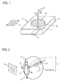
- a head simulation phantom 2 is constructed by forming a recess 12 configured to divide the head of the human body into two equal parts laterally in a top surface of a vessel 11 and filling the recess 12 with a liquid medium 10 which simulates the electromagnetic characteristics of the head.
- the liquid medium for a 900 MHz solution comprises 56.5% of sucrose, 40.92% of deionized water, 1.48% of sodium chloride, 1.0% of hydroxyl cellulose and 0.1% of bactericide as disclosed in a literature IEC/PT62209, "Procedure to Determine the Specific Absorption Rate (SAR) for Hand-held Mobile Telephones" or the like.
- a radio transmitter 3 which represents a radio wave radiation source is secured to the bottom surface of the vessel 11 on the outside thereof at a location central of the vessel 11 or which corresponds to the ear of the head of the human body.
- An electromagnetic field probe 1 which detects an electric or a magnetic field is inserted into the liquid medium 10 and is scanned in a plane which opposes the radio transmitter 3.
- the head simulation phantom 2 and the radio transmitter 3 are separately secured and only the electromagnetic field probe 1 is moved as indicated by arrows 8 for purpose of scan.
- a resulting detected value of the electromagnetic field probe 1 is squared, and the squared value is multiplied by a calibration factor to determine the absorbed power which occurs within the head simulation phantom 2.
- Broken lines 6, shown laterally offset, represent the locus of scan of the probe 1, and this corresponds to the measurement of absorbed power from the radio wave in a situation that the mobile telephone is located close to the ear of the head of the human body during the transmission and reception with the antenna (not shown) of the radio transmitter 3 extending in a direction through the casing of the radio transmitter 3 which runs substantially parallel to the bottom surface of the vessel 11.
- the head simulation phantom 2 shown in Fig. 1 is filled with the liquid medium 10, and is inconvenient in its handling. Since the probe 1 is moved within the liquid medium 10 for purpose of scan and measurement, the liquid medium 10 remains open to the air, and there arises a problem that the liquid medium 10 may be evaporated to cause an aging effect of the electromagnetic characteristics thereof.
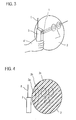
- FIG. 2 A head simulation phantom 2 which simulates the configuration and the electromagnetic characteristics of the head of the human body is constructed, and an electromagnetic field probe 1 is inserted into an opening 21 formed in the phantom 2.
- the electromagnetic field probe 1 is located close to the ear of the head simulation phantom 2, while a radio transmitter 3 which represents a radio wave radiation source is positioned on the external surface of the head simulation phantom 2 close to the ear.
- the transmitter 3 is moved vertically and back-and-forth, as indicated by arrows 8, for purpose of two-dimensional scan while deriving a detected value from the electromagnetic probe 1 , and multiplying a calibration factor to the square of the detected value to determine the absorbed power.
- the locus of scan for this case is illustrated by broken line 6, shown laterally offset. It is assumed in Fig. 2 that a mobile telephone is used as the radio transmitter 3 with an antenna extended from the telephone case to simulate the manner of use of a mobile telephone.
- the phantom 2 shown in Fig. 2 simulates the head of the human body by a spherical solid dielectric 10' or by a liquid dielectric (liquid medium) 10 which fills the interior of a spherical vessel.
- the head phantom2 is formed with a size simulating the head of the human body, or with a sphere having a diameter of 200mm, it contains a volume of 4 ⁇ (200/2)mm ⁇ 3 /3.
- the dielectric which simulates the electromagnetic characteristics of the head of the human body has a density which is equal to about 0.002g/mm 3 for the solid dielectric 10' and which is equal to about 0.001g/m 3 for the liquid dielectric (liquid medium).
- the head simulation phantom 2 has a weight which is equal to the volume 4 ⁇ (200/2)mm ⁇ 3 /3 multiplied by the density 0.002g/mm 3 or 8400g for the solid dielectric 10'.
- a conventional head simulation phantom 2 has a weight which is as high as 4200g or 8400g, and presented an inconvenience in its handling and transportation.
- the purpose of measuring the absorbed power is to know how much of a radio wave is absorbed by the human body during the use of a mobile telephone or a transceiver, and the measurement takes place in a so-called near field in which a distance from a radio wave radiation source to the phantom 2 is normally very small.
- a distance from a radio wave radiation source to the phantom 2 is normally very small.
- the reproducibility of positional relationship between the radio transmitter 3, the head simulation phantom 2 and the electromagnetic field probe 1 has upon the reproducibility of results of measurement.
- there is a relatively small shift in the relationship there occurs a change in the reflection characteristic of the phantom 2, producing a change in the distribution of the radiated electromagnetic field.
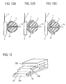
- the radio transmitter 3 is held by the hand 4' of a measuring personnel as indicated in Fig. 3 , it is difficult to maintain a correct position of the transmitter relative to the phantom 2, and a good reproducibility of measured values cannot be guaranteed. There also occur influences that the radio wave radiated from the radio transmitter 3 is absorbed by the hand 4' of the measuring person and that the current distribution on the antenna 5 of the radio transmitter 3 may be changed due to the hand 4' of the measuring personnel. Where the radio transmitter has a bulky volume or heavy, it may be difficult to conduct a spatial scan of the radio transmitter 3 relative to the phantom 2 by hand 4'.
- the radio transmitter 3 is fixed while the absorbed power measuring assembly 7 comprising the head simulation phantom 2 and the electromagnetic field probe 1 scans through a two-dimensional movement relative to the radio transmitter 3, it is a troublesome operation to perform the measurement by manually moving and scanning the absorbed power measuring assembly 7 when the head simulation phantom 2 has a weight which is as high as 4200g or 8400g as described above.
- an apparatus for measuring absorbed power in which an electromagnetic field probe is inserted inside a phantom which simulates the electromagnetic characteristics of a human body, the field strength of an electric field or a magnetic field of a radio wave which is externally irradiated upon the phantom is measured by the electromagnetic field probe, and the power of the radio wave which is absorbed by the human body is estimated on the basis of measured values, there is provided a scan mechanism which performs a relative movement between the phantom and the radio transmitter.
- the head simulation phantom 2 which simulates the configuration and the electromagnetic characteristics of the head of the human body shown in Fig. 2 is irradiated with a radio wave in SHF band, which represents a transmission frequency of a mobile telephone, or with a radio wave of a higher frequency band
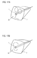
- the absorption of the power by the phantom 2 takes place in a manner indicated in Fig. 4 .
- the absorption will be greater in a surface layer 2a of the head simulation phantom 2 which is located close to the radio transmitter 3, but will be reduced in the inner thin layer 2b, and will be substantially equal to zero in the inside 2c.
- a half-wavelength dipole antenna when disposed at a distance of 10mm with respect to the phantom 2 having a diameter of 200mm, for example, and a radio wave (of frequency 900 MHz) is irradiated upon the phantom 2, it follows that denoting the absorption of the power of the radio wave which occurs at the surface of the phantom 2 by 1, the absorption at a point which is removed 20mm from the surface of the phantom will be reduced to 1/10, and will be reduced to 1/100 when removed 50mm. In this manner, most part of the phantom is not concerned with the measurement of absorbed power except for a very small portion which is located very close to the surface of the head simulation phantom 2.
- n advantage is taken of this by reducing the volume and the weight of the head simulation phantom 2. If there is a significant amount of absorption of the radio wave at a location disposed deep inside the phantom 2, a reduction in the volume of the phantom 2 will result in removing an internal portion where the absorption of the radio wave is occurring to prevent the measurement from the inner portion. However, such likelihood is eliminated since the absorption of the radio wave occurs only a portion thereof which is located close to the surface. It is to be noted that eyes and nose displayed in phantom lines in Fig. 4 merely indicate that this phantom simulates the head.
- a model is considered as illustrated in Fig. 5 .
- the phantom 2 is formed with a probe insertion opening 21 which extends from a point on the surface through the center to a point close to the opposite surface.
- the probe insertion opening 21 has a diameter of 10mm, and it is assumed that a distance from the inner end of the opening to the surface of the head simulation phantom 2 is equal to 10mm.
- a half-wavelength dipole antenna 5 is vertically disposed at a location which is spaced by 10mm from the surface of the head simulation phantom 2 which opposes the inner end of the probe insertion opening 21.
- the normalized power at the location where the electromagnetic field probe 1 is disposed or at the inner end 21 a of the probe insertion opening 21 can be calculated according to the finite-difference time-domain method (see, for example, " Finite Difference Time Domain Method for Electromagnetics," Karl S. Kung and Raymond J. Luebbers, CRC Press 1993 or the like). It is to be noted that the input power to the half-wavelength dipole antenna 5 is maintained constant, and the frequency of the radiated wave is 900 MHz.
- a curve which links ⁇ plots corresponds to a diameter D of the phantom 2 which is equal to 200mm (conventional one), a curve which links ⁇ plots corresponds to a diameter D equal to 1 00mm, and a curve which links 0 plots corresponds to D equal to 40mm.
- the weight of the head simulation phantom 2 which is on the order of 500g or 1000g means that a measuring personnel can easily handle the phantom 2 and move it for purpose of scan.
- the value of L increases to the order of 60mm
- the required range of measurement L is small, there is no problem.
- the range of measurement L increases, it is possible to reduce the weight and the cost required even though the accuracy of measurement is degraded. It is to be noted that with a phantom having a diameter D which is equal to or greater than 100mm, there is a less contribution to reducing the weight and the cost required even though a higher accuracy can be obtained.
- the volume of the phantom 2 is chosen to be equal to or less than 1/8 times the volume of part of the human body being simulated, or the volume of the normal head of the human body or 5 ⁇ 10 5 mm 3 . The less the volume of the phantom 2, the better in respect of reducing the weight, even though the accuracy of measurement becomes degraded as mentioned above.
- a minimum value for the volume of the phantom 2 may be chosen to be a volume which permits at least the probe 1 to be contained even though the accuracy of measurement may be degraded to a degree.
- a probe insertion opening 21 is formed extending from a point on the surface of the phantom 2 and extending to another point located close to the surface, and an electromagnetic field probe 1 is inserted into the probe insertion opening 21.
- an adhesive 14 is filled into the probe insertion opening 21, thus securing the electromagnetic field probe 1 within the phantom 2 to be integral therewith.
- a spacing D1 between the electromagnetic field probe 1 and the closest surface of the phantom 2 be preferably within 20mm, in particular, within 10mm in order to achieve a certain accuracy of measurement. While it is preferred to have a smaller value for D1, a suitable value is chosen in consideration of the ease of manufacture and a resistance to fracturing.
- a lead wire 1 a of the probe 1 is connected to a calculation and display unit 80 in the similar manner as a conventional apparatus of this kind, and the calculation and display unit 80 calculates and displays the absorbed power using the values detected by the probe 1 and using the absorption effect.
- a head simulation phantom 2 may be constructed using a confined vessel 11 which simulates the configuration of the head and a liquid medium 10 which fills the vessel 11.
- the liquid medium 10 may be similar to that mentioned previously in connection with Fig. 1 .
- the volume of the phantom 2 is again chosen to be equal to or less than 1/8 times the volume of the normal head of the human body or 5 ⁇ 10 5 mm 3 .
- the confined vessel 11 is formed with a probe insertion opening 21 in the similar manner as in Fig. 7 , into which an electromagnetic field probe 1 is inserted and may be secured by using an adhesive 14, for example, to be integral with the phantom 2.
- the vessel 11 is formed of a material such as acrylic resin or Teflon (registered trademark) having a low dielectric constant which is close to that of the air preferably, thus preventing the distribution of a radio wave radiated from a radio transmitter 3 (not shown) from being disturbed.
- a material such as acrylic resin or Teflon (registered trademark) having a low dielectric constant which is close to that of the air preferably, thus preventing the distribution of a radio wave radiated from a radio transmitter 3 (not shown) from being disturbed.
- Figs. 7A and 7B in order to connect the electromagnetic field probe 1 to be integral with the phantom 2, other techniques than filling the adhesive 14 into the probe insertion opening 21 may be used to secure them together.
- the spherical head simulation phantom 2 shown in Figs. 7A and 7B has its volume reduced to or less than 5 ⁇ 10 5 mm 3 which corresponds to 1/8 times the volume of the conventional phantom which represents the size of the head of the human body, and the weight is reduced to or less than 1/8 times the weight of the conventional phantom, and thus is greatly reduced in weight.
- the weight will be equal to or less than 500g when the liquid medium 10 is used, and will be equal to or less than 1000g when the solid dielectric 10' is used. Accordingly, while the radio transmitter 3 is retained by and fixed on a retainer 4 as illustrated in Fig.
- a measuring personnel can hold the phantom 2 by one hand and easily move it in the directions indicated by solid line arrows 8 in proximity to the radio transmitter 3 for purpose of scan.
- the locus of scan 6 of the probe 1 is shown offset in this Figure.
- the phantom 2 may be fixed while the radio transmitter 3 may be moved in directions indicated by broken line arrows 8.
- the volume of the solid dielectric 10' or the volume of the confined vessel in which the liquid medium 10 is filled, which constitutes the head simulation phantom, is reduced, thus reducing the cost of materials and the manufacturing cost by a corresponding amount.
- the phantom 2 is integral with the electromagnetic field probe 1 , the relative positional relationship therebetween is easily reproducible during the scan movement.
- Fig. 9 shows another embodiment.
- at least a portion of the surface of the head simulation phantom 2 shown in Fig. 7 which is located close to the radio transmitter 3 or the surface portion located close to the location of the electromagnetic field probe 1 is coated by a thin spacer 22.
- the spacer 22 may be adhesively secured or detachably mounted using a tacky bonding agent or may be detachably mounted by fitting by choosing its configuration. As shown in Fig. 10 , the spacer 22 may coat substantially the entire surface of the head simulation phantom 2.
- the spacer 22 is constructed with a material such as acrylic resin, Teflon (registered trademark), foamed styrol or wood which has a low dielectric constant close to that of the air, thus minimizing a disturbance in the distribution of the electromagnetic field which may occur by the presence of the spacer 22.
- a relative movement can take place either vertically or back-and forth, as viewed in Fig. 11 , between the phantom 2 and the radio transmitter 3 for purpose of scan while maintaining the head simulation phantom 2 and the radio transmitter 3 in contact with each other, thus maintaining a constant spacing therebetween and improving the reproducibility of the measurement of absorbed power.
- the radio transmitter 3 is formed with a projection, which is appended thereto, the head simulation phantom 2 can not be damaged by the projection during the scan which takes place in contact therewith, thus preventing any damage of a sensor of the electromagnetic field probe 1 from occurring.
- the spacer 22 is formed around the entire surface of the phantom 2, as shown in Fig. 10 , the spacer 22 is effective to protect the phantom 2 from mechanical damage.
- the thickness of the spacer 22 simulates the thickness of the ear of the human body or simulates the thickness of a cover applied to the radio transmitter 3, serving the both simulations. Accordingly, it is desirable that the spacer 22 has a thickness which is on the order of 20mm at maximum and on the order of 1mm at minimum, and by changing the thickness of the spacer 22, a variety of simulations can take place.
- a plurality of semi-spherical spacers 22 having mutually different thicknesses may be provided, and are mounted on the phantom 2 in a detachable manner.
- Figs. 12A, 12B and 12C illustrate that sequentially thicker spacers 22 are mounted in an interchangeable manner.
- three spacers 22a, 22b and 22c are stacked one above another and are coupled together in a slidable manner.
- Such coupling is achieved by removing both lateral edges of the spacer 22a which are located toward the spacer 22b along the length thereof to define a wedge-shaped coupler 24 while the surface of the spacer 22b which is disposed toward the spacer 22a is formed with a coupling recess 25 in which the wedge-shaped coupler 24 is received in the manner of a wedge, thus allowing the spacers 22a and 22b to slide relative to each other along their length while securing them together in the direction of the thickness.
- a similar wedge-shaped coupling takes place between the spacers 22b and 22c to couple them in a slidable manner in the direction of the length while securing them together in the direction of the thickness.
- these spacers 22a, 22b and 22c which are stacked one above another are mounted on the phantom 2 so as to be interposed between the phantom 2 and the radio transmitter 3.
- this arrangement by sliding the spacers, it is possible to interpose only the spacer 22a between the phantom 2 and the radio transmitter 3, to interpose both spacers 22a and 22b as shown in Fig. 14 or to interpose the spacers 22a, 22b and 22c.
- the number of stacked spacer 22 is not limited to three, but may be suitably increased or decreased, and the individual thickness of the stacked spacers 22a, 22b and 22c can be chosen to be different from each other.
- a handle 23 is secured, for example, adhesively, to the open end of a probe insertion opening 21 in the phantom 2 and extends in the direction opposite from the probe insertion opening 21 to make the radio wave which is radiated from the radio transmitter 3 to be free from the influence of the hand 4' as the hand 4' is moved away from the radio transmitter 3 when the hand 4' of a measuring personnel is brought close to the handle 23 for purpose of scan and measurement as illustrated in Fig. 8 , for example.
- the handle 23 is formed of a material having a low dielectric constant such as acrylic resin, fluorine containing resin, foamed styrol resin or wood.
- the lead wire 1 a of the electromagnetic field probe 1 is passed through an opening 26 which is formed inside the handle 23 in communication with the probe insertion opening 21.
- an adhesive 14 is filled into the opening 26 to secure the probe 1 to the phantom 2.
- the handle 23 may be mounted on the phantom 2 so as to extend in a direction perpendicular to the direction in which the probe insertion opening 21 extends.
- the configuration of the head simulation phantom 2 is not limited to the sphere mentioned above, but may assume a geometrically simple configuration such as an ellipsoid as shown in Fig. 16A , a cube as shown in Fig. 16B , a rectangular body as shown in Fig. 16C or a solid cylinder as shown in Fig. 16D as long as the purpose of simulating the head of the human body is served. In any event, it has a volume which is on the order of 1/8 times the volume of the head of a normal man or less, namely, 5 ⁇ 10 5 mm 3 .
- a simulation phantom having a configuration as illustrated in Figs. 16A to D may be constructed to simulate part of the human body such as the arm or trunk. In any event, it has a volume which is equal to or less than 1/8 times the normal volume of part of the human body being simulated.
- a distribution of the electromagnetic field within the phantom 2 which is not formed with a probe insertion opening 21 may be analytically obtained using the radio transmitter 3 as a dipole antenna, and a calibration factor for the electromagnetic field probe 1 can be determined on the basis of such analytical results.
- a phantom 2 which simulates the configuration of the head of the human body, or simulating the front face of the head by a square-shaped plane 2a as a front surface as shown in Fig. 17A , forming a probe insertion opening 21 so that it extends from the rear side to a point close to the front surface 2A and inserting an electromagnetic field probe 1 therein, an absorbed power measuring assembly 7 which can be used with a transceiver as the radio transmitter 3 may be constructed. Eyes and nose indicated by single dot chain lines may assume configurations which correspond to actual eyes and nose, or may be a simple plane with dot indications thereon which represents the front face for the sake of convenience. Alternatively, as shown in Fig.
- the square-shaped plane 2a may be provided as a front surface which simulates the lateral side of the face of the head and an electromagnetic field probe 1 may be inserted therein to construct an absorbed power measuring assembly 7 which can be used when utilizing a mobile telephone as the radio transmitter 3.
- the ear indicated by single dot chain lines may be configured so as to correspond to the actual ear, or may be a simple plane with a dot indication representing the lateral side of the face for the sake of convenience.
- the phantom 2 of a type in which the liquid medium 10 is confined into the enclosed vessel 11 as shown in Fig. 7B may be used as phantoms which are used in the embodiments shown in Figs. 9 to 17 .
- the liquid medium 10 is sealed, an aging effect in the electromagnetic characteristics which may result from the evaporation of components can be prevented while facilitating the handling.
- Fig. 18 shows an embodiment of an aspect of the invention, and parts corresponding to those shown in Figs. 1 to 17 are designated by like reference characters as used before.
- a phantom 2 which simulates the electromagnetic characteristics of the human body is provided. In this instance, there is no need to simulate the configuration of part of the human body.
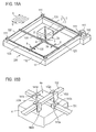
- Fig. 18 represents an arrangement in which the phantom 2 is formed with the solid dielectric 10' in the form of a relatively flat cube.
- a probe insertion opening 21 is formed into one surface of the phantom 2 and extends close to the opposite surface 2a.
- An electromagnetic field probe 1 is inserted into and secured in the inner end of the probe insertion opening 21, thus constructing an absorbed power measuring assembly 7. Securing the electromagnetic field probe 1 may take place, for example, by way of the adhesive 14 as illustrated in Fig. 7A .
- a radio transmitter 3 is disposed in proximity to the location of the electromagnetic field probe 1 within the phantom 2, and a scan takes place by a scan mechanism 100 while the radio transmitter 3 is disposed opposite to the phantom 2.
- the radio transmitter 3 is disposed close to and in parallel relationship with the surface 2a of the phantom 2 which is located close to the probe 1 while an antenna 5 of the radio transmitter 3 such as a mobile telephone extracts from a casing 3a.
- the radio transmitter 3 is mounted so that the casing 3a is held gripped by a retainer 4.
- the scan mechanism 100 may comprise drive screws 121, 122 extending along a pair of parallel sides of a rectangular frame-shaped base 110, for example, and rotatably mounted by four supports 111. Similarly, drive screws 123, 124 are rotatably mounted by the supports 111 on the other pair of parallel sides.
- a support bar 131 which extends parallel to the drive screws 121, 122 is formed with threaded holes at its opposite ends, which are threadably engaged with the drive screws 121, 122.
- a support bar 132 which extends parallel to the drive screws 123, 124 is formed with threaded holes at its opposite ends, which are threadably engaged with the drive screws 123, 124.
- the support bars 131 and 132 are slightly offset from each other in a direction perpendicular to the surface of the phantom 2 which is disposed opposite to the radio transmitter.
- pairs of opposing, inverted L-shaped engaging peaces 141 a and 141 b, 141 c and 141d, 142a and 142b, and 142c and 142d are fixedly mounted on the surface 4a of the retainer 4 which is disposed opposite from the phantom 2, and the support bar 131 passes between the pairs of engaging pieces 141 a and 141b and 141c and 141d so as to be slidable between the ends of these engaging pieces and the surface 4a of the retainer 4.
- the support bar 132 is passed between the pairs of engaging pieces 142a and 142b and 142c and 142d so as to be slidable.
- the support bar 132 has its opposite lateral edges received in grooves formed in the ends of the engaging pieces 142a-142d, whereby its movement in a direction perpendicular to the surface 4a of the retainer is restricted.
- An arrangement is made such that the drive screws 121, 122 can be driven for rotation in forward and reverse directions by a controller 151 including a motor for example, and the drive screws 123, 124 can be driven for rotation in forward and reverse directions by a similar controller 152.
- An absorbed power measuring assembly 7 is mounted on a support 160 which is secured to the base 110 so that the surface 2a of the phantom 2 is disposed close to and opposite to the radio transmitter 3 which is retained by the retainer 4.
- the two-dimensional scan is capable of measuring the power absorbed from the radio wave over the entire surface 2a of the phantom 2 while the antenna feed point 3b of the radio transmitter 3 is disposed opposite to the probe 1.
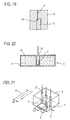
- Fig. 19 illustrates by way of example that an area 9, shown hatched, over the surface 2a of the phantom 2 can be measured relative to the radio transmitter 3.
- what is measured by the electromagnetic field probe 1 is values on the locus of scan 6, and values in interstices S between adjacent scan lines are interpolated from adjacent measured values.
- the measurement takes place at an interval on the scan line, and values in the interval are interpolated from adjacent measured values.
- the spacing between the adjacent scan lines may be chosen on the order of 1cm, for example.
- the range of measurement (area) 9 is preferably a rectangular range which is determined by the longitudinal length (inclusive of the antenna length) and the lateral length of the radio transmitter 3.
- the phantom 2 used may comprise an enclosed vessel 11 which is configured in the similar manner as shown in Fig. 18A and which is formed with a probe insertion opening 21, into which a liquid medium 10 is filled, as shown in Fig. 20 .
- the scan mechanism 100 allows a two-dimensional scan of the absorbed power measuring assembly 7 relative to the radio transmitter, and accordingly, the power absorbed from the radio wave by each part of the human body which corresponds to the phantom 2, can be measured with a high positional accuracy.
- a result which is similar to a result of measurement according to the measuring technique shown in Fig. 1 in which the probe 1 is moved for purpose of scan is obtained and the likelihood that the response of the liquid medium 10 may be changed due to the evaporation is avoided with the phantom 2 which uses the liquid medium 10.
- the scan mechanism 100 is not limited to the example described above, but a variety of X ⁇ Y drive mechanism may be used.
- a plurality of electromagnetic field probes 1 are fixedly mounted in a linear array within a phantom 2.
- a moving scan of a radio transmitter 3 obtains a range of measurement shown in Fig. 19 with a stroke corresponding to a spacing S1 between the electromagnetic field probes 1 in the direction of the array of the electromagnetic field probes 1.
- the probes 1 are arrayed in a direction parallel to the lengthwise direction of the radio transmitter 3, but may be arrayed in a direction perpendicular to the lengthwise direction.
- a plurality of electromagnetic field probes 1 may be arrayed in a matrix in a plane which is close to the surface 2a of a phantom 2.
- a measurement over the range shown in Fig. 19 can be obtained by scanning in one direction of the array of the electromagnetic probes 1 through a stroke corresponding to a spacing S1 and scanning in the other direction of the array through a stroke corresponding to a spacing S2.
- a value or values located between measuring points are interpolated from adjacent measured values.
- the scan stroke is shorter than in the example shown in Fig. 18 , and the measurement can be completed in a shorter time interval and a scan mechanism 100 can be constructed in a compact form.
- the time interval of measurement can be made shorter and the scan mechanism can be constructed in a smaller size.
- a radio transmitter 3 when a radio transmitter 3 is brought to a position A during a moving scan or when the majority of the radio transmitter 3 is located opposite to a phantom 2, the radiation characteristics of the radio transmitter 3 is strongly influenced by the phantom 2, but at position B or when a significant portion of the radio transmitter 3 is not disposed opposite to the phantom 2 or misaligned therewith, the radiation characteristics of the radio transmitter 3 is influenced by both the phantom 2 and the air.
- the configuration of a phantom 2 may be chosen to be in the form of a flat plate having an infinity size as seen by a radio transmitter 3, with the radio transmitter 3 disposed opposite to a central portion of one surface of the plate-shaped phantom 2.
- the influence of the phantom upon the radiation characteristics of the radio transmitter 3 can be made substantially uniform at any position of the radio transmitter 3 during its moving scan.
- part of the human body which is located close to the radio transmitter 3 is more planar and its area is greater, the absorption of the radio wave occurs more strongly. Accordingly, when an absorbed power measuring apparatus is constructed in the manner shown in Fig. 24 , a maximum value evaluation can be made.
- its length L1 as measured in the direction in which an antenna 5 extends should be equal to or greater than 0.6 ⁇
- its length L2 in a direction perpendicular to the antenna 5 should be equal to or greater than 0.5 ⁇
- its thickness L3 should be equal to or greater than 0.3 ⁇ where ⁇ represents the wavelength of a radio wave transmitted from the radio transmitter 3.
- the phantom 2 may be one which simulates respective part of an actual human body as illustrated in Figs. 7 , 16 and 17 or one which employs an geometrically simple configuration. However, it is not necessary that the volume of the phantom 2 be equal to the volume of a corresponding part of the human body. In any event, the measurement takes place by a moving scan of the absorbed power measuring assembly 7 and the actual line transmitter 3 relative to each other using the scan mechanism 100 shown in Fig. 18 or the like, for example.
- a belt conveyor 31 is maintained substantially horizontal across its width and runs substantially horizontally.
- a drive mechanism for the belt conveyor 31 is not shown in the drawing.
- a phantom 2 as mounted on a support 160 is fixedly mounted over the belt conveyor 31.
- the surface 2a of the phantom 2 which is located close to a probe 1 is disposed opposite to the belt conveyor 31 with a spacing D1 with respect to the top surface of the belt conveyor 31.
- the radio transmitter 3 is placed on the belt conveyor 31 so that its lengthwise direction extends in the crosswise direction of the belt conveyor 31 and the direction of thickness of a casing 3a extends perpendicular to the top surface of the belt conveyor 31. Substantially the entire length of the radio transmitter 3 passes under the phantom 2, and the spacing D1 is chosen so that the surface 2a of the phantom 2 is disposed as close to the radio transmitter 3 as possible.
- the radio transmitter 3 is placed on an upstream portion of the belt conveyor 31, and as the radio transmitter 3 passes under the phantom 2, a linear scan takes place between the radio transmitter 3 and an absorbed power measuring assembly 7, thus enabling a measurement.
- a measurement of the power absorbed by the phantom 2 can be automatically made for a number of radio transmitters 3.
- a phantom 2 in the form of a flat plate has an infinity size as viewed from the radio transmitter 3, thus preventing the radiation characteristics of the radio transmitter 3 and the antenna reflected power from changing as long as the radio transmitter 3 is disposed opposite to the phantom 2.
- a plurality of phantoms 2 which may be three in number, having an identical configuration and formed of an identical material are fixedly mounted as an array in a direction in which a belt conveyor 31 runs.
- an electromagnetic field probe 1 is fixedly mounted in each phantom 2 at a mutually different position as viewed in the crosswise direction of the belt conveyor 31.
- the phantom 2 has a size which corresponds to a part of the human body.
- the phantom 2 shown in Figs. 2 , 18A and 20 may be used.
- measured values from the two-dimensional scan include contributions of configuration of the part of the human body while the response of each phantom 2 is little influenced by the electromagnetic field probes 1.
- the shift of position of the electromagnetic field probes 1 between different phantoms 2 may be chosen in the running direction rather than in the crosswise direction of the belt conveyor, or may be chosen in any other suitable manner.
- a plurality of phantoms 2, which may be three in number, for example, having an identical configuration and formed with an identical material may be fixedly mounted as an array in the running direction of the belt conveyor 31, and an electromagnetic field probe 1 is mounted at the same position, for example, at the center of each phantom 2.
- each radio transmitter 3 is subject to the measurement of absorbed power by three absorbed power measuring assemblies 7 under the same condition.
- a mean value of a plurality of measured values for each radio transmitter 3 may be chosen to define the power absorbed from the radio wave from this radio transmitter 3, or a maximum value among a plurality of measured values for each radio transmitter 3 may be chosen to define the power absorbed from the radio wave from this radio transmitter 3.
- the process of determining such a mean value or a maximum value takes place in the calculation and display unit 80 shown in Fig. 7 .
- a position sensor 51 is mounted on a phantom 2 in order to improve the accuracy of measuring position.
- the position sensor 51 is mounted on the phantom 2 so that its position relative to the probe 1 can be defined, thus detecting whether or not the position sensor 51 is located opposite to a radio transmitter 3.
- the position sensor 51 detects whether or not it is located opposite to the radio transmitter 3 by radiating an infrared pulse beam in a direction perpendicular to the surface 2a of the phantom 2, for example, and determining a time interval until a reflected infrared pulse is received or the strength of the reflected infrared pulse.
- each point where the radio transmitter 3 has been detected can be plotted, whereby the configuration of the radio transmitter 3 which opposes the phantom 2 is detected. Since the relative position between the probe 1 and the position sensor 51 in a plane parallel to the scan plane is fixed and is previously known, the position of each measuring point of the probe 1 with respect to the configuration of the detected radio transmitter 3 can be determined, and when the configuration of the radio transmitter 3 is determined with a high accuracy, the position of the measuring point of the probe 1 can be determined with a corresponding accuracy.
- the measuring position of the probe 1 relative to the radio transmitter 3 can be correctly determined by detecting the arrival of the radio transmitter 3 by the position sensor 51, if the position where the radio transmitter 3 is placed on the belt conveyor 31 is misaligned or the time interval to place it is offset.
- the position sensors 51 As shown in Fig. 31 , by disposing the position sensors 51 so as to surround the probe 1, the positional relationship between the radio transmitter 3 and the probe 1 can be determined with a better accuracy.
- Fig. 32 shows an exemplary construction in which an absorbed power measuring assembly 7 and a scan mechanism 100 are enclosed in a radio anechoic box 41.
- this construction it is possible to prevent an electromagnetic field probe 1 from detecting undesired radio waves and to prevent a leakage of the radio wave radiated by a radio transmitter 3 to the exterior.
- a pair of opposing walls of the radio anechoic box 41 are formed with openings 41 a, 41 b in opposing relationship so as to pass the belt conveyor 31 therethrough, and metal tubes 42a, 42b are mounted to connect with the openings 41 a, 41 b, as shown in Fig. 33 .
- the openings of the tubes 42a, 42b are chosen so that their cut-off frequency is higher than the frequency of the radio wave radiated from the radio transmitter 3 within the radio anechoic box 41, thus preventing the radio wave from the radio transmitter 3 from passing through the tubes 42a, 42b.
- cloths 43a, 43b woven with metal are attached to the upper edges of the openings 41 a, 41 b of the radio anechoic box 41 to hang therefrom, as shown in Fig. 34 , thus causing the cloths 43a, 43b to be forced out of the way by the radio transmitter 3 as it passes through the openings 41 a, 41 b.
- a phantom using the liquid medium 10 as well as the solid dielectric 10' may be used also in the embodiments shown in Figs. 21 to 34 . It is also desirable according to the invention that the probe 1 be disposed within 20mm from the surface 2a of the phantom which faces the radio transmitter 3.
Landscapes
- Physics & Mathematics (AREA)
- Electromagnetism (AREA)
- General Physics & Mathematics (AREA)
- Measurement And Recording Of Electrical Phenomena And Electrical Characteristics Of The Living Body (AREA)
- Testing Electric Properties And Detecting Electric Faults (AREA)
- Arrangements For Transmission Of Measured Signals (AREA)
- Radar Systems Or Details Thereof (AREA)
Applications Claiming Priority (3)
| Application Number | Priority Date | Filing Date | Title |
|---|---|---|---|
| JP2001240926 | 2001-08-08 | ||
| JP2002068521 | 2002-03-13 | ||
| EP02755876.6A EP1326070B1 (fr) | 2001-08-08 | 2002-08-08 | Dispositif de mesure de la puissance d'absorption |
Related Parent Applications (1)
| Application Number | Title | Priority Date | Filing Date |
|---|---|---|---|
| EP02755876.6 Division | 2002-08-08 |
Publications (2)
| Publication Number | Publication Date |
|---|---|
| EP2199811A1 true EP2199811A1 (fr) | 2010-06-23 |
| EP2199811B1 EP2199811B1 (fr) | 2013-01-09 |
Family
ID=26620199
Family Applications (2)
| Application Number | Title | Priority Date | Filing Date |
|---|---|---|---|
| EP10156892A Expired - Lifetime EP2199811B1 (fr) | 2001-08-08 | 2002-08-08 | Appareil pour déterminer le taux d'absorption spécifique (SAR) d'un transmitteur, en particulier d'un téléphone portable, en faisant passer le transmitteur devant un Phantom solide, sec contenant un intensimètre noyé |
| EP02755876.6A Expired - Lifetime EP1326070B1 (fr) | 2001-08-08 | 2002-08-08 | Dispositif de mesure de la puissance d'absorption |
Family Applications After (1)
| Application Number | Title | Priority Date | Filing Date |
|---|---|---|---|
| EP02755876.6A Expired - Lifetime EP1326070B1 (fr) | 2001-08-08 | 2002-08-08 | Dispositif de mesure de la puissance d'absorption |
Country Status (6)
| Country | Link |
|---|---|
| US (2) | US7186377B2 (fr) |
| EP (2) | EP2199811B1 (fr) |
| JP (1) | JP3809166B2 (fr) |
| CN (2) | CN100422726C (fr) |
| CA (1) | CA2421821C (fr) |
| WO (1) | WO2003014717A1 (fr) |
Families Citing this family (34)
| Publication number | Priority date | Publication date | Assignee | Title |
|---|---|---|---|---|
| CN100422726C (zh) * | 2001-08-08 | 2008-10-01 | 株式会社Ntt都科摩 | 吸收功率测量装置 |
| US20030179149A1 (en) * | 2001-11-26 | 2003-09-25 | Schlumberger Electricity, Inc. | Embedded antenna apparatus for utility metering applications |
| FR2859064B1 (fr) * | 2003-08-18 | 2005-12-30 | Satimo Sa | Dispositif de controle du debit d'absorption specifique d'objets rayonnants fabriques en serie et notamment de telephones portables |
| CN100443889C (zh) * | 2004-07-05 | 2008-12-17 | 株式会社Ntt都科摩 | 比吸收率测量装置 |
| JP5554463B2 (ja) * | 2004-07-05 | 2014-07-23 | 株式会社Nttドコモ | 比吸収率測定装置 |
| JP2006132970A (ja) * | 2004-11-02 | 2006-05-25 | Ntt Docomo Inc | 比吸収率測定システム及び方法 |
| US7921741B2 (en) * | 2004-12-15 | 2011-04-12 | Motorola Mobility, Inc. | Electromagnetic testing model of human hand |
| US20060199159A1 (en) * | 2005-03-01 | 2006-09-07 | Neuronetics, Inc. | Head phantom for simulating the patient response to magnetic stimulation |
| JP4127838B2 (ja) * | 2005-03-31 | 2008-07-30 | 株式会社東芝 | 電磁界プローブ |
| US8502546B2 (en) * | 2006-04-05 | 2013-08-06 | Emscan Corporation | Multichannel absorberless near field measurement system |
| US7843391B2 (en) * | 2006-09-15 | 2010-11-30 | Itron, Inc. | RF local area network antenna design |
| JP5669337B2 (ja) | 2006-10-23 | 2015-02-12 | 株式会社Nttドコモ | 比吸収率を測定するためのシステム及び方法 |
| WO2008051125A1 (fr) * | 2006-10-27 | 2008-05-02 | Telefonaktiebolaget Lm Ericsson (Publ) | Mesure d'absorption rapide |
| CN1964547A (zh) * | 2006-11-30 | 2007-05-16 | 中兴通讯股份有限公司 | 确定天线最小测试距离的方法 |
| JP4819663B2 (ja) * | 2006-12-13 | 2011-11-24 | 株式会社エヌ・ティ・ティ・ドコモ | 複素誘電率測定装置及び複素誘電率測定方法 |
| US8301133B2 (en) | 2006-12-20 | 2012-10-30 | Research In Motion Limited | Method and system for conducting hearing aid compatibility testing of a mobile communication device |
| DE102007007686A1 (de) * | 2007-02-16 | 2008-08-21 | Forschungszentrum Jülich GmbH | Phantom |
| US20080261584A1 (en) * | 2007-04-23 | 2008-10-23 | Research In Motion Limited | Method and system for conducting specific absorption rate testing of a mobile communication device |
| FR2932894B1 (fr) * | 2008-06-23 | 2010-09-24 | Satimo Sa | Perfectionnements a la determination d'au moins une grandeur associee au rayonnement electromagnetique d'un objet sous test. |
| JP5221752B2 (ja) | 2009-03-03 | 2013-06-26 | 株式会社エヌ・ティ・ティ・ドコモ | 局所平均吸収電力測定方法、局所平均吸収電力算出装置、局所平均吸収電力算出プログラム |
| JP5619560B2 (ja) * | 2010-10-13 | 2014-11-05 | T&A株式会社 | 局所sar測定装置およびそれに用いる平面型軽量ファントム |
| US9759693B2 (en) * | 2012-12-20 | 2017-09-12 | International Business Machines Corporation | Method of simulating the absorption of plane waves using FEM software tools |
| JP2013101140A (ja) * | 2013-01-21 | 2013-05-23 | Ntt Docomo Inc | 比吸収率測定システム及び方法 |
| WO2016138073A1 (fr) * | 2015-02-24 | 2016-09-01 | Zte(Usa) Inc. | Procédés et équipement utilisateur permettant de mesurer la puissance émise d'un dispositif sans fil à proximité d'un fantôme |
| WO2016140870A2 (fr) * | 2015-03-02 | 2016-09-09 | Zte (Usa) Inc. | Procédés d'utilisation d'un fantôme de main permettant d'évaluer des tablettes dans un système de communication sans fil |
| FR3039282B1 (fr) * | 2015-07-24 | 2020-12-25 | Univ Rennes | Dispositif pour la dosimetrie electromagnetique et methode associee |
| IT201600079679A1 (it) * | 2016-07-28 | 2018-01-28 | Technoprobe Spa | Scheda di misura di dispositivi elettronici |
| RU2665357C1 (ru) * | 2017-08-07 | 2018-08-29 | Акционерное общество "Научно-производственное предприятие "Алмаз" (АО "НПП "Алмаз") | Способ дискретного измерения дифференциального затухания электромагнитной волны в плёночных локальных поглотителях замедляющих систем приборов свч с длительным взаимодействием |
| CN109142458A (zh) * | 2018-08-26 | 2019-01-04 | 昆山亿趣信息技术研究院有限公司 | 一种sar测试用人体组织模拟液 |
| CN109270361B (zh) * | 2018-10-10 | 2024-04-26 | 东莞华贝电子科技有限公司 | 移动终端的sar测试装置及方法 |
| CN109752601B (zh) * | 2018-12-06 | 2021-07-06 | 兰州空间技术物理研究所 | 一种测量离子推力器放电室壁面电荷动态特性的装置 |
| JP7407073B2 (ja) * | 2020-06-03 | 2023-12-28 | 富士フイルムヘルスケア株式会社 | 試験装置、試験方法及びファントム |
| EP4170360A1 (fr) | 2021-10-22 | 2023-04-26 | Université de Rennes 1 | Dispositif fantôme, système de dosimétrie électromagnétique associé |
| CN114818412B (zh) * | 2022-03-18 | 2022-09-27 | 北京航空航天大学 | 一种人脑受电磁辐射的高精度计算方法 |
Citations (5)
| Publication number | Priority date | Publication date | Assignee | Title |
|---|---|---|---|---|
| JPH0989967A (ja) * | 1995-09-27 | 1997-04-04 | Kokusai Electric Co Ltd | 感度測定ボックス |
| JPH10185838A (ja) * | 1996-12-26 | 1998-07-14 | N T T Ido Tsushinmo Kk | 吸収電力測定装置 |
| KR20000004195A (ko) * | 1998-06-30 | 2000-01-25 | 윤종용 | 이동전화기 자동 검사장치 |
| WO2000004399A2 (fr) * | 1998-07-14 | 2000-01-27 | Deutsche Telekom Ag | Dispositif de mesure du taux d'absorption specifique |
| WO2002056041A1 (fr) * | 2001-01-16 | 2002-07-18 | Telefonaktiebolaget Lm Ericsson (Publ) | Chambre pour et procede de traitement d'appareils electroniques et utilisation de cette chambre |
Family Cites Families (11)
| Publication number | Priority date | Publication date | Assignee | Title |
|---|---|---|---|---|
| US5291422A (en) * | 1992-01-28 | 1994-03-01 | Sgi International | Broadband instrument for nondestructive measurement of material properties |
| JP2737661B2 (ja) * | 1994-09-21 | 1998-04-08 | 日本電気株式会社 | Sar測定方法およびsar測定装置 |
| JP2790103B2 (ja) * | 1995-12-15 | 1998-08-27 | 日本電気株式会社 | 比吸収率測定装置及び比吸収率測定方法 |
| JPH10311805A (ja) * | 1997-05-09 | 1998-11-24 | N T T Ido Tsushinmo Kk | 吸収電力測定装置及びその校正方法 |
| KR100246538B1 (ko) * | 1997-10-24 | 2000-03-15 | 정선종 | 전자파 환경 평가용 형상기억 인체팬텀의 제조 방법 |
| JP3094975B2 (ja) * | 1997-11-13 | 2000-10-03 | 日本電気株式会社 | Sar測定装置 |
| JP2001124707A (ja) * | 1999-10-28 | 2001-05-11 | Mokuzai Kanso Teicostka Gijutsu Kenkyu Kumiai | 木材の水分測定方法及びその装置 |
| WO2001086311A1 (fr) * | 2000-05-05 | 2001-11-15 | Integra Antennas Ltd | Ensemble tete fantome et procede pour mesurer l'incidence d'ondes electromagnetiques au moyen de cette tete fantome |
| US6329953B1 (en) * | 2000-09-29 | 2001-12-11 | Rangestar Wireless | Method and system for rating antenna performance |
| CN100422726C (zh) * | 2001-08-08 | 2008-10-01 | 株式会社Ntt都科摩 | 吸收功率测量装置 |
| DE60300464T2 (de) * | 2002-04-22 | 2006-02-23 | Matsushita Electric Industrial Co., Ltd., Kadoma | Vorrichtung zur Messung der spezifischen Absorptionsrate auf der Basis des magnetischen Nahfeldes zur Anwendung in einem Radioapparat |
-
2002
- 2002-08-08 CN CNB2005100516514A patent/CN100422726C/zh not_active Expired - Fee Related
- 2002-08-08 CN CNB028027698A patent/CN1277115C/zh not_active Expired - Fee Related
- 2002-08-08 CA CA002421821A patent/CA2421821C/fr not_active Expired - Fee Related
- 2002-08-08 JP JP2003519398A patent/JP3809166B2/ja not_active Expired - Fee Related
- 2002-08-08 WO PCT/JP2002/008125 patent/WO2003014717A1/fr not_active Ceased
- 2002-08-08 US US10/398,205 patent/US7186377B2/en not_active Expired - Fee Related
- 2002-08-08 EP EP10156892A patent/EP2199811B1/fr not_active Expired - Lifetime
- 2002-08-08 EP EP02755876.6A patent/EP1326070B1/fr not_active Expired - Lifetime
-
2006
- 2006-03-30 US US11/392,570 patent/US7615188B2/en not_active Expired - Fee Related
Patent Citations (5)
| Publication number | Priority date | Publication date | Assignee | Title |
|---|---|---|---|---|
| JPH0989967A (ja) * | 1995-09-27 | 1997-04-04 | Kokusai Electric Co Ltd | 感度測定ボックス |
| JPH10185838A (ja) * | 1996-12-26 | 1998-07-14 | N T T Ido Tsushinmo Kk | 吸収電力測定装置 |
| KR20000004195A (ko) * | 1998-06-30 | 2000-01-25 | 윤종용 | 이동전화기 자동 검사장치 |
| WO2000004399A2 (fr) * | 1998-07-14 | 2000-01-27 | Deutsche Telekom Ag | Dispositif de mesure du taux d'absorption specifique |
| WO2002056041A1 (fr) * | 2001-01-16 | 2002-07-18 | Telefonaktiebolaget Lm Ericsson (Publ) | Chambre pour et procede de traitement d'appareils electroniques et utilisation de cette chambre |
Non-Patent Citations (11)
| Title |
|---|
| BAHR A ET AL: "COMPARISON BETWEEN NUMERICAL AND EXPERIMENTAL NEAR-FIELD EVALUATION OF A DCS1800 MOBILE TELEPHONE", RADIO SCIENCE, AMERICAN GEOPHYSICAL UNION, WASHINGTON, DC, US LNKD- DOI:10.1029/98RS02352, vol. 33, no. 6, 1 November 1998 (1998-11-01), pages 1553 - 1563, XP008023500, ISSN: 0048-6604 * |
| BALZANO Q ET AL: "ELECTROMAGNETIC ENERGY EXPOSURE OF SIMULATED USERS OF PORTABLE CELLULAR TELEPHONES", IEEE TRANSACTIONS ON VEHICULAR TECHNOLOGY, IEEE SERVICE CENTER, PISCATAWAY, NJ, US LNKD- DOI:10.1109/25.406605, vol. 44, no. 3, 1 August 1995 (1995-08-01), pages 390 - 403, XP000526029, ISSN: 0018-9545 * |
| BENDIEBARA N ET AL: "Statistical analysis and characterization of spatial distribution of absorbed power of GSM mobile phones", IEEE ANTENNAS AND PROPAGATION SOCIETY INTERNATIONAL SYMPOSIUM. 2001 DIGEST. APS. BOSTON, MA, JULY 8 - 13, 2001; [IEEE ANTENNAS AND PROPAGATION SOCIETY INTERNATIONAL SYMPOSIUM], NEW YORK, NY : IEEE, US LNKD- DOI:10.1109/APS.2001.959621, vol. 2, 8 July 2001 (2001-07-08), pages 60 - 63, XP010564031, ISBN: 978-0-7803-7070-8 * |
| H. TAMURA; Y. ISHIKAWA; T. KOBAYASHI; T. NOJIMA: "A Dry Phantom Material Composed of Ceramic and Graphite Powder", IEEE TRANS. ELECTROMAGN. COMPAT., vol. 39, no. 2, 1997, pages 132 - 137 |
| IYAMA T ET AL: "LOCAL SAR ESTIMATION SYSTEM USING SOLID PHANTOM AND FIXED E-FIELD PROBE", ELECTRONICS & COMMUNICATIONS IN JAPAN, PART I - COMMUNICATIONS, WILEY, HOBOKEN, NJ, US LNKD- DOI:10.1002/ECJA.10082, vol. 86, no. 9, PART 01, 1 January 2003 (2003-01-01), pages 46 - 56, XP001160104, ISSN: 8756-6621 * |
| KARL S. KUNG; RAYMOND J. LUEBBERS: "Finite Difference Time Domain Method for Electromagnetics", 1993, CRC PRESS |
| KUSTER N ET AL: "DOSIMETRIC EVALUATION OF HANDHELD MOBILE COMMUNICATIONS EQUIPMENT WITH KNON PRECISION", 1 May 1997, IEICE TRANSACTIONS ON COMMUNICATIONS, COMMUNICATIONS SOCIETY, TOKYO, JP, PAGE(S) 645 - 651, ISSN: 0916-8516, XP000723037 * |
| NOJIMA T ET AL: "An easy handling SAR meter for cellular and personal portable radios", PROC. URSI,, 1 January 1999 (1999-01-01), XP009132013 * |
| RUOSS H-O ET AL: "FAST AND ACCURATE SAR-TESTING OF HAND-HELD MOBILE TELEPHONES: MEASUREMENT TECHNIQUE SET-UP AND FIRST ASSESSMENT OF ACCURACY", AEU INTERNATIONAL JOURNAL OF ELECTRONICS AND COMMUNICATIONS, ELSEVIER, JENA, DE, vol. 54, no. 3, 1 January 2000 (2000-01-01), pages 155 - 162, XP001124117, ISSN: 1434-8411 * |
| TARUSAWA YOSHIAKI ET AL: "Local SAR Estimation Method Using Solid Dielectrics and E-field Probes", PROCEEDINGS OF THE SOCIETY CONFERENCE OF IEICE, ENGINEERS, vol. B-4-32, 16 August 1999 (1999-08-16), pages 216, XP009132073 * |
| WANG J ET AL: "DOSIMETRIC EVALUATION OF HUMAN HEAD FOR PORTABLE TELEPHONES", ELECTRONICS & COMMUNICATIONS IN JAPAN, PART I - COMMUNICATIONS, WILEY, HOBOKEN, NJ, US LNKD- DOI:10.1002/ECJA.1107, vol. 85, no. 7, PART 01, 1 January 2001 (2001-01-01), pages 12 - 22, XP001102663, ISSN: 8756-6621 * |
Also Published As
| Publication number | Publication date |
|---|---|
| JP3809166B2 (ja) | 2006-08-16 |
| US20060172432A1 (en) | 2006-08-03 |
| EP2199811B1 (fr) | 2013-01-09 |
| JPWO2003014717A1 (ja) | 2004-11-25 |
| US20040102694A1 (en) | 2004-05-27 |
| US7186377B2 (en) | 2007-03-06 |
| CN1651907A (zh) | 2005-08-10 |
| EP1326070A1 (fr) | 2003-07-09 |
| US7615188B2 (en) | 2009-11-10 |
| EP1326070B1 (fr) | 2013-07-10 |
| CA2421821A1 (fr) | 2003-03-07 |
| CN1277115C (zh) | 2006-09-27 |
| CN100422726C (zh) | 2008-10-01 |
| CN1473268A (zh) | 2004-02-04 |
| EP1326070A4 (fr) | 2005-02-02 |
| WO2003014717A1 (fr) | 2003-02-20 |
| CA2421821C (fr) | 2007-07-31 |
Similar Documents
| Publication | Publication Date | Title |
|---|---|---|
| US7615188B2 (en) | Apparatus for measuring absorbed power | |
| US7444264B2 (en) | Method and an apparatus for measuring the performance of antennas, mobile phones and other wireless terminals | |
| EP2721424B1 (fr) | Procédé et appareil améliorés pour mesurer la performance d'antennes, de téléphones mobiles et d'autres terminaux sans fil | |
| US20200076064A1 (en) | System, method and computer-accessible medium for compliance assessment and active power management for safe use of radiowave emitting devices | |
| US9699678B2 (en) | Plane wave generation within a small volume of space for evaluation of wireless devices | |
| US20080265902A1 (en) | Specific absorption rate measurement system and method | |
| CN100504407C (zh) | 用于控制大量生产的辐射体的比吸收率的设备 | |
| Flintoft et al. | On the measurable range of absorption cross section in a reverberation chamber | |
| Ma et al. | Reducing the number of measurement nodes in RF imaging using antenna-pattern diversity with an extended Rytov approximation | |
| Sultan et al. | On-body cavity-backed slot antenna with pattern and polarization diversity for medical imaging | |
| CA2550158C (fr) | Dispositif de mesure de la puissance d'absorption | |
| JP2000214201A (ja) | アンテナ測定方法及び測定装置 | |
| KR100600476B1 (ko) | 전자파흡수율 측정 시스템 및 그 방법 | |
| Iyama et al. | Whole-body average SAR measurement using flat phantoms for radio base station antennas and its applicability to adult and child human models | |
| Davis et al. | International intercomparison of specific absorption rates in a flat absorbing phantom in the near-field of dipole antennas | |
| Kantartzis et al. | Time-Domain Characterization of EMC Test Facilities | |
| Hakim et al. | Precise dielectric property measurements and E-field probe calibration for specific absorption rate measurements using a rectangular waveguide | |
| JPH10311805A (ja) | 吸収電力測定装置及びその校正方法 | |
| Gasperini et al. | Optimized Metasurface Matching Layer for Biomedical Applications in Near Field [Electromagnetic Metamaterials] | |
| CN115166733A (zh) | 一种便携式无损重构微波成像仪 | |
| Stevens et al. | Study of interpolation and extrapolation techniques for SAR measurements | |
| Fabiano et al. | Electromagnetic Fields in Proximity of GSM Base Stations |
Legal Events
| Date | Code | Title | Description |
|---|---|---|---|
| PUAI | Public reference made under article 153(3) epc to a published international application that has entered the european phase |
Free format text: ORIGINAL CODE: 0009012 |
|
| AC | Divisional application: reference to earlier application |
Ref document number: 1326070 Country of ref document: EP Kind code of ref document: P |
|
| AK | Designated contracting states |
Kind code of ref document: A1 Designated state(s): CH DE FR GB IT LI SE |
|
| 17P | Request for examination filed |
Effective date: 20100803 |
|
| GRAP | Despatch of communication of intention to grant a patent |
Free format text: ORIGINAL CODE: EPIDOSNIGR1 |
|
| GRAS | Grant fee paid |
Free format text: ORIGINAL CODE: EPIDOSNIGR3 |
|
| GRAA | (expected) grant |
Free format text: ORIGINAL CODE: 0009210 |
|
| AC | Divisional application: reference to earlier application |
Ref document number: 1326070 Country of ref document: EP Kind code of ref document: P |
|
| AK | Designated contracting states |
Kind code of ref document: B1 Designated state(s): CH DE FR GB IT LI SE |
|
| REG | Reference to a national code |
Ref country code: GB Ref legal event code: FG4D |
|
| REG | Reference to a national code |
Ref country code: CH Ref legal event code: EP |
|
| REG | Reference to a national code |
Ref country code: CH Ref legal event code: NV Representative=s name: E. BLUM AND CO. AG PATENT- UND MARKENANWAELTE , CH |
|
| REG | Reference to a national code |
Ref country code: CH Ref legal event code: NV Representative=s name: E. BLUM AND CO. AG PATENT- UND MARKENANWAELTE , CH |
|
| REG | Reference to a national code |
Ref country code: SE Ref legal event code: TRGR |
|
| REG | Reference to a national code |
Ref country code: DE Ref legal event code: R096 Ref document number: 60244401 Country of ref document: DE Effective date: 20130307 |
|
| PGFP | Annual fee paid to national office [announced via postgrant information from national office to epo] |
Ref country code: FR Payment date: 20130702 Year of fee payment: 12 |
|
| PGFP | Annual fee paid to national office [announced via postgrant information from national office to epo] |
Ref country code: CH Payment date: 20130704 Year of fee payment: 12 Ref country code: SE Payment date: 20130813 Year of fee payment: 12 Ref country code: DE Payment date: 20130831 Year of fee payment: 12 |
|
| PLBE | No opposition filed within time limit |
Free format text: ORIGINAL CODE: 0009261 |
|
| STAA | Information on the status of an ep patent application or granted ep patent |
Free format text: STATUS: NO OPPOSITION FILED WITHIN TIME LIMIT |
|
| PGFP | Annual fee paid to national office [announced via postgrant information from national office to epo] |
Ref country code: GB Payment date: 20130807 Year of fee payment: 12 |
|
| 26N | No opposition filed |
Effective date: 20131010 |
|
| PGFP | Annual fee paid to national office [announced via postgrant information from national office to epo] |
Ref country code: IT Payment date: 20130708 Year of fee payment: 12 |
|
| REG | Reference to a national code |
Ref country code: DE Ref legal event code: R097 Ref document number: 60244401 Country of ref document: DE Effective date: 20131010 |
|
| REG | Reference to a national code |
Ref country code: DE Ref legal event code: R119 Ref document number: 60244401 Country of ref document: DE |
|
| REG | Reference to a national code |
Ref country code: SE Ref legal event code: EUG Ref country code: CH Ref legal event code: PL |
|
| GBPC | Gb: european patent ceased through non-payment of renewal fee |
Effective date: 20140808 |
|
| PG25 | Lapsed in a contracting state [announced via postgrant information from national office to epo] |
Ref country code: LI Free format text: LAPSE BECAUSE OF NON-PAYMENT OF DUE FEES Effective date: 20140831 Ref country code: CH Free format text: LAPSE BECAUSE OF NON-PAYMENT OF DUE FEES Effective date: 20140831 Ref country code: IT Free format text: LAPSE BECAUSE OF NON-PAYMENT OF DUE FEES Effective date: 20140808 |
|
| REG | Reference to a national code |
Ref country code: DE Ref legal event code: R119 Ref document number: 60244401 Country of ref document: DE Effective date: 20150303 |
|
| PG25 | Lapsed in a contracting state [announced via postgrant information from national office to epo] |
Ref country code: SE Free format text: LAPSE BECAUSE OF NON-PAYMENT OF DUE FEES Effective date: 20140809 |
|
| REG | Reference to a national code |
Ref country code: FR Ref legal event code: ST Effective date: 20150430 |
|
| PG25 | Lapsed in a contracting state [announced via postgrant information from national office to epo] |
Ref country code: GB Free format text: LAPSE BECAUSE OF NON-PAYMENT OF DUE FEES Effective date: 20140808 Ref country code: DE Free format text: LAPSE BECAUSE OF NON-PAYMENT OF DUE FEES Effective date: 20150303 |
|
| PG25 | Lapsed in a contracting state [announced via postgrant information from national office to epo] |
Ref country code: FR Free format text: LAPSE BECAUSE OF NON-PAYMENT OF DUE FEES Effective date: 20140901 |
|
| P01 | Opt-out of the competence of the unified patent court (upc) registered |
Effective date: 20230520 |