EP2199827B1 - Filtrage de signal d'écho parasite pour un signal de Doppler - Google Patents
Filtrage de signal d'écho parasite pour un signal de Doppler Download PDFInfo
- Publication number
- EP2199827B1 EP2199827B1 EP09179074.1A EP09179074A EP2199827B1 EP 2199827 B1 EP2199827 B1 EP 2199827B1 EP 09179074 A EP09179074 A EP 09179074A EP 2199827 B1 EP2199827 B1 EP 2199827B1
- Authority
- EP
- European Patent Office
- Prior art keywords
- signal
- doppler
- doppler signal
- ifr
- clutter
- Prior art date
- Legal status (The legal status is an assumption and is not a legal conclusion. Google has not performed a legal analysis and makes no representation as to the accuracy of the status listed.)
- Active
Links
Images


Classifications
-
- A—HUMAN NECESSITIES
- A61—MEDICAL OR VETERINARY SCIENCE; HYGIENE
- A61B—DIAGNOSIS; SURGERY; IDENTIFICATION
- A61B8/00—Diagnosis using ultrasonic, sonic or infrasonic waves
- A61B8/13—Tomography
- A61B8/14—Echo-tomography
-
- G—PHYSICS
- G01—MEASURING; TESTING
- G01S—RADIO DIRECTION-FINDING; RADIO NAVIGATION; DETERMINING DISTANCE OR VELOCITY BY USE OF RADIO WAVES; LOCATING OR PRESENCE-DETECTING BY USE OF THE REFLECTION OR RERADIATION OF RADIO WAVES; ANALOGOUS ARRANGEMENTS USING OTHER WAVES
- G01S15/00—Systems using the reflection or reradiation of acoustic waves, e.g. sonar systems
- G01S15/88—Sonar systems specially adapted for specific applications
- G01S15/89—Sonar systems specially adapted for specific applications for mapping or imaging
- G01S15/8906—Short-range imaging systems; Acoustic microscope systems using pulse-echo techniques
- G01S15/8979—Combined Doppler and pulse-echo imaging systems
- G01S15/8981—Discriminating between fixed and moving objects or between objects moving at different speeds, e.g. wall clutter filter
Definitions
- the present disclosure relates to ultrasound signal processing, and more particularly to clutter signal filtering for Doppler signal in an ultrasound system.
- an ultrasound system has been extensively used in the medical field due to its non-invasive and non-destructive nature.
- Modern high-performance ultrasound imaging diagnostic systems and techniques are commonly used to produce two- or three-dimensional ultrasound images of internal features of patients.
- the ultrasound system operates in various image modes such as a brightness mode, a Doppler mode and the like to acquire ultrasound images for diagnosis.
- the ultrasound system provides a color flow image showing velocities of moving objects such as blood flow, heart, etc.
- the color flow image may be formed based on a Doppler signal obtained by alternately transmitting and receiving ultrasound signals to and from a target object.
- the Doppler signal may include a low frequency signal (the so-called clutter signal) due to the motion of a cardiac wall or valve of a heart.
- the clutter signal may have amplitude, which is over 100 times than that of a pure Doppler signal indicative of velocities of the blood flow.
- the clutter signal may be an obstacle to accurately detect a velocity of the blood flow. Thus, it is required to remove the clutter signal from the Doppler signal for accurate velocity detection of the blood flow.
- the ultrasound system typically adopts a clutter filter, which may be a high pass filter, to remove the clutter signal from the Doppler signal.
- Two clutter filtering methods have been adopted to remove the clutter signal from the Doppler signal.
- One is a clutter filtering method using a clutter power threshold.
- the other is a clutter filtering method using variance information of the clutter signal.
- the clutter filtering method using the clutter power threshold may be carried out by modulating the Doppler signal when the amplitude of the Doppler signal is greater than the clutter power threshold. Thereafter, the modulated Doppler signal may be filtered by using a clutter filter having a predetermined cutoff frequency. In such a method, however, if the amplitude of the Doppler signal is less than the clutter power threshold, then the modulation may not be performed. Also, when the power level of the pure Doppler signal is close to that of the clutter signal, the modulation may not be desirably performed. Thus, the clutter signal may not be effectively removed from the Doppler signal.
- the clutter filtering method using the variance information of clutter signal may be carried out by changing a cutoff frequency of a clutter filter.
- the clutter filter adopted in the conventional ultrasound system may remove the clutter signal in the Doppler signal by suppressing the frequency components thereof below a specific cutoff frequency. In such a case, however, if the cutoff frequency is set to a high value, then relatively low frequencies of the pure Doppler signal may be also cut off along with the clutter signal. Thus, it may be difficult to accurately detect the velocities of the blood flow.
- EP 0 524 774 A2 discloses an ultrasonic Doppler imaging apparatus in which the velocity of a blood flow in a living body can be computed with high precision without increasing a scale of a signal processing circuit, so that a Doppler color image having satisfactory image quality is displayed.
- an ultrasonic pulse signal is transmitted into the living body and is reflected from a target in the living body to be received by an ultrasonic probe, and the reception signal is subjected to quadrature phase detection to obtain an I signal and a Q signal.
- a power of a phase detection output signal applied to the input of an MTI filter is computed by an input power computing section and a power of the output signal of the MTI filter is computed by an output power computing section.
- XP004463713 "Adaptive clutter filtering for ultrasound color flow imaging" by Yang Mo Yoo et. al. discloses an adaptive clutter rejection method for selecting different clutter filters in ultrasound color flow imaging.
- XP032084664 "An improved wall filter for flow imaging of low velocity flow" by L. Thomas and A. Hall discloses methods for flow estimation for blood flow imaging.
- an ultrasound system includes the features of claim 1.
- a method of filtering clutter signal from Doppler signal comprises the features of claim 5.
- the ultrasound system 100 may include a Doppler signal acquisition unit 110.
- the Doppler signal acquisition unit 110 is operable to alternately transmit and receive ultrasound signals to and from a target object (e.g., heart, blood flow, etc) in synchronization with a pulse repetition frequency (PRF) to thereby acquire a Doppler signal.
- the Doppler signal may include a clutter signal due to the motion of cardiac walls or valves of a heart together with a pure Doppler signal indicating velocities of a blood flow.
- the Doppler signal acquisition unit 110 may include a transmit signal generator (not shown) configured to generate transmit pulse signals.
- the Doppler signal acquisition unit 110 may further include an ultrasound probe (not shown) that may be operable to transmit ultrasound signals to the target object in response to the transmit pulse signals and receive ultrasound echo signals reflected from the target object to thereby output an electrical receive signal.
- the Doppler signal acquisition unit 110 may further include a beam former (not shown), which may be operable to perform receive-focusing upon the electrical receive signal to obtain a receive-focused signal.
- the Doppler signal acquisition unit 110 may further include a Doppler signal forming section (not shown) that may be operable to sample the receive-focused signal at a predetermined sampling frequency and perform signal processing upon the sampled signal to acquire the Doppler signal.
- the ultrasound system 100 may further include a signal processing unit 120.
- the signal processing unit 120 is operable to analyze characteristics of the Doppler signal such as a mean power, mean velocity, variance, etc. thereof to determine whether to modulate the Doppler signal or change a cutoff frequency of a clutter filter necessary for clutter signal removal from the Doppler signal.
- the signal processing unit 120 is further operable to perform auto correlation, arc tangent operation, etc. upon the Doppler signal.
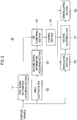
- FIG. 2 is a block diagram showing an illustrative embodiment of the signal processing unit 120.
- the signal processing unit 120 may include a first signal information forming section 121.
- the first signal information forming section 121 is operable to analyze the characteristics of the Doppler signal provided form the Doppler signal acquisition unit 110 to form first signal information.
- the first signal information may include a mean power, a mean velocity, a variance, etc. of the Doppler signal.
- the mean power P, the mean velocity V and the variance ⁇ may be computed by the following equations.
- the signal processing unit 120 may further include a first clutter filter 122 coupled to the Doppler signal acquisition unit 110 to receive the Doppler signal.
- the first clutter filter 122 is operable to perform filtering upon the Doppler signal to remove the clutter signal therefrom.
- the first clutter filter 122 may use a cutoff frequency to be set within about 10% from a half of the predetermined sampling frequency used to sample the receive-focused signal for acquiring the Doppler signal.
- the signal processing unit 120 may further include a second signal information forming section 123 coupled to the first clutter filter 122 to receive the filtered Doppler signal.
- the second signal information forming section 123 is operable to analyze the filtered Doppler signal to form second signal information.
- the second signal information may include a mean power, a mean velocity, variance, etc. of the filtered Doppler signal.
- the mean power, mean velocity and variance may be also computed by the above equations (1).
- the signal processing unit 120 may further include an input signal power to filtered input signal power rate (IFR) computing section 124 coupled to the first and second signal information forming sections 121 and 123 to receive the first and second signal information.
- IFR input signal power to filtered input signal power rate
- the signal processing unit 120 may further include a control section 125 coupled to the IFR computing section 124.
- the control section 125 is operable to compare the IFR with a predetermined threshold.
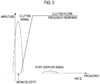
- a predetermined threshold When the Doppler signal having relatively high power exists in a low frequency region lower than PRF/2 on a frequency domain and a mean frequency representative of a mean velocity thereof is relatively low, as shown FIG. 3 , the IFR may be typically greater than 20. Thus, for example, 20 may be set as the predetermined threshold. If the IFR is greater than the predetermined threshold (e.g., 20), then the control section 125 is operable to generate a first control signal.
- the mean frequency representative of the mean velocity of the Doppler signal is positioned at the middle of the Doppler signal, as illustrated in FIG. 5 .
- the IFR may be a value ranging from 5 to 20. Since the mean velocity of the Doppler signal is largely different from the mean velocity of the clutter signal, the clutter signal may not be effectively removed through the clutter filtering method using a clutter power threshold. Thus, when the IFR is less than the predetermined threshold, the control section 125 is operable to generate a second control signal.
- the signal processing unit 120 may further include a modulating section 126 that may operate under the control of the control section 125.
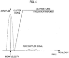
- the modulating section 126 is operable to set a predetermined modulation frequency in response to the first control signal and modulate the Doppler signal based on the predetermined modulation frequency to thereby output a modulated Doppler signal, as illustrated in FIG. 4 .
- the modulating section 126 is further operable to set the modulation frequency to zero in response to the second control signal. That is, if the second control signal is received from the control section 125, then the modulating section 126 may not modulate the Doppler signal.
- the signal processing unit 120 may further include a second clutter filter 127 that may operate under the control of the control section 125.
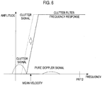
- the second clutter filter 127 is operable to perform filtering upon the modulated Doppler signal to remove the clutter signal therefrom by using a cutoff frequency, which is identical to that used in the first clutter filter 122, in response to the first control signal. That is, the cutoff frequency may be set to be within about 10% from a half of a sampling frequency used to sample the receive-focused signal for acquiring the Doppler signal. If the second control signal is received from the control section 125, then the second clutter filter 127 may be operable to adjust the cutoff frequency to remove the clutter signal from the Doppler signal, as illustrated in FIG. 6 . In such a case, the cutoff frequency may be changed based on a frequency representative of the mean velocity formed by the first signal information forming section 121.
- the signal processing unit 120 may further include a demodulating section 128.
- the demodulating section 128 is operable to set a demodulation frequency by using a frequency corresponding to the mean velocity formed by the first signal information forming section 121 in response to the first control signal.
- the demodulating section 128 is further operable to demodulate the modulated Doppler signal provided from the second clutter filter 127. If the second control signal is received, then the demodulating section 128 is operable to set the modulation frequency to zero. That is, the demodulating section 128 may not demodulate the Doppler signal outputted from the second clutter filter 127 in response to the second control signal.
- the ultrasound system 100 may further include an image forming unit 130.
- the image forming unit 130 is operable to form a Doppler image based on the Doppler signal outputted from the signal processing unit.
- the Doppler image may be displayed on a display unit 140.
- the display unit 140 may include at least one of CRT display, LCD, plate panel display and the like.
Landscapes
- Physics & Mathematics (AREA)
- Engineering & Computer Science (AREA)
- Radar, Positioning & Navigation (AREA)
- Remote Sensing (AREA)
- Acoustics & Sound (AREA)
- Health & Medical Sciences (AREA)
- Life Sciences & Earth Sciences (AREA)
- Computer Networks & Wireless Communication (AREA)
- General Physics & Mathematics (AREA)
- Radiology & Medical Imaging (AREA)
- Molecular Biology (AREA)
- Pathology (AREA)
- Biophysics (AREA)
- Biomedical Technology (AREA)
- Heart & Thoracic Surgery (AREA)
- Medical Informatics (AREA)
- Nuclear Medicine, Radiotherapy & Molecular Imaging (AREA)
- Surgery (AREA)
- Animal Behavior & Ethology (AREA)
- General Health & Medical Sciences (AREA)
- Public Health (AREA)
- Veterinary Medicine (AREA)
- Ultra Sonic Daignosis Equipment (AREA)
- Measurement Of Velocity Or Position Using Acoustic Or Ultrasonic Waves (AREA)
Claims (11)
- Système ultrasonique (100) comportant :une unité (110) d'acquisition d'un signal Doppler, configurée pour transmettre et recevoir des signaux ultrasoniques vers et de la part d'une cible pour acquérir un signal Doppler ; etune unité de traitement (120), configurée pour effectuer un filtrage du signal Doppler en utilisant un premier filtre (122) de parasites ayant une première fréquence de coupure et calculant une puissance de signal d'entrée du taux de puissance de signal d'entrée filtré, la vitesse, l'IFR pour le signal Doppler, caractérisé en ce que :l'unité de traitement du signal (120) est en outre configurée pour :en réponse à l'IFR, effectuer la modulation du signal Doppler et le filtrage du signal Doppler modulé en utilisant le premier filtre (122) de parasites ou pour effectuer le filtrage du signal Doppler en utilisant un second filtre (127) de parasites, ayant une seconde fréquence de coupure qui est plus élevée que la première fréquence de coupure sans modulation du signal Doppler.
- Système ultrasonique (100) selon la revendication 1, dans lequel l'unité de traitement (120) comprend :une première section d'acquisition d'information configurée pour analyser le signal Doppler afin d'acquérir des premières informations de signal ;
le premier filtre (122) de parasites, configuré pour effectuer un filtrage du signal Doppler en utilisant la première fréquence de coupure pour produire ainsi un premier signal Doppler filtré ;une seconde section d'acquisition d'information, configurée pour analyser le signal Doppler filtré pour acquérir des secondes informations de signal ;une section de calcul (124) de l'IFR, configurée pour calculer l'« IFR » basé sur la première et la seconde informations de signal ;une section de commande (125), configurée pour extraire un premier signal de commande lorsque l'IFR est supérieur à une moyenne prédéterminée et un second signal de commande lorsque l'IFR est inférieur à la moyenne prédéterminée ;une section de modulation (126), configurée pour déterminer une fréquence de modulation en utilisant la première information de signal en réponse au premier signal de commande et moduler le signal Doppler en utilisant la fréquence de modulation, la section de modulation (126) étant par ailleurs configurée pour déterminer une fréquence de modulation à zéro en réponse au second signal de commande ;
le second filtre de parasites configuré pour effectuer le filtrage du signal Doppler modulé en utilisant la première fréquence de coupure en réponse au premier signal de commande, le second filtre de parasites étant par ailleurs configuré pour effectuer le filtrage du signal Doppler en utilisant la seconde fréquence de coupure déterminée en ajustant la première fréquence de coupure basée sur la première information de signal en réponse au second signal de commande ; etune section de démodulation (128), configurée pour déterminer une fréquence de démodulation basée sur la première information de signal et pour démoduler le signal Doppler modulé extrait du second filtre de parasites, la section de démodulation (128) étant en outre configurée pour déterminer une fréquence de modulation à zéro en réponse au second signal de commande. - Système ultrasonique (100) selon la revendication 2, dans lequel la première information de signal inclut la puissance minimale, la vitesse minimale et la variance du signal Doppler et dans lequel la seconde information de signal inclut la puissance minimale, la vitesse minimale et la variance du signal Doppler filtré.
- Système ultrasonique (100) selon la revendication 3, dans lequel l'IFR est calculé selon l'équation suivante :

- Procédé de filtrage de signaux parasites d'un signal Doppler, comprenant :a) la transmission et la réception de signaux ultrasoniques de la part et vers un objet cible pour acquérir un signal Doppler ;b) le filtrage du signal Doppler en utilisant un premier filtre de parasites (122) ayant une première fréquence de coupure et calculant une puissance de signal d'entrée du taux de puissance de signal d'entrée filtré, la vitesse, l'IFR, pour le signal Doppler, caractérisé parc) en réponse à l'IFR, la réalisation de modulation du signal Doppler et le filtrage du signal Doppler modulé en utilisant le premier filtre de parasites (122) ou en effectuant le filtrage du signal Doppler en utilisant un second filtre de parasites (127),ayant une seconde fréquence de coupure qui est plus élevée que la première fréquence de coupure sans modulation du signal Doppler.
- Procédé selon la revendication 5, dans lequel l'étape b) comprend :l'analyse du signal Doppler en vue d'acquérir une première information de signal ;la réalisation d'un filtrage du signal Doppler en utilisant le premier filtre de parasites (122) ayant une première fréquence de coupure pour extraire ainsi un premier signal Doppler filtré ;l'analyse du premier signal Doppler filtré pour acquérir une seconde information de signal ;le calcul de l'IFR basé sur la première et la seconde information de signal.
- Procédé selon la revendication 6, dans lequel la première information de signal inclut la puissance minimale, la vitesse minimale et la variance du signal Doppler et dans lequel la seconde information de signal inclut la puissance minimale, la vitesse minimale et la variance du signal Doppler filtré.
- Procédé selon la revendication 7, dans lequel l'IFR est calculé selon l'équation suivante :

- Procédé selon la revendication 8, dans lequel l'étape c) comprend :la comparaison de l'IFR avec une moyenne prédéterminée ;l'extraction d'un premier signal de commande lorsque l'IFR est supérieur à la moyenne prédéterminée ;la détermination d'une modulation de fréquence en utilisant la première information de signal en réponse au premier signal de commande ; etla modulation du signal Doppler en utilisant la fréquence de modulation.
- Procédé selon la revendication 9, comprenant en outre :la détermination d'une fréquence de démodulation basée sur la première information de signal ; et la démodulation du signal Doppler filtré modulé.
- Procédé selon la revendication 9, dans lequel l'étape c) comprend en outre :l'extraction d'un second signal de commande lorsque l'IFR est inférieur à la moyenne prédéterminée ; etl'ajustage de la première fréquence de coupure en utilisant la première information de signal en réponse au second signal de commande.
Applications Claiming Priority (1)
| Application Number | Priority Date | Filing Date | Title |
|---|---|---|---|
| KR1020080128861A KR101100551B1 (ko) | 2008-12-17 | 2008-12-17 | 클러터 신호를 필터링하는 초음파 시스템 및 방법 |
Publications (3)
| Publication Number | Publication Date |
|---|---|
| EP2199827A2 EP2199827A2 (fr) | 2010-06-23 |
| EP2199827A3 EP2199827A3 (fr) | 2013-05-29 |
| EP2199827B1 true EP2199827B1 (fr) | 2017-03-01 |
Family
ID=42104622
Family Applications (1)
| Application Number | Title | Priority Date | Filing Date |
|---|---|---|---|
| EP09179074.1A Active EP2199827B1 (fr) | 2008-12-17 | 2009-12-14 | Filtrage de signal d'écho parasite pour un signal de Doppler |
Country Status (4)
| Country | Link |
|---|---|
| US (1) | US8189427B2 (fr) |
| EP (1) | EP2199827B1 (fr) |
| JP (1) | JP5412263B2 (fr) |
| KR (1) | KR101100551B1 (fr) |
Families Citing this family (5)
| Publication number | Priority date | Publication date | Assignee | Title |
|---|---|---|---|---|
| KR101029407B1 (ko) | 2009-12-02 | 2011-04-14 | (주)메디슨 | 초음파 컬러 도플러 영상 시스템 및 상기 초음파 컬러 도플러 영상 시스템의 클러터 신호 필터링 방법 |
| CN107580470B (zh) * | 2015-01-15 | 2021-06-22 | 皇家飞利浦有限公司 | 瞬时流量储备-计算机断层摄影 |
| CN106580371B (zh) * | 2016-12-08 | 2023-06-27 | 成都优途科技有限公司 | 一种多普勒超声血流检测装置及其检测方法 |
| KR102094825B1 (ko) * | 2018-08-14 | 2020-03-30 | 제주대학교병원 | 중등도 관상동맥 협착의 시술을 위한 iFR 산출을 위한 웨이브-프리 구간의 시작 시점을 산출하는 방법 및 시스템 |
| CA3114706A1 (fr) * | 2018-11-15 | 2020-05-22 | Baxter International, Inc. | Systeme de surveillance vasculaire |
Family Cites Families (23)
| Publication number | Priority date | Publication date | Assignee | Title |
|---|---|---|---|---|
| JPH01110351A (ja) * | 1987-10-23 | 1989-04-27 | Aloka Co Ltd | 超音波ドプラ診断装置 |
| US5197477A (en) * | 1990-10-12 | 1993-03-30 | Advanced Technology Laboratories, Inc. | Ultrasonic doppler flow measurement system with tissue motion discrimination |
| DE4134724C2 (de) * | 1990-10-24 | 1995-11-16 | Hitachi Medical Corp | Einrichtung zur farbigen Strömungsaufzeichnung mit Ultraschall |
| JPH0531111A (ja) * | 1991-08-01 | 1993-02-09 | Matsushita Electric Ind Co Ltd | 超音波ドプラ血流計 |
| US5269308A (en) | 1991-07-25 | 1993-12-14 | Matsushita Electric Industrial Co., Ltd. | Ultrasonic doppler imaging apparatus |
| JP2807131B2 (ja) * | 1992-08-05 | 1998-10-08 | オリンパス光学工業株式会社 | 超音波診断装置 |
| US5501224A (en) * | 1994-02-28 | 1996-03-26 | Kabushiki Kaisha Toshiba | Ultrasonic diagnostic apparatus |
| JP3439867B2 (ja) * | 1995-03-14 | 2003-08-25 | ジーイー横河メディカルシステム株式会社 | 超音波血流測定装置 |
| JP3946288B2 (ja) * | 1996-10-01 | 2007-07-18 | 東芝医用システムエンジニアリング株式会社 | 超音波カラードプラ診断装置および超音波カラードプライメージングの信号処理方法 |
| US6530887B1 (en) * | 1996-12-24 | 2003-03-11 | Teratech Corporation | Ultrasound probe with integrated electronics |
| KR100352639B1 (ko) | 1999-05-06 | 2002-09-18 | 주식회사 메디슨 | 칼라 도플러 영상화 시스템을 위한 칼라 영상 표시방법 및 장치 |
| US6296612B1 (en) | 1999-07-09 | 2001-10-02 | General Electric Company | Method and apparatus for adaptive wall filtering in spectral Doppler ultrasound imaging |
| US6733455B2 (en) | 1999-08-20 | 2004-05-11 | Zonare Medical Systems, Inc. | System and method for adaptive clutter filtering in ultrasound color flow imaging |
| JP3677192B2 (ja) * | 2000-04-19 | 2005-07-27 | シャープ株式会社 | 画像処理装置 |
| US20070016046A1 (en) * | 2000-09-29 | 2007-01-18 | New Health Sciences, Inc. | Systems and methods for using dynamic vascular assessment to distinguish among vascular states and for investigating intracranial pressure |
| US6738021B2 (en) * | 2001-05-04 | 2004-05-18 | Lockheed Martin Corporation | System and method for detection and feature extraction in passive coherent location applications |
| US6689064B2 (en) * | 2001-06-22 | 2004-02-10 | Koninklijke Philips Electronics N.V. | Ultrasound clutter filter |
| JP4067914B2 (ja) * | 2002-08-21 | 2008-03-26 | アロカ株式会社 | 超音波診断装置 |
| US7773687B2 (en) * | 2004-02-04 | 2010-08-10 | Nec Corporation | Wireless apparatus, wireless communication system, and transmission mode selecting method |
| JP2007243918A (ja) * | 2006-02-08 | 2007-09-20 | Seiko Epson Corp | 弾性表面波素子および電子機器 |
| US20080287799A1 (en) * | 2007-05-16 | 2008-11-20 | General Electric Company | Method and apparatus for measuring volumetric flow |
| US7994906B2 (en) * | 2008-02-27 | 2011-08-09 | Kelly Salazar | Pressure-responsive vehicle alarm pad |
| CN101524284B (zh) * | 2008-03-04 | 2013-01-02 | 深圳迈瑞生物医疗电子股份有限公司 | 自适应抑制组织闪烁的超声成像方法和设备 |
-
2008
- 2008-12-17 KR KR1020080128861A patent/KR101100551B1/ko active Active
-
2009
- 2009-12-14 US US12/637,652 patent/US8189427B2/en active Active
- 2009-12-14 EP EP09179074.1A patent/EP2199827B1/fr active Active
- 2009-12-17 JP JP2009286499A patent/JP5412263B2/ja not_active Expired - Fee Related
Non-Patent Citations (1)
| Title |
|---|
| None * |
Also Published As
| Publication number | Publication date |
|---|---|
| JP2010142643A (ja) | 2010-07-01 |
| EP2199827A2 (fr) | 2010-06-23 |
| US8189427B2 (en) | 2012-05-29 |
| JP5412263B2 (ja) | 2014-02-12 |
| KR101100551B1 (ko) | 2011-12-29 |
| EP2199827A3 (fr) | 2013-05-29 |
| KR20100070232A (ko) | 2010-06-25 |
| US20100149920A1 (en) | 2010-06-17 |
Similar Documents
| Publication | Publication Date | Title |
|---|---|---|
| US6277075B1 (en) | Method and apparatus for visualization of motion in ultrasound flow imaging using continuous data acquisition | |
| US5443071A (en) | Quantitative color flow | |
| EP2322951A2 (fr) | Réalisation adaptative d'un filtre d'écho parasite dans un système à ultrasons | |
| EP2830508B1 (fr) | Procédés et appareil pour l'imagerie ultrasonore | |
| US6618493B1 (en) | Method and apparatus for visualization of motion in ultrasound flow imaging using packet data acquisition | |
| EP1050761B1 (fr) | Méthode d'imagerie en couleurs et système d'imagerie en couleurs par doppler | |
| EP1354556B1 (fr) | Dispositif et procédé ultrasonore pour mesurer la vitesse du tissue humain par effet Doppler | |
| EP2392264B1 (fr) | Filtrage de signal d'écho parasite utilisant des vecteurs propres dans un système ultrasonore | |
| US6364838B1 (en) | Pulsed wave doppler processing using aliased spectral data | |
| EP0521498B1 (fr) | Filtre de réjection d'échos "fixes" pour un système doppler à ultrasons | |
| US8189427B2 (en) | Clutter signal filtering for doppler signal | |
| EP2103954B1 (fr) | Filtrage adaptif de signal d'écho parasite dans un système à ultrasons | |
| EP2078494B1 (fr) | Réduction sonore et compensation de repliement dans une image de mode doppler | |
| JPH04218143A (ja) | 超音波血流イメージング装置 | |
| EP2380498B1 (fr) | Filtrage d'écho adaptatif dans un système à ultrasons | |
| EP1627602B1 (fr) | Dispositif ultrasonographique et procede de traitement de donnees dudit dispositif ultrasonographique | |
| JP2022154977A (ja) | 超音波診断装置 | |
| JPH08182676A (ja) | 超音波診断装置 | |
| Bjærum et al. | Blood motion imaging-A new technique to visualize 2D blood flow | |
| JP2723458B2 (ja) | 超音波ドプラ診断装置 | |
| Kouame et al. | Ultrasound imaging: signal acquisition, new advanced processing for biomedical and industrial applications | |
| JPH07393A (ja) | 超音波ドプラ診断装置 | |
| JPH067348A (ja) | 超音波診断装置 | |
| JPH04146738A (ja) | 超音波診断装置 |
Legal Events
| Date | Code | Title | Description |
|---|---|---|---|
| PUAI | Public reference made under article 153(3) epc to a published international application that has entered the european phase |
Free format text: ORIGINAL CODE: 0009012 |
|
| AK | Designated contracting states |
Kind code of ref document: A2 Designated state(s): AT BE BG CH CY CZ DE DK EE ES FI FR GB GR HR HU IE IS IT LI LT LU LV MC MK MT NL NO PL PT RO SE SI SK SM TR |
|
| AX | Request for extension of the european patent |
Extension state: AL BA RS |
|
| PUAL | Search report despatched |
Free format text: ORIGINAL CODE: 0009013 |
|
| AK | Designated contracting states |
Kind code of ref document: A3 Designated state(s): AT BE BG CH CY CZ DE DK EE ES FI FR GB GR HR HU IE IS IT LI LT LU LV MC MK MT NL NO PL PT RO SE SI SK SM TR |
|
| AX | Request for extension of the european patent |
Extension state: AL BA RS |
|
| RIC1 | Information provided on ipc code assigned before grant |
Ipc: G01S 15/89 20060101AFI20130423BHEP |
|
| 17P | Request for examination filed |
Effective date: 20131127 |
|
| RBV | Designated contracting states (corrected) |
Designated state(s): AT BE BG CH CY CZ DE DK EE ES FI FR GB GR HR HU IE IS IT LI LT LU LV MC MK MT NL NO PL PT RO SE SI SK SM TR |
|
| GRAP | Despatch of communication of intention to grant a patent |
Free format text: ORIGINAL CODE: EPIDOSNIGR1 |
|
| RAP1 | Party data changed (applicant data changed or rights of an application transferred) |
Owner name: MEDISON CO., LTD. |
|
| INTG | Intention to grant announced |
Effective date: 20161012 |
|
| RAP1 | Party data changed (applicant data changed or rights of an application transferred) |
Owner name: MEDISON CO., LTD. |
|
| RAP1 | Party data changed (applicant data changed or rights of an application transferred) |
Owner name: SAMSUNG MEDISON CO., LTD. |
|
| GRAS | Grant fee paid |
Free format text: ORIGINAL CODE: EPIDOSNIGR3 |
|
| GRAA | (expected) grant |
Free format text: ORIGINAL CODE: 0009210 |
|
| AK | Designated contracting states |
Kind code of ref document: B1 Designated state(s): AT BE BG CH CY CZ DE DK EE ES FI FR GB GR HR HU IE IS IT LI LT LU LV MC MK MT NL NO PL PT RO SE SI SK SM TR |
|
| REG | Reference to a national code |
Ref country code: GB Ref legal event code: FG4D |
|
| REG | Reference to a national code |
Ref country code: AT Ref legal event code: REF Ref document number: 871988 Country of ref document: AT Kind code of ref document: T Effective date: 20170315 Ref country code: CH Ref legal event code: EP |
|
| REG | Reference to a national code |
Ref country code: IE Ref legal event code: FG4D |
|
| REG | Reference to a national code |
Ref country code: DE Ref legal event code: R096 Ref document number: 602009044427 Country of ref document: DE |
|
| REG | Reference to a national code |
Ref country code: NL Ref legal event code: FP |
|
| REG | Reference to a national code |
Ref country code: LT Ref legal event code: MG4D |
|
| REG | Reference to a national code |
Ref country code: AT Ref legal event code: MK05 Ref document number: 871988 Country of ref document: AT Kind code of ref document: T Effective date: 20170301 |
|
| PG25 | Lapsed in a contracting state [announced via postgrant information from national office to epo] |
Ref country code: NO Free format text: LAPSE BECAUSE OF FAILURE TO SUBMIT A TRANSLATION OF THE DESCRIPTION OR TO PAY THE FEE WITHIN THE PRESCRIBED TIME-LIMIT Effective date: 20170601 Ref country code: GR Free format text: LAPSE BECAUSE OF FAILURE TO SUBMIT A TRANSLATION OF THE DESCRIPTION OR TO PAY THE FEE WITHIN THE PRESCRIBED TIME-LIMIT Effective date: 20170602 Ref country code: FI Free format text: LAPSE BECAUSE OF FAILURE TO SUBMIT A TRANSLATION OF THE DESCRIPTION OR TO PAY THE FEE WITHIN THE PRESCRIBED TIME-LIMIT Effective date: 20170301 Ref country code: HR Free format text: LAPSE BECAUSE OF FAILURE TO SUBMIT A TRANSLATION OF THE DESCRIPTION OR TO PAY THE FEE WITHIN THE PRESCRIBED TIME-LIMIT Effective date: 20170301 Ref country code: LT Free format text: LAPSE BECAUSE OF FAILURE TO SUBMIT A TRANSLATION OF THE DESCRIPTION OR TO PAY THE FEE WITHIN THE PRESCRIBED TIME-LIMIT Effective date: 20170301 |
|
| PG25 | Lapsed in a contracting state [announced via postgrant information from national office to epo] |
Ref country code: SE Free format text: LAPSE BECAUSE OF FAILURE TO SUBMIT A TRANSLATION OF THE DESCRIPTION OR TO PAY THE FEE WITHIN THE PRESCRIBED TIME-LIMIT Effective date: 20170301 Ref country code: BG Free format text: LAPSE BECAUSE OF FAILURE TO SUBMIT A TRANSLATION OF THE DESCRIPTION OR TO PAY THE FEE WITHIN THE PRESCRIBED TIME-LIMIT Effective date: 20170601 Ref country code: LV Free format text: LAPSE BECAUSE OF FAILURE TO SUBMIT A TRANSLATION OF THE DESCRIPTION OR TO PAY THE FEE WITHIN THE PRESCRIBED TIME-LIMIT Effective date: 20170301 Ref country code: AT Free format text: LAPSE BECAUSE OF FAILURE TO SUBMIT A TRANSLATION OF THE DESCRIPTION OR TO PAY THE FEE WITHIN THE PRESCRIBED TIME-LIMIT Effective date: 20170301 Ref country code: ES Free format text: LAPSE BECAUSE OF FAILURE TO SUBMIT A TRANSLATION OF THE DESCRIPTION OR TO PAY THE FEE WITHIN THE PRESCRIBED TIME-LIMIT Effective date: 20170301 |
|
| PG25 | Lapsed in a contracting state [announced via postgrant information from national office to epo] |
Ref country code: SK Free format text: LAPSE BECAUSE OF FAILURE TO SUBMIT A TRANSLATION OF THE DESCRIPTION OR TO PAY THE FEE WITHIN THE PRESCRIBED TIME-LIMIT Effective date: 20170301 Ref country code: CZ Free format text: LAPSE BECAUSE OF FAILURE TO SUBMIT A TRANSLATION OF THE DESCRIPTION OR TO PAY THE FEE WITHIN THE PRESCRIBED TIME-LIMIT Effective date: 20170301 Ref country code: EE Free format text: LAPSE BECAUSE OF FAILURE TO SUBMIT A TRANSLATION OF THE DESCRIPTION OR TO PAY THE FEE WITHIN THE PRESCRIBED TIME-LIMIT Effective date: 20170301 Ref country code: RO Free format text: LAPSE BECAUSE OF FAILURE TO SUBMIT A TRANSLATION OF THE DESCRIPTION OR TO PAY THE FEE WITHIN THE PRESCRIBED TIME-LIMIT Effective date: 20170301 |
|
| REG | Reference to a national code |
Ref country code: FR Ref legal event code: PLFP Year of fee payment: 9 |
|
| PG25 | Lapsed in a contracting state [announced via postgrant information from national office to epo] |
Ref country code: PL Free format text: LAPSE BECAUSE OF FAILURE TO SUBMIT A TRANSLATION OF THE DESCRIPTION OR TO PAY THE FEE WITHIN THE PRESCRIBED TIME-LIMIT Effective date: 20170301 Ref country code: PT Free format text: LAPSE BECAUSE OF FAILURE TO SUBMIT A TRANSLATION OF THE DESCRIPTION OR TO PAY THE FEE WITHIN THE PRESCRIBED TIME-LIMIT Effective date: 20170703 Ref country code: IS Free format text: LAPSE BECAUSE OF FAILURE TO SUBMIT A TRANSLATION OF THE DESCRIPTION OR TO PAY THE FEE WITHIN THE PRESCRIBED TIME-LIMIT Effective date: 20170701 Ref country code: SM Free format text: LAPSE BECAUSE OF FAILURE TO SUBMIT A TRANSLATION OF THE DESCRIPTION OR TO PAY THE FEE WITHIN THE PRESCRIBED TIME-LIMIT Effective date: 20170301 |
|
| REG | Reference to a national code |
Ref country code: DE Ref legal event code: R097 Ref document number: 602009044427 Country of ref document: DE |
|
| PLBE | No opposition filed within time limit |
Free format text: ORIGINAL CODE: 0009261 |
|
| STAA | Information on the status of an ep patent application or granted ep patent |
Free format text: STATUS: NO OPPOSITION FILED WITHIN TIME LIMIT |
|
| PG25 | Lapsed in a contracting state [announced via postgrant information from national office to epo] |
Ref country code: DK Free format text: LAPSE BECAUSE OF FAILURE TO SUBMIT A TRANSLATION OF THE DESCRIPTION OR TO PAY THE FEE WITHIN THE PRESCRIBED TIME-LIMIT Effective date: 20170301 |
|
| 26N | No opposition filed |
Effective date: 20171204 |
|
| PG25 | Lapsed in a contracting state [announced via postgrant information from national office to epo] |
Ref country code: SI Free format text: LAPSE BECAUSE OF FAILURE TO SUBMIT A TRANSLATION OF THE DESCRIPTION OR TO PAY THE FEE WITHIN THE PRESCRIBED TIME-LIMIT Effective date: 20170301 |
|
| REG | Reference to a national code |
Ref country code: CH Ref legal event code: PL |
|
| GBPC | Gb: european patent ceased through non-payment of renewal fee |
Effective date: 20171214 |
|
| REG | Reference to a national code |
Ref country code: IE Ref legal event code: MM4A |
|
| PG25 | Lapsed in a contracting state [announced via postgrant information from national office to epo] |
Ref country code: MT Free format text: LAPSE BECAUSE OF NON-PAYMENT OF DUE FEES Effective date: 20171214 Ref country code: LU Free format text: LAPSE BECAUSE OF NON-PAYMENT OF DUE FEES Effective date: 20171214 |
|
| REG | Reference to a national code |
Ref country code: BE Ref legal event code: MM Effective date: 20171231 |
|
| PG25 | Lapsed in a contracting state [announced via postgrant information from national office to epo] |
Ref country code: IE Free format text: LAPSE BECAUSE OF NON-PAYMENT OF DUE FEES Effective date: 20171214 |
|
| REG | Reference to a national code |
Ref country code: FR Ref legal event code: PLFP Year of fee payment: 10 |
|
| PG25 | Lapsed in a contracting state [announced via postgrant information from national office to epo] |
Ref country code: CH Free format text: LAPSE BECAUSE OF NON-PAYMENT OF DUE FEES Effective date: 20171231 Ref country code: LI Free format text: LAPSE BECAUSE OF NON-PAYMENT OF DUE FEES Effective date: 20171231 Ref country code: BE Free format text: LAPSE BECAUSE OF NON-PAYMENT OF DUE FEES Effective date: 20171231 Ref country code: GB Free format text: LAPSE BECAUSE OF NON-PAYMENT OF DUE FEES Effective date: 20171214 |
|
| PG25 | Lapsed in a contracting state [announced via postgrant information from national office to epo] |
Ref country code: MC Free format text: LAPSE BECAUSE OF FAILURE TO SUBMIT A TRANSLATION OF THE DESCRIPTION OR TO PAY THE FEE WITHIN THE PRESCRIBED TIME-LIMIT Effective date: 20170301 Ref country code: HU Free format text: LAPSE BECAUSE OF FAILURE TO SUBMIT A TRANSLATION OF THE DESCRIPTION OR TO PAY THE FEE WITHIN THE PRESCRIBED TIME-LIMIT; INVALID AB INITIO Effective date: 20091214 |
|
| PG25 | Lapsed in a contracting state [announced via postgrant information from national office to epo] |
Ref country code: CY Free format text: LAPSE BECAUSE OF NON-PAYMENT OF DUE FEES Effective date: 20170301 |
|
| PG25 | Lapsed in a contracting state [announced via postgrant information from national office to epo] |
Ref country code: MK Free format text: LAPSE BECAUSE OF FAILURE TO SUBMIT A TRANSLATION OF THE DESCRIPTION OR TO PAY THE FEE WITHIN THE PRESCRIBED TIME-LIMIT Effective date: 20170301 |
|
| PGFP | Annual fee paid to national office [announced via postgrant information from national office to epo] |
Ref country code: NL Payment date: 20191106 Year of fee payment: 11 |
|
| PG25 | Lapsed in a contracting state [announced via postgrant information from national office to epo] |
Ref country code: TR Free format text: LAPSE BECAUSE OF FAILURE TO SUBMIT A TRANSLATION OF THE DESCRIPTION OR TO PAY THE FEE WITHIN THE PRESCRIBED TIME-LIMIT Effective date: 20170301 |
|
| REG | Reference to a national code |
Ref country code: NL Ref legal event code: MM Effective date: 20210101 |
|
| PG25 | Lapsed in a contracting state [announced via postgrant information from national office to epo] |
Ref country code: NL Free format text: LAPSE BECAUSE OF NON-PAYMENT OF DUE FEES Effective date: 20210101 |
|
| PGFP | Annual fee paid to national office [announced via postgrant information from national office to epo] |
Ref country code: DE Payment date: 20251105 Year of fee payment: 17 |
|
| PGFP | Annual fee paid to national office [announced via postgrant information from national office to epo] |
Ref country code: IT Payment date: 20251106 Year of fee payment: 17 |
|
| PGFP | Annual fee paid to national office [announced via postgrant information from national office to epo] |
Ref country code: FR Payment date: 20251111 Year of fee payment: 17 |