EP2200074A1 - Procédé de fabrication de puce de semi-conducteur avec film adhésif, film adhésif pour semi-conducteur utilisé dans le procédé, et procédé de fabrication de dispositif semi-conducteur - Google Patents
Procédé de fabrication de puce de semi-conducteur avec film adhésif, film adhésif pour semi-conducteur utilisé dans le procédé, et procédé de fabrication de dispositif semi-conducteur Download PDFInfo
- Publication number
- EP2200074A1 EP2200074A1 EP08837752A EP08837752A EP2200074A1 EP 2200074 A1 EP2200074 A1 EP 2200074A1 EP 08837752 A EP08837752 A EP 08837752A EP 08837752 A EP08837752 A EP 08837752A EP 2200074 A1 EP2200074 A1 EP 2200074A1
- Authority
- EP
- European Patent Office
- Prior art keywords
- semiconductor
- adhesive film
- semiconductor chip
- semiconductor wafer
- producing
- Prior art date
- Legal status (The legal status is an assumption and is not a legal conclusion. Google has not performed a legal analysis and makes no representation as to the accuracy of the status listed.)
- Withdrawn
Links
Images



Classifications
-
- H—ELECTRICITY
- H10—SEMICONDUCTOR DEVICES; ELECTRIC SOLID-STATE DEVICES NOT OTHERWISE PROVIDED FOR
- H10P—GENERIC PROCESSES OR APPARATUS FOR THE MANUFACTURE OR TREATMENT OF DEVICES COVERED BY CLASS H10
- H10P72/00—Handling or holding of wafers, substrates or devices during manufacture or treatment thereof
- H10P72/04—Apparatus for manufacture or treatment
- H10P72/0442—Apparatus for placing on an insulating substrate, e.g. tape
-
- H—ELECTRICITY
- H10—SEMICONDUCTOR DEVICES; ELECTRIC SOLID-STATE DEVICES NOT OTHERWISE PROVIDED FOR
- H10P—GENERIC PROCESSES OR APPARATUS FOR THE MANUFACTURE OR TREATMENT OF DEVICES COVERED BY CLASS H10
- H10P52/00—Grinding, lapping or polishing of wafers, substrates or parts of devices
-
- H—ELECTRICITY
- H10—SEMICONDUCTOR DEVICES; ELECTRIC SOLID-STATE DEVICES NOT OTHERWISE PROVIDED FOR
- H10P—GENERIC PROCESSES OR APPARATUS FOR THE MANUFACTURE OR TREATMENT OF DEVICES COVERED BY CLASS H10
- H10P54/00—Cutting or separating of wafers, substrates or parts of devices
-
- H—ELECTRICITY
- H10—SEMICONDUCTOR DEVICES; ELECTRIC SOLID-STATE DEVICES NOT OTHERWISE PROVIDED FOR
- H10P—GENERIC PROCESSES OR APPARATUS FOR THE MANUFACTURE OR TREATMENT OF DEVICES COVERED BY CLASS H10
- H10P72/00—Handling or holding of wafers, substrates or devices during manufacture or treatment thereof
- H10P72/70—Handling or holding of wafers, substrates or devices during manufacture or treatment thereof for supporting or gripping
- H10P72/74—Handling or holding of wafers, substrates or devices during manufacture or treatment thereof for supporting or gripping using temporarily an auxiliary support
-
- H—ELECTRICITY
- H10—SEMICONDUCTOR DEVICES; ELECTRIC SOLID-STATE DEVICES NOT OTHERWISE PROVIDED FOR
- H10P—GENERIC PROCESSES OR APPARATUS FOR THE MANUFACTURE OR TREATMENT OF DEVICES COVERED BY CLASS H10
- H10P72/00—Handling or holding of wafers, substrates or devices during manufacture or treatment thereof
- H10P72/70—Handling or holding of wafers, substrates or devices during manufacture or treatment thereof for supporting or gripping
- H10P72/74—Handling or holding of wafers, substrates or devices during manufacture or treatment thereof for supporting or gripping using temporarily an auxiliary support
- H10P72/7402—Wafer tapes, e.g. grinding or dicing support tapes
-
- H—ELECTRICITY
- H10—SEMICONDUCTOR DEVICES; ELECTRIC SOLID-STATE DEVICES NOT OTHERWISE PROVIDED FOR
- H10W—GENERIC PACKAGES, INTERCONNECTIONS, CONNECTORS OR OTHER CONSTRUCTIONAL DETAILS OF DEVICES COVERED BY CLASS H10
- H10W72/00—Interconnections or connectors in packages
- H10W72/071—Connecting or disconnecting
-
- H—ELECTRICITY
- H10—SEMICONDUCTOR DEVICES; ELECTRIC SOLID-STATE DEVICES NOT OTHERWISE PROVIDED FOR
- H10W—GENERIC PACKAGES, INTERCONNECTIONS, CONNECTORS OR OTHER CONSTRUCTIONAL DETAILS OF DEVICES COVERED BY CLASS H10
- H10W74/00—Encapsulations, e.g. protective coatings
- H10W74/10—Encapsulations, e.g. protective coatings characterised by their shape or disposition
- H10W74/111—Encapsulations, e.g. protective coatings characterised by their shape or disposition the semiconductor body being completely enclosed
- H10W74/114—Encapsulations, e.g. protective coatings characterised by their shape or disposition the semiconductor body being completely enclosed by a substrate and the encapsulations
-
- H—ELECTRICITY
- H10—SEMICONDUCTOR DEVICES; ELECTRIC SOLID-STATE DEVICES NOT OTHERWISE PROVIDED FOR
- H10P—GENERIC PROCESSES OR APPARATUS FOR THE MANUFACTURE OR TREATMENT OF DEVICES COVERED BY CLASS H10
- H10P72/00—Handling or holding of wafers, substrates or devices during manufacture or treatment thereof
- H10P72/70—Handling or holding of wafers, substrates or devices during manufacture or treatment thereof for supporting or gripping
- H10P72/74—Handling or holding of wafers, substrates or devices during manufacture or treatment thereof for supporting or gripping using temporarily an auxiliary support
- H10P72/7412—Handling or holding of wafers, substrates or devices during manufacture or treatment thereof for supporting or gripping using temporarily an auxiliary support the auxiliary support including means facilitating the separation of a device or wafer from the auxiliary support
- H10P72/7414—Handling or holding of wafers, substrates or devices during manufacture or treatment thereof for supporting or gripping using temporarily an auxiliary support the auxiliary support including means facilitating the separation of a device or wafer from the auxiliary support the auxiliary support including means facilitating the selective separation of some of a plurality of devices from the auxiliary support
-
- H—ELECTRICITY
- H10—SEMICONDUCTOR DEVICES; ELECTRIC SOLID-STATE DEVICES NOT OTHERWISE PROVIDED FOR
- H10P—GENERIC PROCESSES OR APPARATUS FOR THE MANUFACTURE OR TREATMENT OF DEVICES COVERED BY CLASS H10
- H10P72/00—Handling or holding of wafers, substrates or devices during manufacture or treatment thereof
- H10P72/70—Handling or holding of wafers, substrates or devices during manufacture or treatment thereof for supporting or gripping
- H10P72/74—Handling or holding of wafers, substrates or devices during manufacture or treatment thereof for supporting or gripping using temporarily an auxiliary support
- H10P72/7416—Handling or holding of wafers, substrates or devices during manufacture or treatment thereof for supporting or gripping using temporarily an auxiliary support used during dicing or grinding
-
- H—ELECTRICITY
- H10—SEMICONDUCTOR DEVICES; ELECTRIC SOLID-STATE DEVICES NOT OTHERWISE PROVIDED FOR
- H10P—GENERIC PROCESSES OR APPARATUS FOR THE MANUFACTURE OR TREATMENT OF DEVICES COVERED BY CLASS H10
- H10P72/00—Handling or holding of wafers, substrates or devices during manufacture or treatment thereof
- H10P72/70—Handling or holding of wafers, substrates or devices during manufacture or treatment thereof for supporting or gripping
- H10P72/74—Handling or holding of wafers, substrates or devices during manufacture or treatment thereof for supporting or gripping using temporarily an auxiliary support
- H10P72/7416—Handling or holding of wafers, substrates or devices during manufacture or treatment thereof for supporting or gripping using temporarily an auxiliary support used during dicing or grinding
- H10P72/742—Handling or holding of wafers, substrates or devices during manufacture or treatment thereof for supporting or gripping using temporarily an auxiliary support used during dicing or grinding involving stretching of the auxiliary support post dicing
-
- H—ELECTRICITY
- H10—SEMICONDUCTOR DEVICES; ELECTRIC SOLID-STATE DEVICES NOT OTHERWISE PROVIDED FOR
- H10W—GENERIC PACKAGES, INTERCONNECTIONS, CONNECTORS OR OTHER CONSTRUCTIONAL DETAILS OF DEVICES COVERED BY CLASS H10
- H10W72/00—Interconnections or connectors in packages
- H10W72/01—Manufacture or treatment
- H10W72/013—Manufacture or treatment of die-attach connectors
- H10W72/01331—Manufacture or treatment of die-attach connectors using blanket deposition
-
- H—ELECTRICITY
- H10—SEMICONDUCTOR DEVICES; ELECTRIC SOLID-STATE DEVICES NOT OTHERWISE PROVIDED FOR
- H10W—GENERIC PACKAGES, INTERCONNECTIONS, CONNECTORS OR OTHER CONSTRUCTIONAL DETAILS OF DEVICES COVERED BY CLASS H10
- H10W72/00—Interconnections or connectors in packages
- H10W72/071—Connecting or disconnecting
- H10W72/073—Connecting or disconnecting of die-attach connectors
-
- H—ELECTRICITY
- H10—SEMICONDUCTOR DEVICES; ELECTRIC SOLID-STATE DEVICES NOT OTHERWISE PROVIDED FOR
- H10W—GENERIC PACKAGES, INTERCONNECTIONS, CONNECTORS OR OTHER CONSTRUCTIONAL DETAILS OF DEVICES COVERED BY CLASS H10
- H10W72/00—Interconnections or connectors in packages
- H10W72/071—Connecting or disconnecting
- H10W72/073—Connecting or disconnecting of die-attach connectors
- H10W72/07331—Connecting techniques
-
- H—ELECTRICITY
- H10—SEMICONDUCTOR DEVICES; ELECTRIC SOLID-STATE DEVICES NOT OTHERWISE PROVIDED FOR
- H10W—GENERIC PACKAGES, INTERCONNECTIONS, CONNECTORS OR OTHER CONSTRUCTIONAL DETAILS OF DEVICES COVERED BY CLASS H10
- H10W72/00—Interconnections or connectors in packages
- H10W72/071—Connecting or disconnecting
- H10W72/073—Connecting or disconnecting of die-attach connectors
- H10W72/07331—Connecting techniques
- H10W72/07337—Connecting techniques using a polymer adhesive, e.g. an adhesive based on silicone or epoxy
- H10W72/07338—Connecting techniques using a polymer adhesive, e.g. an adhesive based on silicone or epoxy hardening the adhesive by curing, e.g. thermosetting
-
- H—ELECTRICITY
- H10—SEMICONDUCTOR DEVICES; ELECTRIC SOLID-STATE DEVICES NOT OTHERWISE PROVIDED FOR
- H10W—GENERIC PACKAGES, INTERCONNECTIONS, CONNECTORS OR OTHER CONSTRUCTIONAL DETAILS OF DEVICES COVERED BY CLASS H10
- H10W72/00—Interconnections or connectors in packages
- H10W72/071—Connecting or disconnecting
- H10W72/073—Connecting or disconnecting of die-attach connectors
- H10W72/07331—Connecting techniques
- H10W72/07337—Connecting techniques using a polymer adhesive, e.g. an adhesive based on silicone or epoxy
- H10W72/07339—Connecting techniques using a polymer adhesive, e.g. an adhesive based on silicone or epoxy hardening the adhesive by cooling, e.g. thermoplastics
-
- H—ELECTRICITY
- H10—SEMICONDUCTOR DEVICES; ELECTRIC SOLID-STATE DEVICES NOT OTHERWISE PROVIDED FOR
- H10W—GENERIC PACKAGES, INTERCONNECTIONS, CONNECTORS OR OTHER CONSTRUCTIONAL DETAILS OF DEVICES COVERED BY CLASS H10
- H10W72/00—Interconnections or connectors in packages
- H10W72/071—Connecting or disconnecting
- H10W72/075—Connecting or disconnecting of bond wires
-
- H—ELECTRICITY
- H10—SEMICONDUCTOR DEVICES; ELECTRIC SOLID-STATE DEVICES NOT OTHERWISE PROVIDED FOR
- H10W—GENERIC PACKAGES, INTERCONNECTIONS, CONNECTORS OR OTHER CONSTRUCTIONAL DETAILS OF DEVICES COVERED BY CLASS H10
- H10W72/00—Interconnections or connectors in packages
- H10W72/30—Die-attach connectors
- H10W72/321—Structures or relative sizes of die-attach connectors
-
- H—ELECTRICITY
- H10—SEMICONDUCTOR DEVICES; ELECTRIC SOLID-STATE DEVICES NOT OTHERWISE PROVIDED FOR
- H10W—GENERIC PACKAGES, INTERCONNECTIONS, CONNECTORS OR OTHER CONSTRUCTIONAL DETAILS OF DEVICES COVERED BY CLASS H10
- H10W72/00—Interconnections or connectors in packages
- H10W72/30—Die-attach connectors
- H10W72/351—Materials of die-attach connectors
- H10W72/353—Materials of die-attach connectors not comprising solid metals or solid metalloids, e.g. ceramics
- H10W72/354—Materials of die-attach connectors not comprising solid metals or solid metalloids, e.g. ceramics comprising polymers
-
- H—ELECTRICITY
- H10—SEMICONDUCTOR DEVICES; ELECTRIC SOLID-STATE DEVICES NOT OTHERWISE PROVIDED FOR
- H10W—GENERIC PACKAGES, INTERCONNECTIONS, CONNECTORS OR OTHER CONSTRUCTIONAL DETAILS OF DEVICES COVERED BY CLASS H10
- H10W72/00—Interconnections or connectors in packages
- H10W72/851—Dispositions of multiple connectors or interconnections
- H10W72/874—On different surfaces
- H10W72/884—Die-attach connectors and bond wires
-
- H—ELECTRICITY
- H10—SEMICONDUCTOR DEVICES; ELECTRIC SOLID-STATE DEVICES NOT OTHERWISE PROVIDED FOR
- H10W—GENERIC PACKAGES, INTERCONNECTIONS, CONNECTORS OR OTHER CONSTRUCTIONAL DETAILS OF DEVICES COVERED BY CLASS H10
- H10W74/00—Encapsulations, e.g. protective coatings
-
- H—ELECTRICITY
- H10—SEMICONDUCTOR DEVICES; ELECTRIC SOLID-STATE DEVICES NOT OTHERWISE PROVIDED FOR
- H10W—GENERIC PACKAGES, INTERCONNECTIONS, CONNECTORS OR OTHER CONSTRUCTIONAL DETAILS OF DEVICES COVERED BY CLASS H10
- H10W90/00—Package configurations
- H10W90/701—Package configurations characterised by the relative positions of pads or connectors relative to package parts
- H10W90/731—Package configurations characterised by the relative positions of pads or connectors relative to package parts of die-attach connectors
- H10W90/734—Package configurations characterised by the relative positions of pads or connectors relative to package parts of die-attach connectors between a chip and a stacked insulating package substrate, interposer or RDL
-
- H—ELECTRICITY
- H10—SEMICONDUCTOR DEVICES; ELECTRIC SOLID-STATE DEVICES NOT OTHERWISE PROVIDED FOR
- H10W—GENERIC PACKAGES, INTERCONNECTIONS, CONNECTORS OR OTHER CONSTRUCTIONAL DETAILS OF DEVICES COVERED BY CLASS H10
- H10W90/00—Package configurations
- H10W90/701—Package configurations characterised by the relative positions of pads or connectors relative to package parts
- H10W90/751—Package configurations characterised by the relative positions of pads or connectors relative to package parts of bond wires
- H10W90/754—Package configurations characterised by the relative positions of pads or connectors relative to package parts of bond wires between a chip and a stacked insulating package substrate, interposer or RDL
Definitions
- the present invention relates to a method for producing a semiconductor chip with an adhesive film, an adhesive film for a semiconductor used in the method and a method for producing a semiconductor device.
- silver paste has been mainly used for bonding a semiconductor chip and a semiconductor chip mounting support member.
- some problems have arisen with the method using silver paste, such as the occurrence of failures in wire bonding caused by the extrusion of paste or inclined semiconductor chips, the difficulty in controlling the film thickness of adhesive layers and the generation of voids in adhesive layers.
- semiconductor devices in which a plurality of semiconductor chips are laminated have been developed and mass-produced, and the above problems tend to become apparent particularly when such semiconductor devices are produced.
- film adhesives hereinafter referred to as an adhesive film for a semiconductor
- an adhesive film for a semiconductor have been recently used instead of silver paste.
- Examples of methods of producing a semiconductor device using an adhesive film for a semiconductor include: (1) a piece lamination process in which an adhesive film for a semiconductor which has been cut in any size is laminated on a semiconductor chip mounting support member such as a wiring board or a semiconductor chip, and a semiconductor chip is bonded thereto by thermocompression bonding; and (2) a wafer back-side lamination process, in which an adhesive film for a semiconductor is laminated on the back side of a semiconductor wafer and the resultant is cut into pieces with a rotary blade to prepare a semiconductor chip with an adhesive film, and the chip is bonded to a semiconductor chip mounting support member or a semiconductor chip by thermocompression bonding.
- the wafer back-side lamination process described in the above (2) has become the mainstream.
- Patent Document 1 Japanese Patent Application Laid-Open No. 2002-01602
- the above method (a) requires a separate expanding device and has the problem of the occurrence of film extension from chip ends or extrusion of flash or the like when dividing the adhesive film for a semiconductor.
- the above method (b) requires a separate laser dicing device and needs an identification procedure for each line so as to deal with the shift of streets (kerf shift), and so cutting an adhesive film for a semiconductor efficiently in a short time is difficult.
- a dicing-before-grinding process for producing a semiconductor device further improvement is necessary for dividing an adhesive film in order to achieve both assembling properties and reliability.
- the present invention has been made in view of the above-described circumstances and an object of the present invention is to provide a method for producing a semiconductor chip with an adhesive film, capable of producing a semiconductor chip from a semiconductor wafer at a good yield and capable of producing a semiconductor chip with an adhesive film laminated thereon in which flash is sufficiently little and which has substantially the same shape as that of the semiconductor chip, an adhesive film for a semiconductor suitably used in the method for producing a semiconductor chip with an adhesive film, and a method for producing a semiconductor device capable of achieving both assembling properties and reliability.
- the method for producing a semiconductor chip with an adhesive film of the present invention comprises steps of: preparing a laminate in which at least a divided semiconductor wafer comprising a plurality of semiconductor chips, obtained by forming a cut which separates the semiconductor wafer into a plurality of semiconductor chips on one side of the semiconductor wafer in a thickness less than that of the semiconductor wafer and by grinding the other side of the semiconductor wafer on which no cut is formed to reach the cut, an adhesive film for a semiconductor and a dicing tape are laminated, the adhesive film for a semiconductor having a thickness in the range of 1 to 15 ⁇ m and a tensile elongation at break of less than 5%, and the tensile elongation at break being less than 110% of the elongation at a maximum load; and dividing the adhesive film for a semiconductor by picking up the plurality of semiconductor chips in a laminating direction of the laminate, thereby preparing a semiconductor chip with an adhesive film.
- a semiconductor chip with an adhesive film of the present invention by combining a dicing-before-grinding process and the above-described specific adhesive film for a semiconductor, and by dividing the adhesive film for a semiconductor using the shearing force generated when picking up semiconductor chips, a semiconductor chip can be produced from a semiconductor wafer at a good yield, and a semiconductor chip with an adhesive film laminated thereon in which flash is sufficiently little and which has substantially the same shape as that of the semiconductor chip can be easily prepared.
- an adhesive film for a semiconductor When the thickness of an adhesive film for a semiconductor is less than 1 ⁇ m, preparing the adhesive film becomes difficult, and when the thickness is more than 15 ⁇ m, dividing the adhesive film for a semiconductor by picking up of semiconductor chips becomes difficult.
- the adhesive film for a semiconductor has a tensile elongation at break of 5% or more, the amount of expansion of the dicing tape needs to be made greater than usual.
- the ratio of the tensile elongation at break to the elongation at the maximum load is 110% or more, completely dividing the adhesive film for a semiconductor with preventing flash from occurring becomes difficult, and so preparing an adhesive film suited to the shape of semiconductor chips becomes difficult.
- the method for producing a semiconductor device of the present invention includes a step of bonding the semiconductor chip with an adhesive film obtained by the method for producing a semiconductor chip with an adhesive film of the present invention to another semiconductor chip or a semiconductor chip mounting support member.
- the method for producing a semiconductor device of the present invention makes it possible to achieve both assembling properties and reliability by using a semiconductor chip with an adhesive film obtained by the method for producing a semiconductor chip with an adhesive film of the present invention.
- the present invention also provides an adhesive film for a semiconductor used in the method for producing a semiconductor chip with an adhesive film of the present invention, which has a thickness in the range of 1 to 15 ⁇ m and a tensile elongation at break of less than 5%, and in which the tensile elongation at break is less than 110% of the elongation at the maximum load.
- the present invention can provide a method for producing a semiconductor chip with an adhesive film, capable of producing a semiconductor chip from a semiconductor wafer at a good yield and capable of producing a semiconductor chip with an adhesive film laminated thereon in which flash is sufficiently little and which has substantially the same shape as that of the semiconductor chip, an adhesive film for a semiconductor suitably used in the method for producing a semiconductor chip with an adhesive film and a method for producing a semiconductor device capable of achieving both assembling properties and reliability.
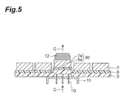
- Figures 1 , 2 , 3 , 4 and 5 are schematic cross-sectional views illustrating a preferred embodiment of a method for producing a semiconductor chip with an adhesive film of the present invention.
- the method for producing a semiconductor chip with an adhesive film according to this embodiment comprises a first step ( Figure 1 ) of forming a cut 21 which separates a semiconductor wafer 1 into a plurality of semiconductor chips on one side of the semiconductor wafer 1 (side on which a circuit is formed) to a depth D1 which is less than the thickness of the semiconductor wafer and deeper than a final finished thickness, a second step ( Figure 2 ) of preparing a divided semiconductor wafer 7 comprising a plurality of semiconductor chips by grinding the other side of the semiconductor wafer on which no cut is formed to the final finished thickness to reach the cut 21, a third step ( Figure 3 ) of preparing a laminate 20 in which the divided semiconductor wafer 7, an adhesive film 8 for a semiconductor according to the present invention and a dicing tape 3 are laminated in that order, and a fourth step
- a wafer composed of single crystalline silicon, polycrystalline silicon, various ceramics or compound semiconductors such as gallium arsenide is used as the semiconductor wafer 1.
- the semiconductor wafer 1 is laminated on the dicing tape 3, and the cut 21 is formed by half-cutting the surface (circuit side) of the semiconductor wafer by a dicing blade 4 to a depth deeper than the intended final finished thickness of the semiconductor chip as shown in Figure 1 .
- D1 is preferably 5 to 50 ⁇ m larger, more preferably 10 to 30 ⁇ m larger than the final finished thickness.
- a back grind tape 6 is attached to the side of the semiconductor wafer 1 prepared in the first step on which the cut 21 has been formed, and the side of the semiconductor wafer on which no cut is formed is thinned (back ground) by a back grinding wheel 5 of a back grinding apparatus so that the wafer reaches a predetermined thickness (final finished thickness) D2, thereby preparing the divided semiconductor wafer 7 composed of a plurality of semiconductor chips as shown in Figure 2 .
- Fully Automatic Grinder DFG8540 made by DISCO Corporation or the like, for example, may be used as the back grinding apparatus.
- Polyethylene terephthalate tapes or the like are used as the back grind tape 6.
- a laminate 20 is prepared by a method of attaching the adhesive film 8 for a semiconductor and the dicing tape 3 in that order to the back side of the divided semiconductor wafer 7 (the side opposite to the back grind tape 6 side), or a method of attaching a composite sheet in which the adhesive film 8 for a semiconductor and the dicing tape 3 are laminated on the back side of the divided semiconductor wafer 7 in such a direction that the adhesive film 8 for a semiconductor is on the side of the divided semiconductor wafer 7.
- Figure 3 illustrates a case where the back grind tape 6 is laminated on the divided semiconductor wafer 7.
- the back grind tape 6 will be peeled off before the next step.
- the dicing tape 3 of the laminate 20 shown in Figure 3 has a wafer ring 2 which is a fixing ring.
- Any tape may be used as the dicing tape 3 without particular limitation as long as it has enough adhesiveness to be fixed to the fixing ring and can be expanded to leave an appropriate space between each piece of the divided semiconductor wafer (a plurality of semiconductor chips) 7 upon picking up in the above-described fourth step.
- vinyl chloride tape may be used as the dicing tape.
- commercially available tapes include "AD-80H” and "T-80MW” (trade names, available from DENKI KAGAKU KOGYO K.K.).
- the bottom side of the expanded dicing tape 3 is vacuum sucked by a suction dome 11, and the portion where a semiconductor chip to be picked up is located is pushed up by a push-up needle 10, thereby picking up the semiconductor chip 7a by a pick-up collet 12 in the laminating direction of the laminate (the direction of arrow C in Figure 5 ).
- a shearing force acts in the thickness direction of the adhesive film 8 for a semiconductor, and the adhesive film 8 is divided in the shape of the semiconductor chip 7a. In this way, a semiconductor chip 30 with an adhesive film 8a laminated thereon in which flash is sufficiently little and which has substantially the same shape as that of the semiconductor chip is produced.
- pins are preferably disposed near and between the four corners of a chip at regular intervals.
- the suction effect from the bottom side of the dicing tape is decreased when too many pins are disposed, and therefore it is preferable to dispose about 9 pins if they have a size of about 10 mm ⁇ 10 mem.
- a pick-up collet 12 for picking up a semiconductor chip has substantially the same size as the chip.
- the push-up height is preferably up to 2000 ⁇ m or less, preferably 700 ⁇ m or less, more preferably 600 ⁇ m or less, and further preferably 500 ⁇ m or less. Pushing up to a height of more than 2000 ⁇ m is not preferred because the chip may be cracked.
- Pins are pushed up at a rate of preferably 20 to 200 mm/s, more preferably 30 to 150 mm/s and further preferably 50 to 100 mm/s. Pushing up at less than 20 mm/s is not preferred because dividing die-bonding film upon pushing up tends to become difficult.
- pushing up may be performed in two or more stages.
- pins may be pushed up under the conditions of a push-up height of 250 to 1000 ⁇ m and a push-up rate of 50 to 100 mm/s in the first stage, and under the conditions of a push-up height of 1000 to 2000 ⁇ m and a push-up rate of 1 to 30 mm/s in the second stage.
- the dicing tape 3 For expanding the dicing tape 3, by holding up an expand ring 9 from the bottom side of the dicing tape 3 (in the direction of arrow A in Figure 4 ), the dicing tape 3 is expanded in such a direction that each piece of the divided semiconductor wafer (a plurality of semiconductor chips) 7 is separated (in the direction of arrow B in Figure 4 ).
- the dicing tape 3 is expanded using a die bonder.
- the difference between the (maximum) width of the dicing tape 3 after expansion and the (maximum) initial width of the dicing tape 3 is preferably 1 to 20 mm, more preferably 2 to 15 mm, and further preferably 3 to 10 mm.
- the amount of expansion of the dicing tape 3 in this embodiment can be smaller than that when cutting a conventional adhesive film for a semiconductor by expansion. Therefore, it is unnecessary to use an additional expanding device.
- an adhesive film 8a in which flash is sufficiently little and which has substantially the same shape as that of the semiconductor chips is separated from the adhesive film for a semiconductor in the above-described pick-up step.
- the adhesive film for a semiconductor according to the present invention has a thickness in the range of 1 to 15 ⁇ m and a tensile elongation at break of less than 5%, and the tensile elongation at break is less than 110% of the elongation at the maximum load.
- Such an adhesive film for a semiconductor is composed of a thermosetting resin and/or a thermoplastic resin.
- an adhesive film for a semiconductor When the thickness of an adhesive film for a semiconductor is less than 1 ⁇ m, preparing the adhesive film becomes difficult, and when the thickness is more than 15 ⁇ m, dividing the adhesive film for a semiconductor by picking up of semiconductor chips becomes difficult.
- the adhesive film for a semiconductor has a tensile elongation at break of 5% or more, it is necessary to expand the dicing tape in a greater degree than usual.
- a ratio of a tensile elongation at break to the elongation at the maximum load of 110% or more means long duration of a yielded state or high possibility of the occurrence of necking. In such cases, completely dividing the adhesive film for a semiconductor with preventing flash from occurring becomes difficult, and so preparing an adhesive film suited to the shape of semiconductor chips becomes difficult.
- the adhesive film for a semiconductor has a tensile elongation at break of preferably less than 4%, more preferably less than 3.5%.
- the ratio of a tensile elongation at break to the elongation at the maximum load is preferably less than 108%, more preferably less than 105%. The ratio is the lowest, 100%, when the tensile elongation at break and the elongation at the maximum load are the same.
- the maximum stress, the elongation at the maximum load and the tensile elongation at break are measured by a tensile test at 25°C using a strip test piece having a width of 5 mm, a length of 50 mm and a thickness of 25 ⁇ m cut from a B-stage adhesive film for a semiconductor under the following conditions.
- Tensile tester 100N Autograph "AGS-100NH” made by Shimadzu Corporation Chuck distance (at start of test): 30 mm
- the maximum load, chuck distance at the maximum load and chuck distance at break are read from a stress-strain curve obtained in the tensile test, and using these values and the measured value of the cross-sectional area of a sample, the maximum stress, the elongation at the maximum load and the tensile elongation at break are calculated by the following formula.
- Maximum stress Pa maximum load N / cross sectional area m 2 of sample
- Elongation at maximum load % chuck distance mm at maximum load ⁇ 30 / 30 ⁇ 100
- Tensile elongation at break % chuck distance mm at break ⁇ 30 / 30 ⁇ 100
- a plurality of test pieces is subjected to measurement and the mean value is recorded as the tensile properties of the adhesive film for a semiconductor.
- the tensile test is preferably carried out under the above-described conditions in consideration of reproducibility, but they may be changed to other conditions which produce substantially the same test results.
- the adhesive film for a semiconductor has a thickness of preferably 3 to 15 ⁇ m, more preferably 5 to 15 ⁇ m in consideration of the adhesion to an adherend and separability of a film.
- the adhesive film 8 for a semiconductor preferably contains a high molecular weight component, a Thermosetting component and a filler.
- a high molecular weight component preferably contains a high molecular weight component, a Thermosetting component and a filler.
- the high molecular weight component constituting the adhesive film for a semiconductor preferably has a glass transition temperature (Tg) of 60°C or lower. Also, a high molecular weight component having a heat resistance of 300°C or higher is preferred. Examples of preferred high molecular weight components include polyimide resins, polyamide imide resins, phenoxy resins, acrylic resins, polyamide resins and urethane resins. These may be used alone or in combination of two or more. Of them, polyimide resins are particularly preferred. Using a polyimide resin allows the adhesive film 8 for a semiconductor to have the tensile properties as described above with maintaining a reasonably small filler content.
- Tg glass transition temperature
- a high molecular weight component having a heat resistance of 300°C or higher is preferred.
- preferred high molecular weight components include polyimide resins, polyamide imide resins, phenoxy resins, acrylic resins, polyamide resins and urethane resins. These may be used alone or in combination of two or
- Thermosetting components mean those which can be formed into a cured product by crosslinking by heating, and are composed of, for example, a thermosetting resin and a curing agent therefor.
- Thermosetting resins are not particularly limited and conventionally known resins may be used. Of them, in consideration of the convenience for peripheral materials of semiconductors (availability of high purity products, diversity of products and easily controllable reactivity), epoxy resins and imide compounds having at least 2 thermosetting imide groups in a molecule are preferred. Epoxy resins are generally used together with an epoxy resin curing agent.
- Epoxy resins preferably contain 2 or more epoxy groups.
- phenol glycidyl ether epoxy resins are preferred.
- examples of phenol glycidyl ether epoxy resins include condensates of bisphenol A, bisphenol AD, bisphenol S, bisphenol F or halogenated bisphenol A and epichlorohydrin, glycidyl ether of phenol novolac resin, glycidyl ether of cresol novolac resin and glycidyl ether of bisphenol A novolac resin.
- novolac epoxy resins are preferred because their cured products have a high crosslinking density and the adhesion strength can be increased upon heating of the film. These may be used alone or in combination of two or more.
- epoxy resin curing agents include phenol compounds, aliphatic amines, alicyclic amines, aromatic polyamines, polyamides, aliphatic acid anhydrides, alicyclic acid anhydrides, aromatic acid anhydrides, dicyandiamides, organic acid dihydrazides, boron trifluoride amine complexes, imidazoles and tertiary amines.
- phenol compounds are preferred, and phenol compounds having two or more phenolic hydroxyl groups are particularly preferred. More specifically, naphthol novolac resin and trisphenol novolac resin are preferred. Using these phenol compounds as an epoxy resin curing agent makes it possible to effectively reduce contamination on chip surfaces and devices upon heating for package assembly and the generation of outgas that causes odor.
- the tensile properties of the adhesive film for a semiconductor can be controlled by adjusting the content of filler.
- the higher the content of filler the smaller the tensile elongation at break may be and the smaller the ratio of the tensile elongation at break to the elongation at the maximum load may be.
- using an appropriate amount of filler can produce advantages of improving handling properties and thermal conductivity, adjusting melt viscosity and achieving thixatropic properties.
- the filler is preferably an inorganic filler. More specifically, an inorganic filler containing at least one inorganic material selected from the group consisting of aluminum hydroxide, magnesium hydroxide, calcium carbonate, magnesium carbonate, calcium silicate, magnesium silicate, calcium oxide, magnesium oxide, alumina, aluminum nitride, aluminum borate whiskers, boron nitride, crystalline silica, amorphous silica and antimony oxide is preferred. Of them, to improve thermal conductivity, alumina, aluminum nitride, boron nitride, crystalline silica and amorphous silica are preferred.
- aluminum hydroxide, magnesium hydroxide, calcium carbonate, magnesium carbonate, calcium silicate, magnesium silicate, calcium oxide, magnesium oxide, alumina, crystalline silica and amorphous silica are preferred.
- alumina, silica, aluminum hydroxide and antimony oxide are preferred.
- a plurality of fillers may be used in combination.
- breaking may easily occur between an adherend such as an organic substrate having irregularities on the surface and a semiconductor chip upon reflow.
- a higher content of filler may cause a decrease in the resistance in a reliability test in high-temperature high-humidity environment such as a HAST test.
- a higher content of filler may also increase the temperature at which an adhesive film for a semiconductor can be attached to a semiconductor wafer.
- the content of the filler is preferably less than 30% by mass, more preferably less than 25% by mass, and further preferably less than 20% by mass based on the total mass of the adhesive film for a semiconductor.
- the adhesive film 8 for a semiconductor can be attached to the adherend semiconductor wafer at a temperature of 100°C or lower. If the peel strength at the interface between an adhesive film for a semiconductor and a semiconductor wafer is 20 N/m or more when the adhesive film for a semiconductor kept at a predetermined temperature is attached to the semiconductor wafer, the adhesive film for a semiconductor is considered to be attachable to the semiconductor wafer.
- the adhesive film for a semiconductor is attached to a semiconductor wafer using, for example, a hot roll laminator set at a temperature of 100°C or lower.
- the peel strength is measured in an atmosphere of 25°C at a tensile angle of 90° and a tensile rate of 50 mm/minute.
- An adhesive film for a semiconductor which can be attached to a semiconductor wafer at 100°C or lower can be prepared by, for example, reducing the content of the filler or using a thermoplastic resin having a low Tg.
- the temperature at which an adhesive film 8 for a semiconductor can be attached to a semiconductor wafer is preferably 95°C or lower, more preferably 90°C or lower.
- the adhesive film 8 for a semiconductor can be attached to the adherend semiconductor wafer at a temperature of preferably 80°C or lower.
- the adhesive film 8 for a semiconductor preferably has heat resistance and humidity resistance required when mounting a semiconductor chip on a semiconductor chip mounting support member. To this end, it is preferred that the adhesive film 8 for a semiconductor has passed a reflow crack resistance test.
- the reflow crack resistance of the adhesive film for a semiconductor can be evaluated based on adhesion strength.
- the peel strength when bonding an adhesive film for a semiconductor to a semiconductor wafer at an adhesion area of 4 ⁇ 2 mm is preferably 1.0 kg/cm or more at an initial stage and 0.5 kg/cm or more after allowing to stand in an atmosphere at 85°C/85% for 48 hours.
- the initial peel strength is more preferably 1.3 kg/cm or more, and further preferably 1.5 kg/cm.
- the peel strength after allowing to stand in an atmosphere at 85°C/85% for 48 hours is more preferably 0.7 kg/cm or more, and further preferably 0.8 kg/cm or more.
- the adhesive film 8 for a semiconductor may be prepared by a method in which a coating solution containing a high molecular weight component such as a thermoplastic resin, a thermosetting component, a filler and an organic solvent in which they are dissolved or dispersed is applied to a base film, and the organic solvent is removed from the coating solution on the base film by heating.
- a coating solution containing a high molecular weight component such as a thermoplastic resin, a thermosetting component, a filler and an organic solvent in which they are dissolved or dispersed is applied to a base film, and the organic solvent is removed from the coating solution on the base film by heating.
- Organic solvents are not particularly limited as long as materials can be homogeneously dissolved or dispersed in them.
- Examples thereof include dimethylformamide, dimethylacetamide, N-methylpyrrolidone, dimethyl sulfoxide, diethylene glycol dimethyl ether, toluene, benzene, xylene, methyl ethyl ketone, tetrahydrofuran, ethyl cellosolve, ethyl cellasolve acetate, butyl cellosolve, dioxane, cyclohexanone and ethyl acetate. These may be used alone or in combination of two or more.
- Base films are not particularly limited as long as they can withstand heating for removing organic solvents.
- Examples of base films include polyester films, polypropylene films, polyethylene terephthalate films, polyimide films, polyetherimide films, polyether naphthalate films and methyl pentene films. Multilayer films composed of two or more of these films in combination may also be used as a base film.
- the surface of the base film may be treated with a silicone or silica release agent. After removing the organic solvent, the base film may not be removed but used as a support for an adhesive film for a semiconductor.
- the adhesive film for a semiconductor may be preserved or used in the form of a composite sheet with a dicing tape laminated thereon. Using such a composite sheet makes it possible to simplify the process of producing semiconductor devices.
- the adhesive film for a semiconductor used in the method for producing a semiconductor chip with an adhesive film of the present invention may be those prepared as a die bonding film having the following structure.
- the adhesive layers of the die bonding films (a) and (b) and the pressure-sensitive adhesive/adhesive layer of the die bonding film (c) correspond to the adhesive film for a semiconductor according to the present invention.
- a laminate according to the present invention can be prepared by either of the following methods.
- the adhesive layer of the above-described die bonding film (a) and a semiconductor wafer are laminated.
- the base material of the die bonding film is peeled off.
- a pressure-sensitive adhesive layer of a dicing tape material having the pressure-sensitive adhesive layer and a base material in that order is laminated on the adhesive layer.
- a laminate according to the present invention can be prepared by the following method.
- a laminate can be prepared by this procedure when the base material and the pressure-sensitive adhesive layer function as a dicing tape.
- a laminate may also be prepared by laminating a dicing tape on the pressure-sensitive adhesive layer after peeling off the base material.
- a laminate according to the present invention can be prepared by the following method.
- the pressure-sensitive adhesive/adhesive layer of the above-described die bonding film (c) and a semiconductor wafer are laminated.
- a laminate can be prepared by this procedure when the base material functions as a dicing tape.
- a laminate may also be prepared by laminating a dicing tape on the pressure-sensitive adhesive layer after peeling off the base material.
- the present invention can also provide a method for producing a semiconductor chip with an adhesive film comprising steps of: preparing a laminate in which at least a divided semiconductor wafer comprising a plurality of semiconductor chips, obtained by forming a cut which separates the semiconductor wafer into a plurality of semiconductor chips on one side of the semiconductor wafer in a thickness less than that of the semiconductor wafer and by grinding the other side of the semiconductor wafer on which no cut is formed to reach the cut, a film-form pressure-sensitive adhesive/adhesive and a base material are laminated, the film-form pressure-sensitive adhesive/adhesive having a thickness in the range of 1 to 15 ⁇ m and a tensile elongation at break of less than 5%, and the tensile elongation at break being less than 110% of the elongation at a maximum load; and dividing the film-form pressure-sensitive adhesive/adhesive by picking up the plurality
- the method for producing a semiconductor chip with an adhesive film of the present invention can also be applied to a process in which an adhesive film for a semiconductor is attached to the circuit side of a semiconductor wafer.
- the semiconductor chip 30 with an adhesive film prepared by the method according to this embodiment as described above constitutes a semiconductor element such as an IC and an LSI.
- the semiconductor chip 30 with an adhesive film is bonded to another semiconductors chip or a semiconductor chip mounting support member via the adhesive film 8a.
- Examples of semiconductor chip mounting support members include lead frames such as 42 alloy lead frames and copper lead frames, a resin film composed of an epoxy resin, a polyimide resin or a maleimide resin, substrates prepared by impregnating nonwoven glass fabric or woven glass fabric with a thermosetting resin such as an epoxy resin, a polyimide resin or a maleimide resin and curing the resultant, and glass substrates and ceramic substrates such as alumina.
- FIG. 6 is a cross-sectional view illustrating an embodiment of a semiconductor device prepared by the above method.
- a semiconductor device 100 shown in Figure 6 has a wiring board (support member) 13 and the semiconductor chip 7a bonded to the wiring board 13 via the adhesive film 8a.
- the semiconductor chip 7a is connected to the wiring of the wiring board 13 by means of a binding wire 14.
- the semiconductor chip 7a is sealed by a sealing resin layer 15 in which the chips are embedded.
- a semiconductor chip and a support member, or semiconductor chips with each other, are bonded by heating at 60 to 300°C for 0.1 to 300 seconds with an adhesive film for a semiconductor interposed between the semiconductor chip and the support member or between the semiconductor chips.
- the adhesive film 8 for a semiconductor contains a thermosetting resin
- the semiconductor chip after bonding is preferably heated to facilitate adhesion of the adhesive film for a semiconductor to an adherend or its curing, so as to increase the strength of the bond. Heating conditions may be adjusted based on the composition of the adhesive film, and the semiconductor chip is heated generally at 60 to 220°C for 0.1 to 600 minutes. When sealed with a resin, the heating in the step of curing the sealing resin may be utilized.
- a 500 ml four-neck flask equipped with a thermometer, a stirrer and a calcium chloride drying tube was charged with diamines, i.e., 1,3-bis(3-aminopropyl)tetramethyldisiloxane (0.06 mol) and 4,9-dioxadecane-1,12-diamine (0.04 mol), and 150 g of N-methyl-2-pyrrolidone as a solvent, and the mixture was stirred at 60°C to dissolve diamines.
- diamines i.e., 1,3-bis(3-aminopropyl)tetramethyldisiloxane (0.06 mol) and 4,9-dioxadecane-1,12-diamine (0.04 mol
- a boron nitride filler available from MIZUSHIMA FERROALLOY CO., LTD.
- Aerosil filler R972 available from Nippon Aerosil Co., Ltd.
- the varnish prepared was applied to a release-treated polyethylene terephthalate film (film As having a thickness of 50 ⁇ m available from Teijin DuPont Films Japan Limited) and the resultant was heated at 80°C for 30 minutes and then at 120°C for 30 minutes to give an adhesive film for a semiconductor having a thickness of 5 ⁇ m.
- a varnish prepared in the same manner as in Example 1 was applied to a release-treated polyethylene terephthalate film (film A31 having a thickness of 50 ⁇ m available from Teijin DuPont Films Japan Limited) and the resultant was heated at 80°C for 30 minutes and then at 120°C for 30 minutes to give an adhesive film for a semiconductor having a thickness of 15 ⁇ m.
- a varnish prepared in the same manner as in Example 1 was applied to a release-treated polyethylene terephthalate film (film A31 having a thickness of 50 ⁇ m available from Teijin DuPont Films Japan Limited) and the resultant was heated at 80°C for 30 minutes and then at 120°C for 30 minutes to give an adhesive film for a semiconductor having a thickness of 25 ⁇ m.
- DF-402 (available from Hitachi Chemical Co., Ltd., trade name, thickness: 15 ⁇ m) was prepared as an adhesive film for a semiconductor of Comparative Example 2.
- a tensile test was performed using a strip test piece (having a width of 5 mm and a length of 50 mm) cut from a B-stage adhesive film.
- the maximum stress, elongation at the maximum load and tensile elongation at break were calculated from the stress-strain curve obtained based on the following calculation formulas.
- the tensile test was performed using a tensile tester (100N Autograph AGS-100NH made by Shimadzu Corporation) in an atmosphere of 25°C under the conditions of a chuck distance at the start of the test of 30 mm and a tensile rate of 5 mm/minute.
- Tensile elongation at break % chuck distance mm at break ⁇ 30 / 30 ⁇ 100
- a 50 ⁇ m-thick semiconductor wafer (material: single crystalline silicon) was divided into semiconductor chips having a thickness of 50 ⁇ m and a size of 10 mm ⁇ 10 mm by means of the dicing-before-grinding shown in Figures 1 and 2 .
- the adhesive films for a semiconductor prepared in Examples and Comparative Examples were each cut out into a circle having a diameter of 210 mm, and the resulting adhesive films for a semiconductor were each laminated on a dicing tape (available from DENKI KAGAKU KOGYO KABUSHIKI KAISHA, trade name "AD-80H", thickness: 80 ⁇ m) using a wafer mounter "DM-300H" (made by JCM Co., Ltd., trade name) under the conditions of room temperature, a linear pressure of 5 kgf and 10 mm/s to give a laminated product of the adhesive film for a semiconductor and the dicing tape. A wafer ring was also attached to the dicing tape of the laminated product.
- the above-described laminated product of the adhesive film for a semiconductor and the dicing tape was attached to the back side of the above-described divided semiconductor wafer which had been subjected to dicing-before-grinding using a wafer mounter "DM-300H" (made by JCM Co., Ltd., trade name) under the conditions of a hot plate temperature of 80°C, a linear pressure of 5 kgf and 3 mm/s to prepare a sample laminate.
- DM-300H made by JCM Co., Ltd., trade name
- the sample laminate prepared above was set on flexible die bonder "B-730" (made by Renesas Eastern Japan Semiconductor, Inc., trade name) and the dicing tape was expanded by the expanding device.
- the rate of expansion was 10 mm/s and the amount of expansion was 4 mm.
- the semiconductor chips in the expanded sample laminate were picked up using the multi-pin push-up jig of flexible bonder "DB-730" (made by Renesas Eastern Japan Semiconductor, Inc.) in which 9 ejector needles (made by Micro-Mechanics Pte Ltd., SEN-83-05, needle diameter: 0.7 mm, tip: semicircular, 350 ⁇ m in diameter) are arranged in a grid pattern at an interval of 4.2 mm while pushing up the needles and using a rubber chip (made by Micro-Mechanics Pte Ltd., trade name: 13-087E-33, 10 mm ⁇ 10 mm) as a pick-up collet.
- DB-730 made by Renesas Eastern Japan Semiconductor, Inc.
- 9 ejector needles made by Micro-Mechanics Pte Ltd., SEN-83-05, needle diameter: 0.7 mm, tip: semicircular, 350 ⁇ m in diameter
- a rubber chip made by Micro-
- the semiconductor chips were picked up while pushing up the needles in two stages; they were pushed up under the conditions of a push-up height of 300 ⁇ m and a push-up rate of 89.4 mmls in the first stage, and under the conditions of a push-up height of 1,500 ⁇ m and a push-up rate of 8.94 mm/s in the second stage for a holding time after pushing up (pick-up time) of 500 ms.
- Pick-up properties in this experiment were evaluated based on the following criteria.
- the method for producing a semiconductor chip with an adhesive film using an adhesive film for a semiconductor of the present invention is capable of producing a semiconductor chip with an adhesive film laminated thereon in which flash is sufficiently little and which has substantially the same shape as that of the semiconductor chip, and capable of achieving both assembling properties and reliability in a method of producing a semiconductor device based on a dicing-before-grinding process.
- the present invention can provide a method for producing a semiconductor chip with an adhesive film, capable of producing a semiconductor chip from a semiconductor wafer at a good yield and capable of producing a semiconductor chip with an adhesive film laminated thereon in which flash is sufficiently little and which has substantially the same shape as that of the semiconductor chip, an adhesive film for a semiconductor suitably used in the method for producing a semiconductor chip with an adhesive film and a method for producing a semiconductor device capable of achieving both assembling properties and reliability.
Landscapes
- Adhesive Tapes (AREA)
- Die Bonding (AREA)
- Dicing (AREA)
- Adhesives Or Adhesive Processes (AREA)
Applications Claiming Priority (2)
| Application Number | Priority Date | Filing Date | Title |
|---|---|---|---|
| JP2007263347 | 2007-10-09 | ||
| PCT/JP2008/068237 WO2009048061A1 (fr) | 2007-10-09 | 2008-10-07 | Procédé de fabrication de puce de semi-conducteur avec film adhésif, film adhésif pour semi-conducteur utilisé dans le procédé, et procédé de fabrication de dispositif semi-conducteur |
Publications (2)
| Publication Number | Publication Date |
|---|---|
| EP2200074A1 true EP2200074A1 (fr) | 2010-06-23 |
| EP2200074A4 EP2200074A4 (fr) | 2011-12-07 |
Family
ID=40549205
Family Applications (1)
| Application Number | Title | Priority Date | Filing Date |
|---|---|---|---|
| EP08837752A Withdrawn EP2200074A4 (fr) | 2007-10-09 | 2008-10-07 | Procédé de fabrication de puce de semi-conducteur avec film adhésif, film adhésif pour semi-conducteur utilisé dans le procédé, et procédé de fabrication de dispositif semi-conducteur |
Country Status (8)
| Country | Link |
|---|---|
| US (2) | US8198176B2 (fr) |
| EP (1) | EP2200074A4 (fr) |
| JP (2) | JP5353703B2 (fr) |
| KR (2) | KR20120007556A (fr) |
| CN (1) | CN101821834A (fr) |
| MY (1) | MY151700A (fr) |
| TW (1) | TWI473152B (fr) |
| WO (1) | WO2009048061A1 (fr) |
Cited By (3)
| Publication number | Priority date | Publication date | Assignee | Title |
|---|---|---|---|---|
| WO2013056936A1 (fr) * | 2011-10-19 | 2013-04-25 | Ams Ag | Procédé pour fabriquer des composants semi-conducteurs de faible épaisseur |
| DE102015100827A1 (de) * | 2015-01-21 | 2016-07-21 | Infineon Technologies Ag | Verfahren zum Bearbeiten eines Halbleitersubstrats und Halbleiterchips |
| WO2026030111A1 (fr) * | 2024-07-31 | 2026-02-05 | Texas Instruments Incorporated | Isolation pour puce sur dispositif conducteur et procédé de fabrication |
Families Citing this family (38)
| Publication number | Priority date | Publication date | Assignee | Title |
|---|---|---|---|---|
| US8198176B2 (en) * | 2007-10-09 | 2012-06-12 | Hitachi Chemical Company, Ltd. | Method for producing semiconductor chip with adhesive film, adhesive film for semiconductor used in the method, and method for producing semiconductor device |
| CN102947929B (zh) * | 2010-04-19 | 2016-05-18 | 日东电工株式会社 | 倒装芯片型半导体背面用膜 |
| JP5323779B2 (ja) * | 2010-07-26 | 2013-10-23 | 古河電気工業株式会社 | ウエハ加工用テープ |
| JP5580701B2 (ja) * | 2010-09-13 | 2014-08-27 | 日東電工株式会社 | ダイシング・ダイボンドフィルム |
| JP5883250B2 (ja) * | 2011-07-29 | 2016-03-09 | リンテック株式会社 | 転写装置および転写方法 |
| JP2013065757A (ja) * | 2011-09-20 | 2013-04-11 | Toshiba Corp | 半導体チップのピックアップ方法及び半導体チップのピックアップ装置 |
| KR101924049B1 (ko) * | 2011-11-02 | 2018-12-03 | 헨켈 아이피 앤드 홀딩 게엠베하 | 전자 부품용 접착제 |
| JP6034384B2 (ja) * | 2012-08-23 | 2016-11-30 | リンテック株式会社 | 保護膜形成層付ダイシングシートおよびチップの製造方法 |
| JP5480415B1 (ja) * | 2012-10-11 | 2014-04-23 | 古河電気工業株式会社 | 半導体ウェハ加工用粘着テープ |
| KR101994930B1 (ko) | 2012-11-05 | 2019-07-01 | 삼성전자주식회사 | 일체형 단위 반도체 칩들을 갖는 반도체 패키지 |
| US9484260B2 (en) * | 2012-11-07 | 2016-11-01 | Semiconductor Components Industries, Llc | Heated carrier substrate semiconductor die singulation method |
| US9136173B2 (en) * | 2012-11-07 | 2015-09-15 | Semiconductor Components Industries, Llc | Singulation method for semiconductor die having a layer of material along one major surface |
| KR20140123129A (ko) | 2013-04-10 | 2014-10-22 | 삼성전자주식회사 | 반도체 패키지 |
| US20160086908A1 (en) * | 2013-05-28 | 2016-03-24 | Lintec Corporation | Adhesive agent composition, adhesive sheet, and method for manufacturing semiconductor device |
| KR102474242B1 (ko) * | 2015-01-09 | 2022-12-06 | 삼성전자주식회사 | 반도체 패키지 및 그 제조 방법 |
| SG10201907601SA (en) * | 2015-03-04 | 2019-10-30 | Lintec Corp | Film-like adhesive composite sheet and method for manufacturing semiconductor device |
| DE102015204698B4 (de) | 2015-03-16 | 2023-07-20 | Disco Corporation | Verfahren zum Teilen eines Wafers |
| US9633883B2 (en) | 2015-03-20 | 2017-04-25 | Rohinni, LLC | Apparatus for transfer of semiconductor devices |
| WO2016189986A1 (fr) * | 2015-05-25 | 2016-12-01 | リンテック株式会社 | Procédé de fabrication de dispositif à semi-conducteur |
| FR3042906B1 (fr) * | 2015-10-23 | 2018-07-27 | Commissariat Energie Atomique | Procede d’amincissement d’echantillons |
| JP2017117959A (ja) * | 2015-12-24 | 2017-06-29 | リンテック株式会社 | 半導体ウエハの加工方法、半導体チップの製造方法及び加工半導体ウエハ |
| WO2017145979A1 (fr) * | 2016-02-23 | 2017-08-31 | リンテック株式会社 | Feuille composite adhésive en forme de film et procédé de production d'un dispositif semi-conducteur |
| US10141215B2 (en) | 2016-11-03 | 2018-11-27 | Rohinni, LLC | Compliant needle for direct transfer of semiconductor devices |
| US10504767B2 (en) | 2016-11-23 | 2019-12-10 | Rohinni, LLC | Direct transfer apparatus for a pattern array of semiconductor device die |
| US10471545B2 (en) | 2016-11-23 | 2019-11-12 | Rohinni, LLC | Top-side laser for direct transfer of semiconductor devices |
| WO2018180594A1 (fr) | 2017-03-28 | 2018-10-04 | リンテック株式会社 | Feuille composite adhésive du type film et procédé de fabrication d'un dispositif semi–conducteur |
| JP6912254B2 (ja) * | 2017-04-05 | 2021-08-04 | 株式会社ディスコ | 加工方法 |
| US10373869B2 (en) | 2017-05-24 | 2019-08-06 | Semiconductor Components Industries, Llc | Method of separating a back layer on a substrate using exposure to reduced temperature and related apparatus |
| GB201801457D0 (en) * | 2018-01-30 | 2018-03-14 | Pragmatic Printing Ltd | Integrated circuit manufacturing process and apparatus |
| JP7214306B2 (ja) * | 2018-04-27 | 2023-01-30 | 株式会社ディスコ | 被加工物の加工方法 |
| US10410905B1 (en) * | 2018-05-12 | 2019-09-10 | Rohinni, LLC | Method and apparatus for direct transfer of multiple semiconductor devices |
| WO2020004210A1 (fr) * | 2018-06-29 | 2020-01-02 | リンテック株式会社 | Méthode de production de puce semi-conductrice et méthode de production de dispositif semi-conducteur |
| US12142549B2 (en) * | 2018-07-03 | 2024-11-12 | Texas Instruments Incorporated | Wafer stencil for controlling die attach material thickness on die |
| US11094571B2 (en) | 2018-09-28 | 2021-08-17 | Rohinni, LLC | Apparatus to increase transferspeed of semiconductor devices with micro-adjustment |
| JP7427480B2 (ja) * | 2020-03-09 | 2024-02-05 | キオクシア株式会社 | 半導体装置 |
| JP7446887B2 (ja) | 2020-03-30 | 2024-03-11 | リンテック株式会社 | フィルム状接着剤 |
| CN115443524A (zh) * | 2020-04-23 | 2022-12-06 | 三井化学东赛璐株式会社 | 背面研磨用粘着性膜及电子装置的制造方法 |
| MY198402A (en) * | 2020-12-17 | 2023-08-28 | Inari Tech Sdn Bhd | A Method For Fabricating Semiconductor Articles And System Thereof |
Family Cites Families (41)
| Publication number | Priority date | Publication date | Assignee | Title |
|---|---|---|---|---|
| US5903046A (en) * | 1996-02-20 | 1999-05-11 | Micron Technology, Inc. | Integrated circuit device having cyanate ester buffer coat |
| JP3410371B2 (ja) * | 1998-08-18 | 2003-05-26 | リンテック株式会社 | ウエハ裏面研削時の表面保護シートおよびその利用方法 |
| JP3816253B2 (ja) * | 1999-01-19 | 2006-08-30 | 富士通株式会社 | 半導体装置の製造方法 |
| DE19962763C2 (de) * | 1999-07-01 | 2001-07-26 | Fraunhofer Ges Forschung | Verfahren zum Vereinzeln eines Wafers |
| TWI299748B (en) * | 2000-02-15 | 2008-08-11 | Hitachi Chemical Co Ltd | Adhesive composition, its manufacturing method, and adhesive film, substrate for carrying a semiconductor device and semiconductor device using such adhesive composition |
| JP2002016021A (ja) | 2000-06-28 | 2002-01-18 | Toshiba Corp | 半導体チップの生産方法及び半導体チップ |
| JP3485525B2 (ja) * | 2000-07-06 | 2004-01-13 | 沖電気工業株式会社 | 半導体装置の製造方法 |
| JP2002043251A (ja) * | 2000-07-25 | 2002-02-08 | Fujitsu Ltd | 半導体装置の製造方法及び半導体装置 |
| JP2002160211A (ja) | 2000-11-27 | 2002-06-04 | Murata Mfg Co Ltd | 積層セラミック電子部品の製造方法 |
| JP4708577B2 (ja) * | 2001-01-31 | 2011-06-22 | キヤノン株式会社 | 薄膜半導体装置の製造方法 |
| JP3544362B2 (ja) * | 2001-03-21 | 2004-07-21 | リンテック株式会社 | 半導体チップの製造方法 |
| JP2002367933A (ja) | 2001-06-11 | 2002-12-20 | Disco Abrasive Syst Ltd | 半導体ウェーハの分離方法 |
| JP4330821B2 (ja) * | 2001-07-04 | 2009-09-16 | 株式会社東芝 | 半導体装置の製造方法 |
| US6790524B2 (en) * | 2001-08-02 | 2004-09-14 | Toray Plastics (America), Inc. | Biaxially oriented polypropylene metallized film for packaging |
| WO2003028072A1 (fr) * | 2001-09-20 | 2003-04-03 | Renesas Technology Corp. | Procede de fabrication de dispositif semi-conducteur |
| KR101177251B1 (ko) * | 2003-06-06 | 2012-08-24 | 히다치 가세고교 가부시끼가이샤 | 접착시트, 다이싱 테이프 일체형 접착시트 및 반도체 장치의 제조방법 |
| JP2005019525A (ja) * | 2003-06-24 | 2005-01-20 | Disco Abrasive Syst Ltd | 半導体チップの製造方法 |
| JP4406300B2 (ja) | 2004-02-13 | 2010-01-27 | 株式会社東芝 | 半導体装置及びその製造方法 |
| KR100555559B1 (ko) * | 2004-03-03 | 2006-03-03 | 삼성전자주식회사 | 백 그라인딩 공정용 표면 보호 테이프를 이용하여 다이싱공정을 수행하는 반도체 장치의 제조 방법 |
| MY138566A (en) * | 2004-03-15 | 2009-06-30 | Hitachi Chemical Co Ltd | Dicing/die bonding sheet |
| WO2005112091A1 (fr) * | 2004-05-18 | 2005-11-24 | Hitachi Chemical Co., Ltd. | Feuille de liaison adhésive, dispositif semi-conducteur utilisant ladite feuille et procede de fabrication dudit dispositif semi-conducteur |
| JP2006086509A (ja) * | 2004-08-17 | 2006-03-30 | Denso Corp | 半導体基板の分断方法 |
| US7550367B2 (en) * | 2004-08-17 | 2009-06-23 | Denso Corporation | Method for separating semiconductor substrate |
| JP4624813B2 (ja) * | 2005-01-21 | 2011-02-02 | ルネサスエレクトロニクス株式会社 | 半導体装置の製造方法および半導体製造装置 |
| JP2006203133A (ja) | 2005-01-24 | 2006-08-03 | Lintec Corp | チップ体の製造方法、デバイスの製造方法およびチップ体固着用粘接着シート |
| JP4630692B2 (ja) * | 2005-03-07 | 2011-02-09 | 株式会社ディスコ | レーザー加工方法 |
| DE102005024431B4 (de) * | 2005-05-24 | 2009-08-06 | Infineon Technologies Ag | Verfahren zur Herstellung von Halbleiterbauteilen unter Verwendung einer Trägerplatte mit doppelseitig klebender Klebstofffolie |
| JP2007019151A (ja) | 2005-07-06 | 2007-01-25 | Furukawa Electric Co Ltd:The | ウエハ加工用テープおよびそれを用いたチップの製造方法 |
| JP4285455B2 (ja) * | 2005-07-11 | 2009-06-24 | パナソニック株式会社 | 半導体チップの製造方法 |
| JP4721834B2 (ja) * | 2005-09-06 | 2011-07-13 | 日東電工株式会社 | 粘着シート及びこの粘着シートを用いた製品の加工方法 |
| JP2007250598A (ja) * | 2006-03-14 | 2007-09-27 | Renesas Technology Corp | 半導体装置の製造方法 |
| JP5275553B2 (ja) * | 2006-06-27 | 2013-08-28 | スリーエム イノベイティブ プロパティズ カンパニー | 分割チップの製造方法 |
| WO2008010547A1 (fr) * | 2006-07-19 | 2008-01-24 | Sekisui Chemical Co., Ltd. | Ruban de découpage de puce liant et procédé de fabrication de puce semi-conductrice |
| JP2008186959A (ja) * | 2007-01-29 | 2008-08-14 | Toyoda Gosei Co Ltd | Iii−v族半導体素子、およびその製造方法 |
| US8232185B2 (en) * | 2007-04-05 | 2012-07-31 | Hitachi Chemical Company, Ltd. | Method for manufacturing semiconductor chip, adhesive film for semiconductor, and composite sheet using the film |
| CN102709201A (zh) * | 2007-04-06 | 2012-10-03 | 日立化成工业株式会社 | 半导体用粘接膜、复合片及使用它们的半导体芯片的制造方法 |
| US8198176B2 (en) * | 2007-10-09 | 2012-06-12 | Hitachi Chemical Company, Ltd. | Method for producing semiconductor chip with adhesive film, adhesive film for semiconductor used in the method, and method for producing semiconductor device |
| EP2200075A4 (fr) * | 2007-10-09 | 2011-12-07 | Hitachi Chemical Co Ltd | Procede de fabrication d'une puce de semi-conducteur avec film adhesif, film adhesif pour semi-conducteur utilise dans le procede, et procede de fabrication de dispositif semi-conducteur |
| KR101191121B1 (ko) * | 2007-12-03 | 2012-10-15 | 주식회사 엘지화학 | 다이싱 다이본딩 필름 및 다이싱 방법 |
| JP4717085B2 (ja) * | 2008-01-18 | 2011-07-06 | 日東電工株式会社 | ダイシング・ダイボンドフィルム |
| JP5561949B2 (ja) * | 2009-04-08 | 2014-07-30 | 日東電工株式会社 | 熱硬化型ダイボンドフィルム |
-
2008
- 2008-10-07 US US12/682,254 patent/US8198176B2/en active Active
- 2008-10-07 JP JP2009537000A patent/JP5353703B2/ja active Active
- 2008-10-07 WO PCT/JP2008/068237 patent/WO2009048061A1/fr not_active Ceased
- 2008-10-07 MY MYPI20101579 patent/MY151700A/en unknown
- 2008-10-07 KR KR1020117031361A patent/KR20120007556A/ko not_active Ceased
- 2008-10-07 EP EP08837752A patent/EP2200074A4/fr not_active Withdrawn
- 2008-10-07 CN CN200880110828A patent/CN101821834A/zh active Pending
- 2008-10-07 KR KR1020107008476A patent/KR101176431B1/ko active Active
- 2008-10-09 TW TW97138934A patent/TWI473152B/zh active
-
2012
- 2012-05-18 US US13/475,753 patent/US20120295400A1/en not_active Abandoned
-
2013
- 2013-04-08 JP JP2013080657A patent/JP2013179317A/ja active Pending
Cited By (6)
| Publication number | Priority date | Publication date | Assignee | Title |
|---|---|---|---|---|
| WO2013056936A1 (fr) * | 2011-10-19 | 2013-04-25 | Ams Ag | Procédé pour fabriquer des composants semi-conducteurs de faible épaisseur |
| US9105645B2 (en) | 2011-10-19 | 2015-08-11 | Ams Ag | Method for producing thin semiconductor components |
| DE102015100827A1 (de) * | 2015-01-21 | 2016-07-21 | Infineon Technologies Ag | Verfahren zum Bearbeiten eines Halbleitersubstrats und Halbleiterchips |
| US9831127B2 (en) | 2015-01-21 | 2017-11-28 | Infineon Technologies Ag | Method of processing a semiconductor substrate and semiconductor chip |
| DE102015100827B4 (de) | 2015-01-21 | 2024-10-02 | Infineon Technologies Ag | Verfahren zum Bearbeiten eines Halbleitersubstrats |
| WO2026030111A1 (fr) * | 2024-07-31 | 2026-02-05 | Texas Instruments Incorporated | Isolation pour puce sur dispositif conducteur et procédé de fabrication |
Also Published As
| Publication number | Publication date |
|---|---|
| TW200924047A (en) | 2009-06-01 |
| KR101176431B1 (ko) | 2012-08-30 |
| US20100311227A1 (en) | 2010-12-09 |
| EP2200074A4 (fr) | 2011-12-07 |
| JP2013179317A (ja) | 2013-09-09 |
| US8198176B2 (en) | 2012-06-12 |
| KR20120007556A (ko) | 2012-01-20 |
| MY151700A (en) | 2014-06-30 |
| KR20100061557A (ko) | 2010-06-07 |
| JPWO2009048061A1 (ja) | 2011-02-17 |
| JP5353703B2 (ja) | 2013-11-27 |
| WO2009048061A1 (fr) | 2009-04-16 |
| US20120295400A1 (en) | 2012-11-22 |
| TWI473152B (zh) | 2015-02-11 |
| CN101821834A (zh) | 2010-09-01 |
Similar Documents
| Publication | Publication Date | Title |
|---|---|---|
| US8198176B2 (en) | Method for producing semiconductor chip with adhesive film, adhesive film for semiconductor used in the method, and method for producing semiconductor device | |
| US8071465B2 (en) | Method for producing semiconductor chip with adhesive film, adhesive film for semiconductor used in the method, and method for producing semiconductor device | |
| KR101162819B1 (ko) | 반도체 칩의 제조방법, 및 반도체용 접착 필름 및 이것을 이용한 복합 시트 | |
| JP2025107273A (ja) | フィルム状接着剤、接着シート、並びに半導体装置及びその製造方法 | |
| JP5564782B2 (ja) | 接着剤組成物、フィルム状接着剤、接着シート及び半導体装置 | |
| JP2010001453A (ja) | 接着フィルム、接着シート、半導体装置及び半導体装置の製造方法 | |
| JP5374983B2 (ja) | 半導体装置の製造方法 | |
| WO2024189855A1 (fr) | Adhésif en forme de film, film intégral de découpage en dés/liaison de puce, et dispositif à semi-conducteur et son procédé de fabrication | |
| WO2020158490A1 (fr) | Adhésif en film, feuille adhésive, dispositif à semiconducteur et son procédé de fabrication | |
| JP5374971B2 (ja) | 接着フィルム、接着シート、半導体装置及び半導体装置の製造方法 | |
| WO2022186285A1 (fr) | Adhésif en film, film de fixation de puce/découpage de puce intégré, dispositif à semi-conducteur, et procédé de production de dispositif à semi-conducteur | |
| WO2023157846A1 (fr) | Adhésif de type film et son procédé de production, film de découpage en dés/puces intégré, et dispositif à semi-conducteur et son procédé de production | |
| WO2025083909A1 (fr) | Film adhésif, film deux-en-un pour la découpe et le fixage de puces, dispositif à semi-conducteur et son procédé de fabrication |
Legal Events
| Date | Code | Title | Description |
|---|---|---|---|
| PUAI | Public reference made under article 153(3) epc to a published international application that has entered the european phase |
Free format text: ORIGINAL CODE: 0009012 |
|
| 17P | Request for examination filed |
Effective date: 20100510 |
|
| AK | Designated contracting states |
Kind code of ref document: A1 Designated state(s): AT BE BG CH CY CZ DE DK EE ES FI FR GB GR HR HU IE IS IT LI LT LU LV MC MT NL NO PL PT RO SE SI SK TR |
|
| AX | Request for extension of the european patent |
Extension state: AL BA MK RS |
|
| DAX | Request for extension of the european patent (deleted) | ||
| A4 | Supplementary search report drawn up and despatched |
Effective date: 20111109 |
|
| RIC1 | Information provided on ipc code assigned before grant |
Ipc: H01L 23/31 20060101ALI20111103BHEP Ipc: H01L 21/67 20060101ALI20111103BHEP Ipc: H01L 21/78 20060101ALI20111103BHEP Ipc: H01L 21/683 20060101ALI20111103BHEP Ipc: H01L 21/58 20060101ALI20111103BHEP Ipc: H01L 21/52 20060101ALI20111103BHEP Ipc: H01L 21/304 20060101ALI20111103BHEP Ipc: H01L 21/301 20060101AFI20111103BHEP |
|
| STAA | Information on the status of an ep patent application or granted ep patent |
Free format text: STATUS: THE APPLICATION HAS BEEN WITHDRAWN |
|
| 18W | Application withdrawn |
Effective date: 20120314 |