EP2200156A2 - Moteur à courant continu commuté électroniquement pour une pompe de liquide - Google Patents
Moteur à courant continu commuté électroniquement pour une pompe de liquide Download PDFInfo
- Publication number
- EP2200156A2 EP2200156A2 EP09012953A EP09012953A EP2200156A2 EP 2200156 A2 EP2200156 A2 EP 2200156A2 EP 09012953 A EP09012953 A EP 09012953A EP 09012953 A EP09012953 A EP 09012953A EP 2200156 A2 EP2200156 A2 EP 2200156A2
- Authority
- EP
- European Patent Office
- Prior art keywords
- motor according
- circuit board
- stator
- pump
- motor
- Prior art date
- Legal status (The legal status is an assumption and is not a legal conclusion. Google has not performed a legal analysis and makes no representation as to the accuracy of the status listed.)
- Withdrawn
Links
Images



Classifications
-
- H—ELECTRICITY
- H02—GENERATION; CONVERSION OR DISTRIBUTION OF ELECTRIC POWER
- H02K—DYNAMO-ELECTRIC MACHINES
- H02K3/00—Details of windings
- H02K3/46—Fastening of windings on the stator or rotor structure
- H02K3/52—Fastening salient pole windings or connections thereto
- H02K3/521—Fastening salient pole windings or connections thereto applicable to stators only
- H02K3/522—Fastening salient pole windings or connections thereto applicable to stators only for generally annular cores with salient poles
-
- F—MECHANICAL ENGINEERING; LIGHTING; HEATING; WEAPONS; BLASTING
- F04—POSITIVE - DISPLACEMENT MACHINES FOR LIQUIDS; PUMPS FOR LIQUIDS OR ELASTIC FLUIDS
- F04D—NON-POSITIVE-DISPLACEMENT PUMPS
- F04D13/00—Pumping installations or systems
- F04D13/02—Units comprising pumps and their driving means
- F04D13/06—Units comprising pumps and their driving means the pump being electrically driven
-
- H—ELECTRICITY
- H02—GENERATION; CONVERSION OR DISTRIBUTION OF ELECTRIC POWER
- H02K—DYNAMO-ELECTRIC MACHINES
- H02K1/00—Details of the magnetic circuit
- H02K1/06—Details of the magnetic circuit characterised by the shape, form or construction
- H02K1/12—Stationary parts of the magnetic circuit
- H02K1/14—Stator cores with salient poles
- H02K1/146—Stator cores with salient poles consisting of a generally annular yoke with salient poles
- H02K1/148—Sectional cores
-
- H—ELECTRICITY
- H02—GENERATION; CONVERSION OR DISTRIBUTION OF ELECTRIC POWER
- H02K—DYNAMO-ELECTRIC MACHINES
- H02K11/00—Structural association of dynamo-electric machines with electric components or with devices for shielding, monitoring or protection
- H02K11/30—Structural association with control circuits or drive circuits
- H02K11/33—Drive circuits, e.g. power electronics
-
- H—ELECTRICITY
- H02—GENERATION; CONVERSION OR DISTRIBUTION OF ELECTRIC POWER
- H02K—DYNAMO-ELECTRIC MACHINES
- H02K5/00—Casings; Enclosures; Supports
- H02K5/04—Casings or enclosures characterised by the shape, form or construction thereof
- H02K5/12—Casings or enclosures characterised by the shape, form or construction thereof specially adapted for operating in liquid or gas
- H02K5/128—Casings or enclosures characterised by the shape, form or construction thereof specially adapted for operating in liquid or gas using air-gap sleeves or air-gap discs
- H02K5/1282—Casings or enclosures characterised by the shape, form or construction thereof specially adapted for operating in liquid or gas using air-gap sleeves or air-gap discs the partition wall in the air-gap being non cylindrical
-
- H—ELECTRICITY
- H02—GENERATION; CONVERSION OR DISTRIBUTION OF ELECTRIC POWER
- H02K—DYNAMO-ELECTRIC MACHINES
- H02K5/00—Casings; Enclosures; Supports
- H02K5/04—Casings or enclosures characterised by the shape, form or construction thereof
- H02K5/22—Auxiliary parts of casings not covered by groups H02K5/06-H02K5/20, e.g. shaped to form connection boxes or terminal boxes
- H02K5/225—Terminal boxes or connection arrangements
-
- H—ELECTRICITY
- H02—GENERATION; CONVERSION OR DISTRIBUTION OF ELECTRIC POWER
- H02K—DYNAMO-ELECTRIC MACHINES
- H02K21/00—Synchronous motors having permanent magnets; Synchronous generators having permanent magnets
- H02K21/12—Synchronous motors having permanent magnets; Synchronous generators having permanent magnets with stationary armatures and rotating magnets
- H02K21/24—Synchronous motors having permanent magnets; Synchronous generators having permanent magnets with stationary armatures and rotating magnets with magnets axially facing the armatures, e.g. hub-type cycle dynamos
Definitions
- the invention relates to an electronically commutated direct current motor (1) for a liquid pump (2), having a pump housing (3) with a suction nozzle (4) and a discharge nozzle (5) for connection to a liquid circuit, a substantially disc-shaped, rotatably mounted in the pump housing
- Pump rotor (6) comprising a pump impeller (7) with a plurality of pump impellers and a permanent magnet (8), a partition (11) separating a pump chamber (9) from a drying space (10), wherein the dividing wall (11) is arranged in an axial gap (Fig. 12) between the pump rotor (6) and a plurality of axially aligned, each with an insulating body (15) and a stator winding (16) provided with stator poles (14) of the DC motor is arranged.
- a generic electronically commutated DC motor for a liquid pump is from the DE 196 46 617 A1 known.
- the Isolierstoff emotions no additional functions and the connections are held only in a plug cover without special security measures and contacted directly with a circuit board.
- the same circuit board is directly connected to the winding terminals. This structure is not stable and leads to damage and failure under extreme conditions and after a longer period of use.
- Object of the present invention is to design a DC motor so that it is easy and reliable to assemble, which is constructed very robust and thus has a very long life
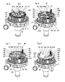
- Fig. 1 shows a spatial representation of an existing plastic material pump housing 3 with a suction nozzle 4 a discharge nozzle 5 and screw 36th
- Fig. 2 shows the pump housing 3 from Fig.1 with a mounted in a pump chamber 9 pump rotor 6, which is rotatably mounted on an axis.
- the pump rotor 6 consists essentially of a permanent magnet 8 in the form of an alternately magnetized permanent magnet ring, which is connected to a pump 7.
- Fig. 3 shows the arrangement Fig. 2 with a mounted partition 11, which separates the pump room from a drying room 10.
- the partition 11 also has screw-on 37, which correspond to the screw-on 36 of the pump housing 3.
- the partition 11 has recesses 13 for receiving stator poles, in particular its pole shoes.
- the partition wall 11 is further integrally formed with three provided with internal threads 42 mounting sockets 30 which extend parallel to a motor axis 41 of the partition wall plane.
- Fig. 4 shows the arrangement Fig. 3 with six mounted wound stator poles 14, which are aligned axially parallel and distributed uniformly around the motor axis 41.
- the stator poles 14 are each surrounded by an insulating body 15, which are provided with a stator winding 16.
- the windings are mechanically fixed to the insulating body 15 and their ends 17, 18 extend parallel to the motor shaft 41.
- First winding ends 17 terminate in a first plane while second winding ends 18 are longer than the first winding ends 17 and terminate in a second plane.
- the Isolierstoff emotions 15 are integrally with receptacles 21 a, 21 b, which extend axially parallel from the pump side facing away from peg-like.
- the further description of the stator poles 14 takes place to the FIGS. 16 to 19 ,
- Fig. 5 shows the arrangement Fig. 4 with a mounted stator yoke 20, which consists of a stack of sheets of several identically formed return plates.
- the stator yoke 20 has fastening means 29, which consist of three radial projections with disc-shaped punched holes, which coincide with the internal threads 42 of the mounting sockets 30.
- fastening means 29 consist of three radial projections with disc-shaped punched holes, which coincide with the internal threads 42 of the mounting sockets 30.
- projections 42 are provided in addition to the réellegwinden, which are dimensioned differently and prevent incorrect installation of the stator yoke 20.
- Each pole has a receiving mandrel 19, which engages in each case a correspondingly formed recess of the stator yoke 20.
- the stator yoke 20 is ring-shaped and extends within the circles described by the receptacles 21 a and 21 b.
- the stator yoke 20 is secured to the stator poles 14 by a forming operation such as caulking against loosening.
- Fig. 6 shows the arrangement Fig. 5 with a mounted contact carrier 22 which consists of plastic material.
- the contact carrier 22 is with contact receptacles 43, with mandrels 23, with openings for the receptacles 21 a and 21 b of Isolierstoff emotions, with openings for the coil ends 17, with recesses 45 in the mounting bushes 30, with a central recess 47 and with centering pin 44 a , 44b in one piece.
- the mandrels 23 are hollow and receive the second coil ends 18, which protrude clearly in the mounted state of the contact carrier from the hollow receiving mandrels 23.
- the contact receptacles are shaped so that U-shaped bent contacts can dig into it.
- a part of the U-shaped connection contacts 26 terminate on the one hand on a first side directed towards the motor axis and on the other hand in a plug plane and another part of the U-shaped connection contacts 26 end on the one hand on a second side remote from the motor axis and on the other hand in the plug plane.
- Fig. 7 shows the arrangement Figure 6 with a mounted circuit board 24, which is formed with substantially the same openings and recesses as the contact carrier 22.
- the circuit board 24 recesses 46 in the region of the mounting sockets 30, a central recess 48 and various openings for the receptacles 21 a, 21 b of Isolierstoff emotions, for the hollow receiving mandrels 23 of the contact carrier and contact breakthroughs for the electrical and mechanical connection of the first shorter coil ends 17 with the circuit board, in particular with pads, which are partially interconnected via interconnects 27.
- an opening for the contact receptacles 43 and the centering pin 44a is present.
- the receptacles 21 a and 21 a are deformed after a hot forming process so that the circuit board 24 and the contact carrier 22 are firmly connected to the six insulating bodies form-fitting, wherein the receptacles 21 a, 21 b are rivet-like deformed.
- Fig. 8 shows the arrangement Fig. 7 with a mounted heat-conducting body 25.
- the heat-conducting body 25 is made of aluminum and is provided with recesses for the hollow receiving mandrels 23, the centering pin 44a and the contact receptacles 43.
- On the spacers 31 a opposite side of the heat-conducting body further spacers 31 b are provided which serve to receive a further printed circuit board.
- the sauceleitITY consists of a first substantially disc-shaped region and a second substantially hollow cylindrical region which connects centrally to the disc-shaped region and via the central recess 48 of the circuit board 24 and the central recess 47 of the contact carrier and a central recess of the stator yoke to Partition wall 11 extends.
- Fig. 9 shows the arrangement Fig. 8 with a printed circuit board 28.
- the printed circuit board 28 has contact openings for the passage of the coil ends 18, which are electrically and mechanically connected to pads with the printed circuit board 28.
- the circuit board 28 on an opening for the contact receptacles 43.
- the printed circuit board 28 is located on the spacers 31 b axially and on the centering pins 44 a, 44 b radially and is screwed with screws 49 to the mounting sockets 30, thereby defining the heat conducting body 25 and the stator yoke in addition to the circuit board 28.
- Fig. 10 shows the arrangement Fig. 9 with mounted motor housing 50, which is integral with a connector housing 51, in which a plug 52 is inserted. Also, the motor housing is integral with Anschraubaugen 38, which coincide with the screw-on 37 of the partition 11 and the screw 36 of the pump housing.
- Fig. 11 shows a view from opposite perspective on the partition 11 with the adjoining motor housing.
- the partition wall 11 and the motor housing define the drying space, wherein the stator of the DC motor is located.
- the partition wall 11 is integral with a bearing receptacle 53 for receiving a thrust bearing for mounting the pump rotor.
- Fig. 12 shows a view from the same perspective on the stator poles 14, with the Isolierstoffön 15, the windings 16 and the hollow cylindrical portion of the bathleit stresses 25th
- Fig. 13a, 13b show views of the jacketleit stresses 25, with an opening 55a for the centering pin 44a, three openings 56a for the receiving mandrels 23 of the contact carrier, a Steckeraus Principleung 33, spacers 31 a and 31 b and a hollow cylindrical portion 54 which is centrally located on the heat conducting body.
- Fig. 13b further large recesses 57 and small recesses 58 are provided for the solder joints and rivet heads.
- Fig. 14a, 14b show views of the circuit board 24, with the interconnects 27, apertures 59a for the inner receptacles of Isolierstoff emotionss, apertures 59b for the outer receptacles of Isolierstoff emotionss, the central recess 48, the opening 55b for the centering pin 44a, apertures 56b for the receiving mandrels 23 of the contact carrier , Recesses 46 for the spacers of the sauit emotionss, a plug recess 34 and other openings for the coil ends.
- Fig. 15a, 15b show views of the contact carrier 22, with the centering pins 44a, 44b, the exception mandrels 23, the contact receptacles 43, which are integral with the contact carrier, recesses 45 for the spacers of the sauleit analysess, the central recess for receiving the cylindrical portion of the bathleit stressess, openings 60a for the inner receptacles of Isolierstoff emotions, apertures 60b for the outer receptacles of Isolierstoff emotions and breakthroughs for the winding wire ends.
- Fig. 15b are further inner centering 61 a, outer centering 61 b for mounting on the stator yoke and mating support 62, which are formed substantially conical, to add the coil ends during assembly of the contact carrier easier.
- Fig. 16 shows a representation of a stator 14, comprising a mandrel 19, for connection to the stator yoke and a pole piece 63 which has an approximately circular segment-shaped cross-sectional area.
- the stator pole 14 consists of a magnetically conductive material pressed and sintered from the powder mold.
- Fig. 17 shows the stator pole Fig. 16 with mounted insulating body 15, with a contact flange 67, a collar 35, grooves 64 in the bottom of the insulating material, which serve to achieve a regular arrangement of the winding wires to guide a wire guide 65 to the wire end after the winding process defined on the projections 66 and then to Wrap the respective fastener, one turn being sufficient.
- the insulating material further comprises receiving means 39 and 40 for receiving the stator yoke 20. To the receiving means 39 and 40 connect the inner pin-shaped receptacle 21 a and the outer pin-shaped receptacle 21 b. Both are aligned parallel to the axis.
- Fig. 18 shows the arrangement Fig. 17 wound with a winding 16. Here it is easy to see how the wire guide is occupied by the winding wire and how the winding wire end is wound around the fastening means.
- Fig. 19 shows the arrangement Fig. 18 from a different perspective.
- the pole has a polygonal cross section 12. This serves primarily to prevent rotation and finally the better use of space.
- Fig. 20a shows a second embodiment of the boss 69 and the hollow cylindrical portion 54 is closed by a bottom 70 on its side facing the pump impeller.
- This configuration results in the possibility of a large-sized capacitor 68, which is arranged on the printed circuit board 28, to accommodate space-saving in a receiving space 74 of the heat conducting body 25.
- Fig. 20b shows a third embodiment of the crableit stresses 25, in which the hollow cylindrical portion 54 is open on both sides, but in its central region, a partition wall 71 is provided, which separates the drying space from the wet space.
- the partition wall 11 (not shown here) is broken, so that an additional wet room 75 to the partition wall 71st extends.
- the third embodiment combines the first two embodiments of the heat conduction body 25 with each other.
- a space for the capacitor 68 is present, on the other hand, a part of the hollow cylindrical portion 54 can also be used as a cooling channel.
- a receiving space 73 for a bearing At the end of the hollow cylindrical portion 54 is a receiving space 73 for a bearing.
Landscapes
- Engineering & Computer Science (AREA)
- Power Engineering (AREA)
- Mechanical Engineering (AREA)
- General Engineering & Computer Science (AREA)
- Microelectronics & Electronic Packaging (AREA)
- Structures Of Non-Positive Displacement Pumps (AREA)
- Connection Of Motors, Electrical Generators, Mechanical Devices, And The Like (AREA)
Applications Claiming Priority (1)
| Application Number | Priority Date | Filing Date | Title |
|---|---|---|---|
| DE102008064159A DE102008064159B3 (de) | 2008-12-19 | 2008-12-19 | Elektronisch kommutierter Gleichstrommotor für eine Flüssigkeitspumpe |
Publications (2)
| Publication Number | Publication Date |
|---|---|
| EP2200156A2 true EP2200156A2 (fr) | 2010-06-23 |
| EP2200156A3 EP2200156A3 (fr) | 2017-03-01 |
Family
ID=41428989
Family Applications (1)
| Application Number | Title | Priority Date | Filing Date |
|---|---|---|---|
| EP09012953.7A Withdrawn EP2200156A3 (fr) | 2008-12-19 | 2009-10-14 | Moteur à courant continu commuté électroniquement pour une pompe de liquide |
Country Status (3)
| Country | Link |
|---|---|
| US (1) | US8203242B2 (fr) |
| EP (1) | EP2200156A3 (fr) |
| DE (1) | DE102008064159B3 (fr) |
Cited By (1)
| Publication number | Priority date | Publication date | Assignee | Title |
|---|---|---|---|---|
| EP2509193B1 (fr) * | 2009-11-30 | 2021-08-11 | Fujitsu General Limited | Moteur à espace axial et dispositif à pompe |
Families Citing this family (20)
| Publication number | Priority date | Publication date | Assignee | Title |
|---|---|---|---|---|
| DE202010011476U1 (de) | 2010-08-17 | 2010-11-25 | Bühler Motor GmbH | Elektronisch kommutierter Gleichstrommotor |
| DE102010034563A1 (de) | 2010-08-17 | 2012-02-23 | Bühler Motor GmbH | Elektronisch kommutierter Gleichstrommotor für eine Flüssigkeitspumpe |
| JP5260747B2 (ja) * | 2010-09-27 | 2013-08-14 | 日機装株式会社 | 耐圧防爆接続器 |
| DE102011018902A1 (de) | 2011-03-29 | 2012-10-04 | Daimler Ag | Elektromaschine, insbesondere zum Antreiben eines Kraftwagens |
| DE102011081030A1 (de) * | 2011-08-16 | 2013-02-21 | Robert Bosch Gmbh | Wicklungsträger zur Verwendung in einer elektrischen Maschine sowie Wicklungsanordnung |
| DE102012113095B4 (de) | 2011-12-29 | 2021-12-23 | Johnson Electric International AG | Bürstenloser Motor |
| DE102012200816B4 (de) * | 2012-01-20 | 2015-04-02 | Yasa Motors Poland Sp. z.o.o. | Nassläuferpumpe mit Permanentmagnet |
| DE102012200803B4 (de) * | 2012-01-20 | 2015-04-02 | Yasa Motors Poland Sp. z.o.o. | Nassläuferpumpe |
| WO2013127626A2 (fr) * | 2012-02-27 | 2013-09-06 | Ixetic Bad Homburg Gmbh | Ensemble pompe |
| GB201301305D0 (en) * | 2013-01-24 | 2013-03-06 | Gkn Evo Edrive Systems Ltd | Electrical machines |
| US9755472B2 (en) * | 2013-10-08 | 2017-09-05 | Hamilton Sundstrand Corporation | High speed rotor connection support |
| CN113202776B (zh) * | 2017-08-23 | 2023-09-15 | 浙江三花智能控制股份有限公司 | 电动泵 |
| USD928843S1 (en) * | 2019-06-20 | 2021-08-24 | Nidec Sankyo Corporation | Pump |
| KR102325215B1 (ko) * | 2020-02-26 | 2021-11-11 | 주식회사 아모텍 | 액시얼 갭 타입 전동기 및 이를 이용한 워터 펌프 |
| US12255508B2 (en) * | 2020-02-26 | 2025-03-18 | Amotech Co., Ltd. | Axial gap type motor and water pump using same |
| DE102020115642B3 (de) * | 2020-06-12 | 2021-10-07 | Gkn Sinter Metals Engineering Gmbh | Elektrischer Motor und Leiterplatte |
| EP4037158B1 (fr) | 2021-02-02 | 2025-07-30 | Black & Decker, Inc. | Moteur sans balai comprenant un pont de palier imbriqué |
| CN114709944B (zh) * | 2022-03-04 | 2026-02-03 | 浙江盘毂动力科技有限公司 | 一种轴向磁场电机及其定子 |
| EP4474650B1 (fr) | 2023-06-09 | 2026-03-25 | Illinois Tool Works Inc. | Pompe à vis et ses composants |
| US12533995B2 (en) | 2023-08-31 | 2026-01-27 | Illinois Tool Works Inc. | Battery electric vehicle temperature-regulation system |
Family Cites Families (12)
| Publication number | Priority date | Publication date | Assignee | Title |
|---|---|---|---|---|
| US4250419A (en) * | 1973-04-02 | 1981-02-10 | General Electric Company | Holder for overload protector |
| US4039875A (en) * | 1975-11-07 | 1977-08-02 | Computer Devices Corporation | Method and apparatus for interconnecting stator coils |
| US4287446A (en) * | 1979-06-27 | 1981-09-01 | Amp Incorporated | Stator for stepper motor |
| DE19646617A1 (de) * | 1996-11-12 | 1998-05-14 | Pierburg Ag | Kühlmittelpumpe mit elektrisch kommutiertem Elektromotor |
| JP2003148343A (ja) * | 2001-11-08 | 2003-05-21 | Sanden Corp | 電動圧縮機 |
| DE10253072A1 (de) * | 2002-11-07 | 2004-05-27 | Brose Fahrzeugteile Gmbh & Co. Kg, Coburg | Elektromagnetisches Bauteil |
| WO2004088818A1 (fr) * | 2003-03-31 | 2004-10-14 | Matsushita Electric Industrial Co., Ltd. | Moteur avec mise a la masse hautement fiable et dispositif electrique equipe dudit moteur |
| CA2533252C (fr) * | 2003-07-24 | 2014-11-04 | Tesma International Inc. | Pompe a fluide electrique |
| US6975052B2 (en) * | 2003-08-29 | 2005-12-13 | Japan Servo Co., Ltd. | Terminal arrangement of motor and capacitor motor |
| DE202004010956U1 (de) * | 2004-07-13 | 2005-11-24 | Minebea Co., Ltd., Kitasaku | Einrichtung zur Isolation von Statornuten |
| JP2007014147A (ja) * | 2005-06-30 | 2007-01-18 | Fujitsu General Ltd | 電動機 |
| JP2007129847A (ja) * | 2005-11-04 | 2007-05-24 | Denso Corp | 電動機およびそれを用いた燃料ポンプ |
-
2008
- 2008-12-19 DE DE102008064159A patent/DE102008064159B3/de active Active
-
2009
- 2009-10-14 EP EP09012953.7A patent/EP2200156A3/fr not_active Withdrawn
- 2009-12-15 US US12/654,240 patent/US8203242B2/en active Active
Non-Patent Citations (1)
| Title |
|---|
| None * |
Cited By (1)
| Publication number | Priority date | Publication date | Assignee | Title |
|---|---|---|---|---|
| EP2509193B1 (fr) * | 2009-11-30 | 2021-08-11 | Fujitsu General Limited | Moteur à espace axial et dispositif à pompe |
Also Published As
| Publication number | Publication date |
|---|---|
| US8203242B2 (en) | 2012-06-19 |
| DE102008064159B3 (de) | 2010-01-28 |
| EP2200156A3 (fr) | 2017-03-01 |
| US20100158724A1 (en) | 2010-06-24 |
Similar Documents
| Publication | Publication Date | Title |
|---|---|---|
| DE102008064159B3 (de) | Elektronisch kommutierter Gleichstrommotor für eine Flüssigkeitspumpe | |
| DE102008064161B4 (de) | Elektronisch kommutierter Gleichstrommotor für eine Flüssigkeitspumpe | |
| EP2199617B1 (fr) | Pompe centrifuge avec arbre fixe | |
| EP2302219B1 (fr) | Unité de pompage | |
| EP3078099B1 (fr) | Stator pour moteur à courant continu à commutation électronique | |
| EP1947343B1 (fr) | Unité de pompage | |
| DE60216863T2 (de) | Elektrischer Motor mit zwei Rotoren und einem Stator | |
| DE19705974A1 (de) | Elektromotor für eine Pumpe oder einen Lüfter | |
| DE102008012680A1 (de) | Elektrische Maschine | |
| EP0963029A2 (fr) | Pompe à tube d'entrefer avec support d'enroulement | |
| DE10115852A1 (de) | Elektrische Umlaufvorrichtung sowie zugehöriges Herstellungsverfahren | |
| DE102008053233A1 (de) | Kraftstoffpumpe | |
| WO2013174523A2 (fr) | Système de stator pour moteur électrique | |
| EP3155710B1 (fr) | Stator d'une machine électrique | |
| EP1648074B1 (fr) | Machine électrique, en particulier moteur à courant continu | |
| DE102014201490A1 (de) | Kreiselpumpenmotor | |
| DE102008064131A1 (de) | Elektrische Maschine | |
| WO2016062813A1 (fr) | Dispositif stator pour un moteur électrique et utilisation dudit dispositif | |
| EP3646443A1 (fr) | Dispositif de câblage d'un stator pour machine électrique rotative | |
| WO2020083559A1 (fr) | Pompe comprenant un moteur électrique ayant un unité de barres collectrices compact | |
| EP3391509B1 (fr) | Moteur électrique | |
| DE102005001697B4 (de) | Elektrischer Motor und Fluidpumpe, die diesen verwendet | |
| DE102018221859B4 (de) | Kommutatormotor und Baureihe von Kommutatormotoren | |
| DE102019104706A1 (de) | Elektrische Kontaktierung von Statoranschlüssen auf einer Leiterplatte mittels horizontal ausgerichteten Schneidklemmkontakten | |
| DE202010011476U1 (de) | Elektronisch kommutierter Gleichstrommotor |
Legal Events
| Date | Code | Title | Description |
|---|---|---|---|
| PUAI | Public reference made under article 153(3) epc to a published international application that has entered the european phase |
Free format text: ORIGINAL CODE: 0009012 |
|
| AK | Designated contracting states |
Kind code of ref document: A2 Designated state(s): AT BE BG CH CY CZ DE DK EE ES FI FR GB GR HR HU IE IS IT LI LT LU LV MC MK MT NL NO PL PT RO SE SI SK SM TR |
|
| AX | Request for extension of the european patent |
Extension state: AL BA RS |
|
| PUAL | Search report despatched |
Free format text: ORIGINAL CODE: 0009013 |
|
| AK | Designated contracting states |
Kind code of ref document: A3 Designated state(s): AT BE BG CH CY CZ DE DK EE ES FI FR GB GR HR HU IE IS IT LI LT LU LV MC MK MT NL NO PL PT RO SE SI SK SM TR |
|
| AX | Request for extension of the european patent |
Extension state: AL BA RS |
|
| RIC1 | Information provided on ipc code assigned before grant |
Ipc: H02K 3/52 20060101AFI20170123BHEP Ipc: F04D 13/06 20060101ALI20170123BHEP Ipc: H02K 11/00 20160101ALI20170123BHEP Ipc: H02K 1/14 20060101ALI20170123BHEP |
|
| 17P | Request for examination filed |
Effective date: 20170306 |
|
| 17Q | First examination report despatched |
Effective date: 20170710 |
|
| GRAP | Despatch of communication of intention to grant a patent |
Free format text: ORIGINAL CODE: EPIDOSNIGR1 |
|
| INTG | Intention to grant announced |
Effective date: 20170811 |
|
| RIN1 | Information on inventor provided before grant (corrected) |
Inventor name: IHLE, OLAI Inventor name: WEISKE, KLAUS Inventor name: BERNREUTHER, GEORG |
|
| STAA | Information on the status of an ep patent application or granted ep patent |
Free format text: STATUS: THE APPLICATION IS DEEMED TO BE WITHDRAWN |
|
| 18D | Application deemed to be withdrawn |
Effective date: 20171222 |