EP2509193B1 - Moteur à espace axial et dispositif à pompe - Google Patents
Moteur à espace axial et dispositif à pompe Download PDFInfo
- Publication number
- EP2509193B1 EP2509193B1 EP10832927.7A EP10832927A EP2509193B1 EP 2509193 B1 EP2509193 B1 EP 2509193B1 EP 10832927 A EP10832927 A EP 10832927A EP 2509193 B1 EP2509193 B1 EP 2509193B1
- Authority
- EP
- European Patent Office
- Prior art keywords
- axis line
- stator
- contact surfaces
- rotor
- axial gap
- Prior art date
- Legal status (The legal status is an assumption and is not a legal conclusion. Google has not performed a legal analysis and makes no representation as to the accuracy of the status listed.)
- Active
Links
Images






Classifications
-
- F—MECHANICAL ENGINEERING; LIGHTING; HEATING; WEAPONS; BLASTING
- F04—POSITIVE - DISPLACEMENT MACHINES FOR LIQUIDS; PUMPS FOR LIQUIDS OR ELASTIC FLUIDS
- F04D—NON-POSITIVE-DISPLACEMENT PUMPS
- F04D13/00—Pumping installations or systems
- F04D13/02—Units comprising pumps and their driving means
- F04D13/06—Units comprising pumps and their driving means the pump being electrically driven
- F04D13/0606—Canned motor pumps
- F04D13/064—Details of the magnetic circuit
-
- F—MECHANICAL ENGINEERING; LIGHTING; HEATING; WEAPONS; BLASTING
- F04—POSITIVE - DISPLACEMENT MACHINES FOR LIQUIDS; PUMPS FOR LIQUIDS OR ELASTIC FLUIDS
- F04D—NON-POSITIVE-DISPLACEMENT PUMPS
- F04D13/00—Pumping installations or systems
- F04D13/02—Units comprising pumps and their driving means
- F04D13/06—Units comprising pumps and their driving means the pump being electrically driven
- F04D13/0606—Canned motor pumps
- F04D13/0626—Details of the can
-
- F—MECHANICAL ENGINEERING; LIGHTING; HEATING; WEAPONS; BLASTING
- F04—POSITIVE - DISPLACEMENT MACHINES FOR LIQUIDS; PUMPS FOR LIQUIDS OR ELASTIC FLUIDS
- F04D—NON-POSITIVE-DISPLACEMENT PUMPS
- F04D13/00—Pumping installations or systems
- F04D13/02—Units comprising pumps and their driving means
- F04D13/06—Units comprising pumps and their driving means the pump being electrically driven
- F04D13/0666—Units comprising pumps and their driving means the pump being electrically driven the motor being of the plane gap type
-
- H—ELECTRICITY
- H02—GENERATION; CONVERSION OR DISTRIBUTION OF ELECTRIC POWER
- H02K—DYNAMO-ELECTRIC MACHINES
- H02K1/00—Details of the magnetic circuit
- H02K1/06—Details of the magnetic circuit characterised by the shape, form or construction
- H02K1/12—Stationary parts of the magnetic circuit
- H02K1/14—Stator cores with salient poles
- H02K1/146—Stator cores with salient poles consisting of a generally annular yoke with salient poles
- H02K1/148—Sectional cores
Definitions
- US2007/001540A1 describes an axial air-gap electronic motor in which a stator is formed by a plurality of core members.
- a hook portion which is a first connecting means, is projectingly provided at one end in the circumferential direction of a flange portion of each of the core members, and a columnar locking shaft to which the hook portion is locked is provided at the other end in the circumferential direction of the flange portion, by which the core members are connected to each other.
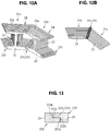
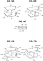
- the stator iron core 24 includes a winding section 22 around which a not-shown winding wire is wound via the insulator 40 and the yoke strip 23 integrally formed on the proximal end side of the winding section 22.
- a fan-shaped teeth surface 22a opposed to the rotor magnet 31 of the rotor 3 is integrally provided on the distal end side (in Figure 1 , the right lateral surface side) of the winding section 22, a fan-shaped teeth surface 22a opposed to the rotor magnet 31 of the rotor 3 is integrally provided.
- the stator iron core 24 is formed in a bobbin shape including the flange-like teeth surface 22a and the yoke strip 23 at both ends of the winding section 22.
- Terminal holes into which the terminal pins are inserted are drilled at the distal ends of the terminal blocks 47, 47.
- the terminal blocks 47, 47 are not provided in the flange section 41 on the teeth surface 22a side.
Landscapes
- Engineering & Computer Science (AREA)
- Mechanical Engineering (AREA)
- General Engineering & Computer Science (AREA)
- Power Engineering (AREA)
- Iron Core Of Rotating Electric Machines (AREA)
- Structures Of Non-Positive Displacement Pumps (AREA)
Claims (7)
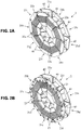
- Moteur à espace axial (1), qui est destiné à être utilisé dans un dispositif à pompe (P) , dans lequel un stator (2) et un rotor (3) sont disposés pour être opposés l'un à l'autre avec un espace prédéfini le long d'une direction de ligne d'axe d'un arbre de sortie de rotor (4) du rotor, une paroi de séparation étanche (Pw) interposée entre le stator et le rotor, le stator comprenant plusieurs éléments noyaux (20a, 20b,... , 20i) disposés de manière annulaire en se centrant sur une ligne d'axe de l'arbre de sortie du rotor, et les éléments noyaux étant accouplés les uns aux autres par l'intermédiaire d'un moyen d'accouplement prédéfini,
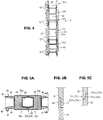
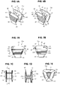
chacun des éléments noyaux comprenant un noyau de fer de stator (24) comprenant une surface de dents (22a) opposée au rotor, une section d'enroulement (22) qui s'étend dans la direction de ligne d'axe depuis la surface de dents et autour de laquelle un fil d'enroulement est enroulé, et une bande de culasse (23) pour accoupler les éléments noyaux afin de former une partie d'une section de culasse annulaire sur un côté d'extrémité dans la direction de ligne d'axe du stator, des surfaces de contact (231, 232) des éléments noyaux adjacents les uns aux autres dans la direction circonférentielle qui viennent en contact avec la bande de culasse étant situées sur les deux côtés d'extrémité dans la direction circonférentielle de la bande de culasse, et, lorsque l'aire de surface des surfaces de contact est représentée par As, l'aire projetée de la surface latérale de la bande de culasse vue depuis la direction circonférentielle est représentée par Ap, les surfaces de contact et les surfaces latérales étant formées pour satisfaire une relation As>Ap,
l'élément noyau comprenant en outre un isolant (40) qui couvre une circonférence extérieure du noyau de fer de stator en laissant la surface des dents de la section d'enroulement, l'isolant étant formé en forme de bobine comprenant une paire de sections de bride parallèles l'une à l'autre le long de la surface des dents et de la bande de culasse, et une bride supérieure (41) sur le côté de surface des dents étant formée pour être plus basse que la surface des dents dans la direction de ligne d'axe, et
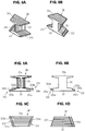
une section de crochet (43) fonctionnant comme premier moyen d'accouplement étant disposée en saillie sur un côté d'extrémité dans la direction circonférentielle de la section de bride, un arbre de verrouillage (44) auquel la section de crochet est verrouillée étant situé sur l'autre côté d'extrémité dans la direction circonférentielle de la section de bride, et l'arbre de verrouillage étant formé pour avoir une hauteur de direction axiale inférieure à la surface des dents dans la direction de ligne d'axe de sorte que la surface des dents soit la surface la plus extérieure de l'élément noyau dans la direction de ligne d'axe. - Moteur à espace axial selon la revendication 1, caractérisé en ce que chacune des surfaces de contact comprend deux surfaces ou plus, et au moins l'une des surfaces (231c, 232c) est disposée sensiblement parallèle à la surface des dents.
- Moteur à espace axial selon la revendication 1 ou 2, caractérisé en ce que chacune des surfaces de contact comprend une surface arquée, et la surface arquée est formée en une forme convexe ou concave dans la direction circonférentielle.
- Moteur à espace axial selon la revendication 1, 2 ou 3, caractérisé en ce qu'un moyen de prévention de déviation de position (233, 234) est disposé sur chacune des surfaces de contact pour empêcher une déviation de position dans un état dans lequel les surfaces de contact sont alignées les unes avec les autres.
- Moteur à espace axial selon la revendication 1, caractérisé en ce que, lorsque les éléments noyaux sont accouplés les uns aux autres, des parties des sections de bride adjacentes les unes aux autres sont disposées pour se chevaucher les unes les autres dans la direction de ligne d'axe et une section de contact (43, 441) sur le côté de bande de culasse où les sections de bride se chevauchent les unes les autres et les surfaces de contact des éléments noyaux sont disposées de sorte que les directions de chevauchement sont alternées dans la direction de ligne d'axe.
- Moteur à espace axial selon la revendication 1 ou 2, caractérisé en ce que l'élément noyau comprend une plaque d'acier laminé, et les surfaces de contact sont disposées pour être sensiblement parallèles à une direction de laminage de la plaque d'acier laminé et perpendiculaires à la direction de ligne d'axe.
- Dispositif à pompe (P) utilisant le moteur à espace axial selon l'une quelconque des revendications 1 à 6, caractérisé en ce que le dispositif à pompe est divisé en une chambre de moteur (Mc) et une chambre de pompe (Pc) par la paroi de séparation (Pw) dans laquelle sont situées une partie épaisse (52) ayant une grande épaisseur et une partie mince (51) ayant une petite épaisseur dans la direction de ligne d'axe, dans la chambre de moteur, le stator du moteur à espace axial étant disposé de sorte que la surface des dents soit opposée à la partie mince de la paroi de séparation, et, dans la chambre de pompe, le rotor du moteur à espace axial étant disposé pour être opposé au stator à travers la paroi de séparation.
Applications Claiming Priority (2)
| Application Number | Priority Date | Filing Date | Title |
|---|---|---|---|
| JP2009271062A JP4716060B2 (ja) | 2009-11-30 | 2009-11-30 | アキシャルギャップ型電動機およびポンプ装置 |
| PCT/JP2010/064860 WO2011065080A1 (fr) | 2009-11-30 | 2010-09-01 | Moteur à espace axial et dispositif à pompe |
Publications (3)
| Publication Number | Publication Date |
|---|---|
| EP2509193A1 EP2509193A1 (fr) | 2012-10-10 |
| EP2509193A4 EP2509193A4 (fr) | 2016-09-28 |
| EP2509193B1 true EP2509193B1 (fr) | 2021-08-11 |
Family
ID=44066183
Family Applications (1)
| Application Number | Title | Priority Date | Filing Date |
|---|---|---|---|
| EP10832927.7A Active EP2509193B1 (fr) | 2009-11-30 | 2010-09-01 | Moteur à espace axial et dispositif à pompe |
Country Status (5)
| Country | Link |
|---|---|
| US (1) | US8917007B2 (fr) |
| EP (1) | EP2509193B1 (fr) |
| JP (1) | JP4716060B2 (fr) |
| CN (1) | CN102656772B (fr) |
| WO (1) | WO2011065080A1 (fr) |
Families Citing this family (26)
| Publication number | Priority date | Publication date | Assignee | Title |
|---|---|---|---|---|
| KR101321286B1 (ko) * | 2012-02-23 | 2013-10-28 | 삼성전기주식회사 | 다상 스위치드 릴럭턴스 모터 장치 |
| WO2014011783A1 (fr) * | 2012-07-11 | 2014-01-16 | Remy Technologies, Llc | Isolateurs de bobinages interbloquants pour rétention de résine dans un ensemble stator segmenté |
| KR101405225B1 (ko) | 2012-12-12 | 2014-06-10 | 현대자동차 주식회사 | 보빈 및 그를 이용한 권선형 동기모터의 회전자 |
| KR101426170B1 (ko) | 2012-12-28 | 2014-08-07 | 주식회사 효성 | 슬롯 레스용 전동기 고정자 |
| GB201301305D0 (en) * | 2013-01-24 | 2013-03-06 | Gkn Evo Edrive Systems Ltd | Electrical machines |
| DE102014203945A1 (de) * | 2014-03-05 | 2015-09-10 | Robert Bosch Gmbh | Statorelement zum Aufbau einer Statoranordnung für eine elektrische Maschine, Statoranordnung und Verfahren zum Aufbau einer Statoranordnung |
| CN105406674A (zh) * | 2015-12-10 | 2016-03-16 | 皖西学院 | 一种能够降低振动噪声的开关磁阻电机结构 |
| FR3046888B1 (fr) * | 2016-01-14 | 2021-10-22 | Whylot | Stator pour machine electromagnetique a flux axial avec des portions unitaires formant une couronne du stator |
| CN109565192A (zh) * | 2016-09-02 | 2019-04-02 | 日本电产株式会社 | 定子、定子的制造方法及马达 |
| WO2018043650A1 (fr) * | 2016-09-02 | 2018-03-08 | 日本電産株式会社 | Stator, procédé de fabrication d'un stator, et moteur |
| FR3061370B1 (fr) * | 2016-12-27 | 2022-05-13 | Francecol Tech | Ensemble electromagnetique a structure polyphasee |
| FR3064423B1 (fr) * | 2017-03-22 | 2019-11-15 | Whylot Sas | Rotor pour moteur ou generatrice electromagnetique a structure alveolaire comportant des alveoles pour le logement d'aimants respectifs |
| KR102452689B1 (ko) * | 2017-09-26 | 2022-10-11 | 현대자동차주식회사 | 오일 코일순환방식 모터 및 친환경차량 |
| US10256688B1 (en) * | 2017-10-10 | 2019-04-09 | Zero E Technologies, Llc | Electric machine rotor cooling systems and methods |
| KR102529494B1 (ko) * | 2017-12-20 | 2023-05-04 | 현대자동차주식회사 | 레졸버 |
| EP3648306A1 (fr) * | 2018-10-30 | 2020-05-06 | Siemens Gamesa Renewable Energy A/S | Machine électrique comportant un stator ou un rotor segmenté |
| WO2020116038A1 (fr) * | 2018-12-05 | 2020-06-11 | 住友電気工業株式会社 | Noyau, stator et machine électrique rotative |
| JP7395870B2 (ja) * | 2019-08-09 | 2023-12-12 | セイコーエプソン株式会社 | アキシャルギャップモーター |
| JP2021048751A (ja) | 2019-09-20 | 2021-03-25 | セイコーエプソン株式会社 | アキシャルギャップモーター |
| KR102511276B1 (ko) * | 2020-10-12 | 2023-03-20 | 한국생산기술연구원 | 축방향 자속형 모터용 평각형 코일 및 코어 |
| CN112350461A (zh) * | 2020-10-21 | 2021-02-09 | 北京自动化控制设备研究所 | 一种高机械强度模块化轴向磁通电机 |
| US11677303B2 (en) * | 2021-10-21 | 2023-06-13 | National Cheng Kung University | Motor and coreless stator coil winding unit thereof |
| KR20230086165A (ko) * | 2021-12-08 | 2023-06-15 | 현대자동차주식회사 | 전동식 워터 펌프 |
| DE102021215040A1 (de) | 2021-12-27 | 2023-06-29 | Robert Bosch Gesellschaft mit beschränkter Haftung | Stator, Axialflussmaschine und Pumpe |
| DE102021215043A1 (de) | 2021-12-27 | 2023-06-29 | Robert Bosch Gesellschaft mit beschränkter Haftung | Axialflussmaschine und Pumpe |
| KR20260008497A (ko) * | 2024-07-09 | 2026-01-16 | 주식회사 아모텍 | 액시얼 갭 타입 전동기를 이용한 워터 펌프 |
Citations (1)
| Publication number | Priority date | Publication date | Assignee | Title |
|---|---|---|---|---|
| EP2200156A2 (fr) * | 2008-12-19 | 2010-06-23 | Bühler Motor GmbH | Moteur à courant continu commuté électroniquement pour une pompe de liquide |
Family Cites Families (17)
| Publication number | Priority date | Publication date | Assignee | Title |
|---|---|---|---|---|
| CA1004274A (en) * | 1974-04-04 | 1977-01-25 | Canadian General Electric Company Limited | Permanent magnet hermetic synchronous motor |
| JPS5532696U (fr) * | 1978-08-25 | 1980-03-03 | ||
| JPH09209969A (ja) * | 1996-01-29 | 1997-08-12 | Shibaura Eng Works Co Ltd | ポンプ |
| GB2310545B (en) * | 1996-02-22 | 2000-04-19 | Honda Motor Co Ltd | Stator core and method and apparatus for assembling same |
| JP3306645B2 (ja) * | 1996-02-22 | 2002-07-24 | 本田技研工業株式会社 | ステータコア |
| JP2001119872A (ja) * | 1999-10-15 | 2001-04-27 | Mitsubishi Electric Corp | 同期回転電機及び風力発電機並びにその製造方法 |
| TW508891B (en) * | 2000-02-21 | 2002-11-01 | Misubishi Electric Corp | Stator iron core of electric motor, manufacturing method thereof, electric motor, and compresor |
| FR2851088B1 (fr) * | 2003-02-12 | 2006-01-27 | Seb Sa | Stator pour moteur electrique a flux axial |
| JP4305649B2 (ja) * | 2003-02-26 | 2009-07-29 | 株式会社富士通ゼネラル | アキシャルギャップ型電動機 |
| JP2006050745A (ja) * | 2004-08-03 | 2006-02-16 | Nissan Motor Co Ltd | アキシャルギャップ回転電機 |
| JP2007014147A (ja) * | 2005-06-30 | 2007-01-18 | Fujitsu General Ltd | 電動機 |
| JP4816879B2 (ja) * | 2005-06-30 | 2011-11-16 | 株式会社富士通ゼネラル | アキシャルエアギャップ型電動機 |
| JP2007110808A (ja) * | 2005-10-12 | 2007-04-26 | Toyota Motor Corp | モーター用コア |
| JP4611905B2 (ja) * | 2006-01-31 | 2011-01-12 | 三菱電機株式会社 | 電動機の固定子 |
| JP4868147B2 (ja) | 2006-11-08 | 2012-02-01 | 株式会社富士通ゼネラル | アキシャルエアギャップ型電動機 |
| JP5171224B2 (ja) * | 2007-11-22 | 2013-03-27 | 三菱電機株式会社 | 回転電機 |
| JP2010220288A (ja) | 2009-03-13 | 2010-09-30 | Mabuchi Motor Co Ltd | コアブロック及び該コアブロックを用いたモータ用の磁極コア |
-
2009
- 2009-11-30 JP JP2009271062A patent/JP4716060B2/ja not_active Expired - Fee Related
-
2010
- 2010-09-01 EP EP10832927.7A patent/EP2509193B1/fr active Active
- 2010-09-01 CN CN201080054211.3A patent/CN102656772B/zh active Active
- 2010-09-01 WO PCT/JP2010/064860 patent/WO2011065080A1/fr not_active Ceased
- 2010-09-01 US US13/512,505 patent/US8917007B2/en active Active
Patent Citations (1)
| Publication number | Priority date | Publication date | Assignee | Title |
|---|---|---|---|---|
| EP2200156A2 (fr) * | 2008-12-19 | 2010-06-23 | Bühler Motor GmbH | Moteur à courant continu commuté électroniquement pour une pompe de liquide |
Also Published As
| Publication number | Publication date |
|---|---|
| EP2509193A1 (fr) | 2012-10-10 |
| US8917007B2 (en) | 2014-12-23 |
| CN102656772A (zh) | 2012-09-05 |
| US20120263612A1 (en) | 2012-10-18 |
| WO2011065080A1 (fr) | 2011-06-03 |
| EP2509193A4 (fr) | 2016-09-28 |
| JP4716060B2 (ja) | 2011-07-06 |
| JP2011114993A (ja) | 2011-06-09 |
| CN102656772B (zh) | 2015-03-18 |
Similar Documents
| Publication | Publication Date | Title |
|---|---|---|
| EP2509193A1 (fr) | Moteur à espace axial et dispositif à pompe | |
| US10574098B2 (en) | Stator, motor comprising the same and method for making the same | |
| US7323801B2 (en) | Axial air-gap electronic motor | |
| EP3176912B1 (fr) | Stator et machine tournante | |
| CN101494399B (zh) | 马达及具备该马达的马达一体型泵 | |
| US10340753B2 (en) | Stator of planar type motor, and planar type motor using same | |
| US20210203200A1 (en) | Rotor for electric motor and brushless motor | |
| US20150008769A1 (en) | Motor and method of manufacturing motor | |
| US7667368B2 (en) | Axial air-gap electronic motor | |
| US9455602B2 (en) | Motor | |
| US9923421B2 (en) | Rotor structure for motor | |
| JP2011019360A (ja) | ステータおよびステータの製造方法 | |
| JPWO2013121590A1 (ja) | 回転電機 | |
| KR20170055003A (ko) | 고정자 및 이를 갖는 bldc 모터 | |
| TWI673936B (zh) | 軸向間隙型旋轉電機 | |
| US8823240B2 (en) | Stator and rotating electrical machine | |
| WO2014119239A1 (fr) | Rotor et moteur | |
| CN106300711B (zh) | 用于电机的定子、电机、车辆和制造方法 | |
| JP2012016216A (ja) | 回転電機 | |
| EP3945658A1 (fr) | Moteur polyphasé, procédé de fabrication et appareil de cuisine | |
| US20200099262A1 (en) | Polyphase claw pole motor | |
| CN113812063B (zh) | 同步电动机 | |
| JP2010088166A (ja) | アキシャルエアギャップ型電動機 | |
| JP2018519778A (ja) | 磁束損失を制限するローターを有する回転電気機械、特に電気モーター | |
| KR101597967B1 (ko) | 평판형 모터의 고정자 및 이를 이용한 평판형 모터 |
Legal Events
| Date | Code | Title | Description |
|---|---|---|---|
| PUAI | Public reference made under article 153(3) epc to a published international application that has entered the european phase |
Free format text: ORIGINAL CODE: 0009012 |
|
| 17P | Request for examination filed |
Effective date: 20120521 |
|
| AK | Designated contracting states |
Kind code of ref document: A1 Designated state(s): AL AT BE BG CH CY CZ DE DK EE ES FI FR GB GR HR HU IE IS IT LI LT LU LV MC MK MT NL NO PL PT RO SE SI SK SM TR |
|
| DAX | Request for extension of the european patent (deleted) | ||
| RA4 | Supplementary search report drawn up and despatched (corrected) |
Effective date: 20160825 |
|
| RIC1 | Information provided on ipc code assigned before grant |
Ipc: H02K 1/18 20060101AFI20160819BHEP Ipc: H02K 1/14 20060101ALI20160819BHEP Ipc: F04D 13/06 20060101ALI20160819BHEP |
|
| STAA | Information on the status of an ep patent application or granted ep patent |
Free format text: STATUS: EXAMINATION IS IN PROGRESS |
|
| 17Q | First examination report despatched |
Effective date: 20170929 |
|
| GRAP | Despatch of communication of intention to grant a patent |
Free format text: ORIGINAL CODE: EPIDOSNIGR1 |
|
| STAA | Information on the status of an ep patent application or granted ep patent |
Free format text: STATUS: GRANT OF PATENT IS INTENDED |
|
| INTG | Intention to grant announced |
Effective date: 20210224 |
|
| GRAS | Grant fee paid |
Free format text: ORIGINAL CODE: EPIDOSNIGR3 |
|
| GRAA | (expected) grant |
Free format text: ORIGINAL CODE: 0009210 |
|
| STAA | Information on the status of an ep patent application or granted ep patent |
Free format text: STATUS: THE PATENT HAS BEEN GRANTED |
|
| AK | Designated contracting states |
Kind code of ref document: B1 Designated state(s): AL AT BE BG CH CY CZ DE DK EE ES FI FR GB GR HR HU IE IS IT LI LT LU LV MC MK MT NL NO PL PT RO SE SI SK SM TR |
|
| REG | Reference to a national code |
Ref country code: GB Ref legal event code: FG4D |
|
| REG | Reference to a national code |
Ref country code: CH Ref legal event code: EP |
|
| REG | Reference to a national code |
Ref country code: DE Ref legal event code: R096 Ref document number: 602010067422 Country of ref document: DE |
|
| REG | Reference to a national code |
Ref country code: IE Ref legal event code: FG4D Ref country code: AT Ref legal event code: REF Ref document number: 1420394 Country of ref document: AT Kind code of ref document: T Effective date: 20210915 |
|
| REG | Reference to a national code |
Ref country code: LT Ref legal event code: MG9D |
|
| REG | Reference to a national code |
Ref country code: NL Ref legal event code: MP Effective date: 20210811 |
|
| REG | Reference to a national code |
Ref country code: AT Ref legal event code: MK05 Ref document number: 1420394 Country of ref document: AT Kind code of ref document: T Effective date: 20210811 |
|
| PG25 | Lapsed in a contracting state [announced via postgrant information from national office to epo] |
Ref country code: HR Free format text: LAPSE BECAUSE OF FAILURE TO SUBMIT A TRANSLATION OF THE DESCRIPTION OR TO PAY THE FEE WITHIN THE PRESCRIBED TIME-LIMIT Effective date: 20210811 Ref country code: SE Free format text: LAPSE BECAUSE OF FAILURE TO SUBMIT A TRANSLATION OF THE DESCRIPTION OR TO PAY THE FEE WITHIN THE PRESCRIBED TIME-LIMIT Effective date: 20210811 Ref country code: AT Free format text: LAPSE BECAUSE OF FAILURE TO SUBMIT A TRANSLATION OF THE DESCRIPTION OR TO PAY THE FEE WITHIN THE PRESCRIBED TIME-LIMIT Effective date: 20210811 Ref country code: BG Free format text: LAPSE BECAUSE OF FAILURE TO SUBMIT A TRANSLATION OF THE DESCRIPTION OR TO PAY THE FEE WITHIN THE PRESCRIBED TIME-LIMIT Effective date: 20211111 Ref country code: LT Free format text: LAPSE BECAUSE OF FAILURE TO SUBMIT A TRANSLATION OF THE DESCRIPTION OR TO PAY THE FEE WITHIN THE PRESCRIBED TIME-LIMIT Effective date: 20210811 Ref country code: PT Free format text: LAPSE BECAUSE OF FAILURE TO SUBMIT A TRANSLATION OF THE DESCRIPTION OR TO PAY THE FEE WITHIN THE PRESCRIBED TIME-LIMIT Effective date: 20211213 Ref country code: NO Free format text: LAPSE BECAUSE OF FAILURE TO SUBMIT A TRANSLATION OF THE DESCRIPTION OR TO PAY THE FEE WITHIN THE PRESCRIBED TIME-LIMIT Effective date: 20211111 Ref country code: ES Free format text: LAPSE BECAUSE OF FAILURE TO SUBMIT A TRANSLATION OF THE DESCRIPTION OR TO PAY THE FEE WITHIN THE PRESCRIBED TIME-LIMIT Effective date: 20210811 Ref country code: FI Free format text: LAPSE BECAUSE OF FAILURE TO SUBMIT A TRANSLATION OF THE DESCRIPTION OR TO PAY THE FEE WITHIN THE PRESCRIBED TIME-LIMIT Effective date: 20210811 |
|
| PG25 | Lapsed in a contracting state [announced via postgrant information from national office to epo] |
Ref country code: PL Free format text: LAPSE BECAUSE OF FAILURE TO SUBMIT A TRANSLATION OF THE DESCRIPTION OR TO PAY THE FEE WITHIN THE PRESCRIBED TIME-LIMIT Effective date: 20210811 Ref country code: LV Free format text: LAPSE BECAUSE OF FAILURE TO SUBMIT A TRANSLATION OF THE DESCRIPTION OR TO PAY THE FEE WITHIN THE PRESCRIBED TIME-LIMIT Effective date: 20210811 Ref country code: GR Free format text: LAPSE BECAUSE OF FAILURE TO SUBMIT A TRANSLATION OF THE DESCRIPTION OR TO PAY THE FEE WITHIN THE PRESCRIBED TIME-LIMIT Effective date: 20211112 |
|
| PG25 | Lapsed in a contracting state [announced via postgrant information from national office to epo] |
Ref country code: NL Free format text: LAPSE BECAUSE OF FAILURE TO SUBMIT A TRANSLATION OF THE DESCRIPTION OR TO PAY THE FEE WITHIN THE PRESCRIBED TIME-LIMIT Effective date: 20210811 |
|
| PG25 | Lapsed in a contracting state [announced via postgrant information from national office to epo] |
Ref country code: DK Free format text: LAPSE BECAUSE OF FAILURE TO SUBMIT A TRANSLATION OF THE DESCRIPTION OR TO PAY THE FEE WITHIN THE PRESCRIBED TIME-LIMIT Effective date: 20210811 |
|
| REG | Reference to a national code |
Ref country code: DE Ref legal event code: R097 Ref document number: 602010067422 Country of ref document: DE |
|
| REG | Reference to a national code |
Ref country code: CH Ref legal event code: PL |
|
| REG | Reference to a national code |
Ref country code: BE Ref legal event code: MM Effective date: 20210930 |
|
| PG25 | Lapsed in a contracting state [announced via postgrant information from national office to epo] |
Ref country code: SM Free format text: LAPSE BECAUSE OF FAILURE TO SUBMIT A TRANSLATION OF THE DESCRIPTION OR TO PAY THE FEE WITHIN THE PRESCRIBED TIME-LIMIT Effective date: 20210811 Ref country code: SK Free format text: LAPSE BECAUSE OF FAILURE TO SUBMIT A TRANSLATION OF THE DESCRIPTION OR TO PAY THE FEE WITHIN THE PRESCRIBED TIME-LIMIT Effective date: 20210811 Ref country code: RO Free format text: LAPSE BECAUSE OF FAILURE TO SUBMIT A TRANSLATION OF THE DESCRIPTION OR TO PAY THE FEE WITHIN THE PRESCRIBED TIME-LIMIT Effective date: 20210811 Ref country code: MC Free format text: LAPSE BECAUSE OF FAILURE TO SUBMIT A TRANSLATION OF THE DESCRIPTION OR TO PAY THE FEE WITHIN THE PRESCRIBED TIME-LIMIT Effective date: 20210811 Ref country code: EE Free format text: LAPSE BECAUSE OF FAILURE TO SUBMIT A TRANSLATION OF THE DESCRIPTION OR TO PAY THE FEE WITHIN THE PRESCRIBED TIME-LIMIT Effective date: 20210811 Ref country code: CZ Free format text: LAPSE BECAUSE OF FAILURE TO SUBMIT A TRANSLATION OF THE DESCRIPTION OR TO PAY THE FEE WITHIN THE PRESCRIBED TIME-LIMIT Effective date: 20210811 Ref country code: AL Free format text: LAPSE BECAUSE OF FAILURE TO SUBMIT A TRANSLATION OF THE DESCRIPTION OR TO PAY THE FEE WITHIN THE PRESCRIBED TIME-LIMIT Effective date: 20210811 |
|
| PLBE | No opposition filed within time limit |
Free format text: ORIGINAL CODE: 0009261 |
|
| STAA | Information on the status of an ep patent application or granted ep patent |
Free format text: STATUS: NO OPPOSITION FILED WITHIN TIME LIMIT |
|
| 26N | No opposition filed |
Effective date: 20220512 |
|
| GBPC | Gb: european patent ceased through non-payment of renewal fee |
Effective date: 20211111 |
|
| PG25 | Lapsed in a contracting state [announced via postgrant information from national office to epo] |
Ref country code: LU Free format text: LAPSE BECAUSE OF NON-PAYMENT OF DUE FEES Effective date: 20210901 Ref country code: IT Free format text: LAPSE BECAUSE OF FAILURE TO SUBMIT A TRANSLATION OF THE DESCRIPTION OR TO PAY THE FEE WITHIN THE PRESCRIBED TIME-LIMIT Effective date: 20210811 Ref country code: IE Free format text: LAPSE BECAUSE OF NON-PAYMENT OF DUE FEES Effective date: 20210901 Ref country code: BE Free format text: LAPSE BECAUSE OF NON-PAYMENT OF DUE FEES Effective date: 20210930 |
|
| PG25 | Lapsed in a contracting state [announced via postgrant information from national office to epo] |
Ref country code: SI Free format text: LAPSE BECAUSE OF FAILURE TO SUBMIT A TRANSLATION OF THE DESCRIPTION OR TO PAY THE FEE WITHIN THE PRESCRIBED TIME-LIMIT Effective date: 20210811 Ref country code: LI Free format text: LAPSE BECAUSE OF NON-PAYMENT OF DUE FEES Effective date: 20210930 Ref country code: CH Free format text: LAPSE BECAUSE OF NON-PAYMENT OF DUE FEES Effective date: 20210930 |
|
| PG25 | Lapsed in a contracting state [announced via postgrant information from national office to epo] |
Ref country code: GB Free format text: LAPSE BECAUSE OF NON-PAYMENT OF DUE FEES Effective date: 20211111 |
|
| PG25 | Lapsed in a contracting state [announced via postgrant information from national office to epo] |
Ref country code: HU Free format text: LAPSE BECAUSE OF FAILURE TO SUBMIT A TRANSLATION OF THE DESCRIPTION OR TO PAY THE FEE WITHIN THE PRESCRIBED TIME-LIMIT; INVALID AB INITIO Effective date: 20100901 Ref country code: CY Free format text: LAPSE BECAUSE OF FAILURE TO SUBMIT A TRANSLATION OF THE DESCRIPTION OR TO PAY THE FEE WITHIN THE PRESCRIBED TIME-LIMIT Effective date: 20210811 |
|
| PG25 | Lapsed in a contracting state [announced via postgrant information from national office to epo] |
Ref country code: MK Free format text: LAPSE BECAUSE OF FAILURE TO SUBMIT A TRANSLATION OF THE DESCRIPTION OR TO PAY THE FEE WITHIN THE PRESCRIBED TIME-LIMIT Effective date: 20210811 |
|
| PG25 | Lapsed in a contracting state [announced via postgrant information from national office to epo] |
Ref country code: TR Free format text: LAPSE BECAUSE OF FAILURE TO SUBMIT A TRANSLATION OF THE DESCRIPTION OR TO PAY THE FEE WITHIN THE PRESCRIBED TIME-LIMIT Effective date: 20210811 |
|
| PG25 | Lapsed in a contracting state [announced via postgrant information from national office to epo] |
Ref country code: MT Free format text: LAPSE BECAUSE OF FAILURE TO SUBMIT A TRANSLATION OF THE DESCRIPTION OR TO PAY THE FEE WITHIN THE PRESCRIBED TIME-LIMIT Effective date: 20210811 |
|
| PGFP | Annual fee paid to national office [announced via postgrant information from national office to epo] |
Ref country code: DE Payment date: 20240730 Year of fee payment: 15 |
|
| PGFP | Annual fee paid to national office [announced via postgrant information from national office to epo] |
Ref country code: FR Payment date: 20240808 Year of fee payment: 15 |