EP2200800B1 - Appareil de moulage par injection à multiples orifices de coulée - Google Patents
Appareil de moulage par injection à multiples orifices de coulée Download PDFInfo
- Publication number
- EP2200800B1 EP2200800B1 EP08840555.0A EP08840555A EP2200800B1 EP 2200800 B1 EP2200800 B1 EP 2200800B1 EP 08840555 A EP08840555 A EP 08840555A EP 2200800 B1 EP2200800 B1 EP 2200800B1
- Authority
- EP
- European Patent Office
- Prior art keywords
- channel
- insert
- molding material
- distribution channel
- manifold
- Prior art date
- Legal status (The legal status is an assumption and is not a legal conclusion. Google has not performed a legal analysis and makes no representation as to the accuracy of the status listed.)
- Active
Links
Images


Classifications
-
- B—PERFORMING OPERATIONS; TRANSPORTING
- B29—WORKING OF PLASTICS; WORKING OF SUBSTANCES IN A PLASTIC STATE IN GENERAL
- B29C—SHAPING OR JOINING OF PLASTICS; SHAPING OF MATERIAL IN A PLASTIC STATE, NOT OTHERWISE PROVIDED FOR; AFTER-TREATMENT OF THE SHAPED PRODUCTS, e.g. REPAIRING
- B29C45/00—Injection moulding, i.e. forcing the required volume of moulding material through a nozzle into a closed mould; Apparatus therefor
- B29C45/17—Component parts, details or accessories; Auxiliary operations
- B29C45/26—Moulds
- B29C45/27—Sprue channels ; Runner channels or runner nozzles
- B29C45/2725—Manifolds
-
- B—PERFORMING OPERATIONS; TRANSPORTING
- B29—WORKING OF PLASTICS; WORKING OF SUBSTANCES IN A PLASTIC STATE IN GENERAL
- B29C—SHAPING OR JOINING OF PLASTICS; SHAPING OF MATERIAL IN A PLASTIC STATE, NOT OTHERWISE PROVIDED FOR; AFTER-TREATMENT OF THE SHAPED PRODUCTS, e.g. REPAIRING
- B29C45/00—Injection moulding, i.e. forcing the required volume of moulding material through a nozzle into a closed mould; Apparatus therefor
- B29C45/17—Component parts, details or accessories; Auxiliary operations
- B29C45/26—Moulds
- B29C45/27—Sprue channels ; Runner channels or runner nozzles
- B29C45/28—Closure devices therefor
- B29C45/2806—Closure devices therefor consisting of needle valve systems
- B29C45/281—Drive means therefor
-
- B—PERFORMING OPERATIONS; TRANSPORTING
- B29—WORKING OF PLASTICS; WORKING OF SUBSTANCES IN A PLASTIC STATE IN GENERAL
- B29C—SHAPING OR JOINING OF PLASTICS; SHAPING OF MATERIAL IN A PLASTIC STATE, NOT OTHERWISE PROVIDED FOR; AFTER-TREATMENT OF THE SHAPED PRODUCTS, e.g. REPAIRING
- B29C45/00—Injection moulding, i.e. forcing the required volume of moulding material through a nozzle into a closed mould; Apparatus therefor
- B29C45/17—Component parts, details or accessories; Auxiliary operations
- B29C45/26—Moulds
- B29C45/27—Sprue channels ; Runner channels or runner nozzles
- B29C45/2725—Manifolds
- B29C2045/2733—Inserts, plugs, bushings
-
- B—PERFORMING OPERATIONS; TRANSPORTING
- B29—WORKING OF PLASTICS; WORKING OF SUBSTANCES IN A PLASTIC STATE IN GENERAL
- B29C—SHAPING OR JOINING OF PLASTICS; SHAPING OF MATERIAL IN A PLASTIC STATE, NOT OTHERWISE PROVIDED FOR; AFTER-TREATMENT OF THE SHAPED PRODUCTS, e.g. REPAIRING
- B29C45/00—Injection moulding, i.e. forcing the required volume of moulding material through a nozzle into a closed mould; Apparatus therefor
- B29C45/17—Component parts, details or accessories; Auxiliary operations
- B29C45/26—Moulds
- B29C45/27—Sprue channels ; Runner channels or runner nozzles
- B29C2045/2779—Nozzles with a plurality of outlets
-
- B—PERFORMING OPERATIONS; TRANSPORTING
- B29—WORKING OF PLASTICS; WORKING OF SUBSTANCES IN A PLASTIC STATE IN GENERAL
- B29C—SHAPING OR JOINING OF PLASTICS; SHAPING OF MATERIAL IN A PLASTIC STATE, NOT OTHERWISE PROVIDED FOR; AFTER-TREATMENT OF THE SHAPED PRODUCTS, e.g. REPAIRING
- B29C45/00—Injection moulding, i.e. forcing the required volume of moulding material through a nozzle into a closed mould; Apparatus therefor
- B29C45/17—Component parts, details or accessories; Auxiliary operations
- B29C45/26—Moulds
- B29C45/27—Sprue channels ; Runner channels or runner nozzles
- B29C45/28—Closure devices therefor
- B29C45/2806—Closure devices therefor consisting of needle valve systems
- B29C45/281—Drive means therefor
- B29C2045/2813—Common drive means for several needle valves
-
- B—PERFORMING OPERATIONS; TRANSPORTING
- B29—WORKING OF PLASTICS; WORKING OF SUBSTANCES IN A PLASTIC STATE IN GENERAL
- B29C—SHAPING OR JOINING OF PLASTICS; SHAPING OF MATERIAL IN A PLASTIC STATE, NOT OTHERWISE PROVIDED FOR; AFTER-TREATMENT OF THE SHAPED PRODUCTS, e.g. REPAIRING
- B29C45/00—Injection moulding, i.e. forcing the required volume of moulding material through a nozzle into a closed mould; Apparatus therefor
- B29C45/17—Component parts, details or accessories; Auxiliary operations
- B29C45/26—Moulds
- B29C45/27—Sprue channels ; Runner channels or runner nozzles
- B29C45/28—Closure devices therefor
- B29C45/2806—Closure devices therefor consisting of needle valve systems
- B29C2045/2875—Preventing rotation of the needle valve
-
- B—PERFORMING OPERATIONS; TRANSPORTING
- B29—WORKING OF PLASTICS; WORKING OF SUBSTANCES IN A PLASTIC STATE IN GENERAL
- B29C—SHAPING OR JOINING OF PLASTICS; SHAPING OF MATERIAL IN A PLASTIC STATE, NOT OTHERWISE PROVIDED FOR; AFTER-TREATMENT OF THE SHAPED PRODUCTS, e.g. REPAIRING
- B29C45/00—Injection moulding, i.e. forcing the required volume of moulding material through a nozzle into a closed mould; Apparatus therefor
- B29C45/17—Component parts, details or accessories; Auxiliary operations
- B29C45/26—Moulds
- B29C45/27—Sprue channels ; Runner channels or runner nozzles
- B29C45/28—Closure devices therefor
- B29C45/2806—Closure devices therefor consisting of needle valve systems
- B29C2045/2889—Sealing guide bushings therefor
Definitions
- FIG. 2 shows a close-up view of a portion of the injection molding apparatus of FIG. 1 .
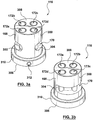
- the insert 700 includes a cylindrical body 702 having a longitudinal axis 704.
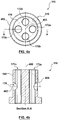
- An open distribution channel 706 is formed in an outside surface of the body 702 and follows a circumferential perimeter 708.
- the distribution channel 706 is tilted when compared with the embodiment shown in FIG. 3 , resulting in the circumferential perimeter 708 defining a generally elliptical shape, when viewed along the axis 704, that is at a non-perpendicular angle 710 to the longitudinal axis 704.
- Drop channels 712 are formed in the body 702 and intersect with the distribution channel 706.
- the tilt of the distribution channel 706 means that the drop channels 712 intersect the distribution channel 706 at different points along the longitudinal axis 704.
- a flange 714 extends from the body 702.
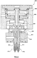
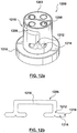
- FIG. 8 shows a portion of an injection molding apparatus 800 according to another embodiment of the present invention.
- like reference numerals in the 800 series are used to describe parts like those in FIG. 1 for ease of understanding. Only differing features and aspects of the present embodiment are described in detail. For description of the like parts, the other embodiments can be referenced. The features and aspects described for the other embodiments can be used accordingly with the present embodiment.
- the bottom plate 134 can be larger or smaller and thus can have more or fewer slots and bores.
Landscapes
- Engineering & Computer Science (AREA)
- Manufacturing & Machinery (AREA)
- Mechanical Engineering (AREA)
- Moulds For Moulding Plastics Or The Like (AREA)
Claims (24)
- Insert de répartition de matière de moulage (116) pour un canal chauffé, comprenant :un corps cylindrique (168) présentant un axe longitudinal (400),un canal de répartition (170) et une pluralité de canaux de chute directe (172) formés dans le corps (168) et coupant le canal de répartition (170), les canaux de chute directe (172) sortant du corps (168) à une première extrémité (306) du corps (168), caractérisé en ce que le canal de répartition (170) est formé sur la surface externe cylindrique (300) du corps (168), et le canal de répartition (170) présente une partie suivant le périmètre circonférentiel du corps.
- Insert de répartition de matière de moulage (116) selon la revendication 1, dans lequel le canal de répartition (170) possède une première extrémité (306) et une seconde extrémité (308),
- Insert de répartition de matière de moulage (116) selon la revendication 2, dans lequel les différents canaux de chute directe (172) sont espacés également, la première extrémité (302) du canal de répartition (170) se terminant au niveau d'un premier canal de chute directe (172a) et la seconde extrémité (34) du canal de répartition (170) se terminant au niveau d'un second canal de chute directe (172d) contigu au premier canal de chute directe (172a) après avoir coupé la totalité de la pluralité de canaux de chute directe (172).
- Insert de répartition de matière de moulage (116) selon la revendication 1, dans lequel le canal de répartition (170) circonscrit le corps cylindrique (168).
- Insert de répartition de matière de moulage (116) selon la revendication 1, dans lequel le périmètre circonférentiel est centré autour de l'axe longitudinal (400).
- Insert de répartition de matière de moulage (116) selon la revendication 5, dans lequel le périmètre circonférentiel définit un cercle auquel est normal l'axe longitudinal (400).
- Insert de répartition de matière de moulage (116) selon la revendication 1, dans lequel les canaux de chute directe (172) sortent du corps (168) au niveau de la première extrémité (306) du corps (168) et d'une seconde extrémité (308) du corps (168).
- Insert de répartition de matière de moulage (116) selon la revendication 1, dans lequel une extrémité (306, 308) du corps cylindrique (168) comprend un flasque (310).
- Insert de répartition de matière de moulage (116) selon la revendication 1, l'insert de répartition de matière de moulage (116) étant une pièce monobloc.
- Insert de répartition de matière de moulage (116) selon la revendication 1, comprenant en outre un manchon (504) apparié avec la surface externe cylindrique (300) du corps (168), le manchon (504) entourant au moins une partie du canal de répartition (170).
- Insert de répartition de matière de moulage (116) selon la revendication 1, dans lequel le canal de répartition (170) comporte au moins une jonction de dérivation (1212).
- Appareil de moulage par injection (100) comprenant :un collecteur (110) définissant un canal collecteur (148),une ou plusieurs buses (112) définissant une pluralité de canaux séparés de buses (152), la ou les buses (112) étant accouplées au collecteur (110), chacun de la pluralité de canaux de buses (152) communiquant avec l'un différent d'une pluralité d'orifices de moule (153), etl'insert de répartition de matière de moulage (116) conforme à l'une des revendications 1 à 11, accouplé au collecteur (110), le canal de répartition (170) communiquant avec le canal collecteur (148) ; et les différents canaux de chute directe (172) sont en nombre égal avec les différents canaux de buses (152), chaque canal de chute directe (172) communiquant avec l'un différent des canaux de buses (152).
- Appareil de moulage par injection (100) selon la revendication 12, dans lequel le canal de répartition (170) est un canal de répartition (170) ouvert formé sur une surface externe (300) du corps (168) et entouré par le collecteur (110).
- Appareil de moulage par injection (100) selon la revendication 12, dans lequel les canaux de chute directe (172) sortent du corps (168) aux deux extrémités (306, 308) du corps (168), l'appareil de moulage par injection comprenant en outre une pluralité de tiges de soupapes (114) s'étendant au travers des canaux de chute directe (172) et vers les orifices de moule (153).
- Appareil de moulage par injection (100) selon la revendication 14, comprenant en outre un coussinet de tige de soupape (144) s'étendant dans les canaux de chute directe (172).
- Appareil de moulage par injection (100) selon la revendication 14, comprenant en outre une plaque arrière (102) et un actionneur (104) accouplé à la plaque arrière (102).
- Appareil de moulage par injection (100) selon la revendication 14, comprenant en outre un support de tige de soupape (106) accouplé à un actionneur (104) et aux têtes des tiges de soupapes (114).
- Appareil de moulage par injection (100) selon la revendication 17, comprenant en outre au moins un goujon anti rotation (138) dont une première extrémité est accouplée au support de tige de soupape (106) et dont une seconde extrémité est disposée dans une fente (118) de la plaque arrière (102), le goujon anti rotation (138) et la fente (118) étant configurés pour limiter la rotation du support de tige de soupape (106) autour d'un axe longitudinal (140) et pour permettre la translation du support de tige de soupape (106) le long de l'axe longitudinal (140).
- Appareil de moulage par injection (100) selon la revendication 17, comprenant en outre un boulon (132) couplant un piston (126) de l'actionneur (104) au support de tige de soupape (106).
- Appareil de moulage par injection (100) selon la revendication 12, dans lequel l'insert de répartition de matière de moulage (116) est brasé, joint ou soudé au collecteur (110).
- Appareil de moulage par injection (100) selon la revendication 12, dans lequel l'insert de répartition de matière de moulage (116) est ajusté à force dans le collecteur (110).
- Appareil de moulage par injection (100) selon la revendication 12, dans lequel l'insert de répartition de matière de moulage (116) possède un manchon (504) apparié avec le corps (168), le manchon (504) entourant au moins une partie du canal de répartition (170).
- Appareil de moulage par injection (100) selon la revendication 12, dans lequel le canal de répartition (170) comporte au moins une jonction de dérivation (1212).
- Appareil de moulage par injection (100) selon l'une des revendications 12 à 23, comprenant en outre :une plaque arrière (102),un actionneur accouplé à la plaque arrière (102), le collecteur (110) étant accouplé à la plaque arrière (102), le canal de répartition (170) étant un canal de répartition (170) ouvert formé sur la surface externe (300) du corps (168) et entouré par le collecteur (110), et les différents canaux de chute directe (172) sortant du corps (168) aux deux extrémités (306, 308) du corps (168),un coussinet de tige de soupape (144) s'étendant dans les canaux de chute directe (172),une pluralité de tiges de soupapes (114) s'étendant à partir de l'actionneur (104) au travers du coussinet de tige de soupape (144) et des canaux de chute directe (172) vers les orifices de moule (153), etun support de tige de soupape (106) accouplé à l'actionneur (104) et accouplé aux têtes des tiges de soupapes (114).
Applications Claiming Priority (2)
| Application Number | Priority Date | Filing Date | Title |
|---|---|---|---|
| US11/875,318 US7618253B2 (en) | 2007-10-19 | 2007-10-19 | Multiple-gate injection molding apparatus |
| PCT/CA2008/001839 WO2009049419A1 (fr) | 2007-10-19 | 2008-10-17 | Appareil de moulage par injection à multiples orifices de coulée |
Publications (3)
| Publication Number | Publication Date |
|---|---|
| EP2200800A1 EP2200800A1 (fr) | 2010-06-30 |
| EP2200800A4 EP2200800A4 (fr) | 2011-08-24 |
| EP2200800B1 true EP2200800B1 (fr) | 2016-12-21 |
Family
ID=40563745
Family Applications (1)
| Application Number | Title | Priority Date | Filing Date |
|---|---|---|---|
| EP08840555.0A Active EP2200800B1 (fr) | 2007-10-19 | 2008-10-17 | Appareil de moulage par injection à multiples orifices de coulée |
Country Status (4)
| Country | Link |
|---|---|
| US (3) | US7618253B2 (fr) |
| EP (1) | EP2200800B1 (fr) |
| CN (1) | CN101952099B (fr) |
| WO (1) | WO2009049419A1 (fr) |
Families Citing this family (16)
| Publication number | Priority date | Publication date | Assignee | Title |
|---|---|---|---|---|
| EP2008790A2 (fr) * | 2007-06-27 | 2008-12-31 | AWM Mold Tech AG | Agencement de douille d'obturateur à aiguille |
| US7618253B2 (en) * | 2007-10-19 | 2009-11-17 | Mold-Masters (2007) Limited | Multiple-gate injection molding apparatus |
| ITBI20080006A1 (it) * | 2008-04-24 | 2009-10-25 | Thermoplay Spa | Sistema di stampaggio ad iniezione di materiale plastico, particolarmente adatto per essere associato con una unita' di soffiaggio del materiale plastico stampato. |
| CA2809788A1 (fr) * | 2010-09-13 | 2012-03-22 | Husky Injection Molding Systems Ltd. | Systeme d'outil de moulage avec ensemble actionneur comprenant un ensemble piston et un ensemble membrane souple |
| CN103442874A (zh) * | 2011-02-18 | 2013-12-11 | 赫斯基注塑系统有限公司 | 包括使每个进口与多个出口处于流体连通的一件式歧管组件的模具工具系统 |
| DE102012101754B4 (de) | 2012-03-01 | 2026-05-07 | Günther Heisskanaltechnik Gmbh | Spritzgießdüse mit von Führungsbuchsen geführten Verschlussnadeln und Spritzgießvorrichtung mit einer solchen |
| WO2014052617A1 (fr) * | 2012-09-26 | 2014-04-03 | Synventive Molding Solutions, Inc. | Dispositif de limitation de rotation de tige de soupape |
| ITAN20130197A1 (it) * | 2013-10-25 | 2015-04-26 | Ihr S R L | Gruppo di distribuzione per stampaggio ad iniezione. |
| DE102016114706A1 (de) | 2016-08-09 | 2018-02-15 | Mht Mold & Hotrunner Technology Ag | Adapterplatte sowie Spritzgießmaschine mit einer solchen |
| CN106335164A (zh) * | 2016-11-11 | 2017-01-18 | 深圳天珑无线科技有限公司 | 塑胶注入件以及塑胶模具 |
| US11780132B2 (en) * | 2017-07-14 | 2023-10-10 | Otto Männer GmbH | Injection molding device |
| US11878453B2 (en) * | 2019-07-21 | 2024-01-23 | Incoe Corporation | Leak protection bushing for hotrunner manifold assembly |
| US11396118B2 (en) * | 2019-09-23 | 2022-07-26 | Incoe Corporation | Actuator for controlling multiple injection molding valve pins |
| ES2964496T3 (es) * | 2021-03-05 | 2024-04-08 | Mold Masters 2007 Ltd | Sistema de canal de colada caliente |
| EP4506136A1 (fr) * | 2023-08-10 | 2025-02-12 | Inglass S.p.A. | Élément d'un dispositif de moulage par injection |
| JP2025043120A (ja) * | 2023-09-15 | 2025-03-28 | 株式会社東芝 | 音響信号処理装置及び音響信号処理方法 |
Family Cites Families (44)
| Publication number | Priority date | Publication date | Assignee | Title |
|---|---|---|---|---|
| CA1097872A (fr) * | 1978-12-08 | 1981-03-24 | Jobst U. Gellert | Traduction non-disponible |
| EP0021273B1 (fr) | 1979-06-12 | 1984-09-12 | Hendrikus Jacobus Elisabeth Schouenberg | Mécanisme d'injection pour mouler des matières plastiques |
| US4378963A (en) | 1980-12-11 | 1983-04-05 | Schouenberg Hendrikus J E | Injection mechanism for molding plastics |
| US4436496A (en) | 1981-06-10 | 1984-03-13 | General Electric Company | Mold for a liquid injection molding composition |
| DE3403603C2 (de) | 1984-02-02 | 1985-12-05 | Maschinenfabrik Köppern GmbH & Co KG, 4320 Hattingen | Zwangsgesteuerter Nadelverschluß für Spritzdüsen in Spritzgießformen |
| DE3642343C2 (de) | 1986-12-11 | 1997-05-28 | Arnaldo Dipl Ing Glaeser | Vorrichtung zum gleichzeitigen Anspritzen mehrerer Formteile in einem Spritzwerkzeug |
| DE3733363A1 (de) | 1987-10-02 | 1989-04-13 | Horst Prinz | Heisskanalnadelverschlussduese zur verarbeitung thermoplastischer massen |
| JPH02107417A (ja) | 1988-10-17 | 1990-04-19 | Sanri Kk | 合成樹脂射出成形機の多ゲート用チップ駒装置 |
| DE3906651A1 (de) | 1989-03-02 | 1990-09-06 | Hans Schreck | Heisskanal fuer eine kunststoffspritzmaschine |
| CA1278409C (fr) | 1989-06-30 | 1991-01-02 | Jobst Ulrich Gellert | Systeme de moulage par injection a buse d'apport double logee dans le collecteur |
| US5096411A (en) | 1990-05-17 | 1992-03-17 | Gellert Jobst U | Injection molding cast manifold |
| DE4034934C2 (de) | 1990-11-02 | 1994-03-17 | Prima Heiskanaltechnik Gmbh | Tandemdüse zum Verarbeiten von thermoplastischen Massen |
| CA2047461A1 (fr) | 1991-07-19 | 1993-01-20 | Jobst Ulrich Gellert | Distributeur de moulage par injection avec insertions amovibles |
| DE4206318C2 (de) | 1992-02-29 | 1994-06-16 | Otto Maenner | Mehrfach-Nadelverschluß-Düse für Spritzgießformen |
| US5551863A (en) | 1992-11-27 | 1996-09-03 | Polyshot Corporation | Self-contained runnerless molding system |
| DE29504162U1 (de) | 1994-07-04 | 1995-05-18 | Gaul, Herbert, 69221 Dossenheim | Nadelverschluß-Spritzdüse für Heißkanalwerkzeuge zur Verarbeitung von thermoplastischen Kunststoffen |
| DE4425981A1 (de) | 1994-07-22 | 1996-01-25 | Brandt Geb Brandt Ursula | Vorrichtung zur Herstellung von Formteilen insbesondere aus Gummi-Elastomer-Material |
| US5536164A (en) | 1995-05-05 | 1996-07-16 | Electra Form, Inc. | Flexible hot manifold assembly for injection molding machines |
| CA2164557C (fr) | 1995-12-06 | 2007-05-08 | Jobst Ulrich Gellert | Collecteur pour installation de moulage par injection |
| CA2219197C (fr) | 1997-10-23 | 2006-12-05 | Mold-Masters Limited | Appareil de moulage par injection possedant un dispositif de transfert de la matiere fondue et une douille divisant celle-ci |
| CA2219054C (fr) | 1997-10-23 | 2006-12-05 | Mold-Masters Limited | Dispositif de moulage par injection comportant des douilles divisant la matiere fondue |
| US7029268B2 (en) * | 2001-12-26 | 2006-04-18 | Synventive Molding Solutions, Inc. | Non-coaxial injection molding valve flow control |
| JP4062382B2 (ja) | 1998-07-16 | 2008-03-19 | 株式会社Ipm | バルブゲート装置 |
| US6196822B1 (en) | 1998-12-18 | 2001-03-06 | Incoe Corporation | Conversion manifold for multiple injection unit injection molding machine |
| CA2264224A1 (fr) | 1999-02-26 | 2000-08-26 | Denis Babin | Moule a injection a empreintes multiples separant la fonte a l'avant des busettes |
| DE19943797B4 (de) | 1999-09-13 | 2009-07-30 | Yudo Co., Ltd. | Kunststoffeinspritzvorrichtung für Spritzgussmaschinen mit einem Ventilsystem, das Einzelkolben-betätigte Mehrfach-Ventilstifte aufweist |
| JP2002036310A (ja) | 2000-07-25 | 2002-02-05 | Mitsubishi Materials Corp | マイクロリレー用部材の成形方法およびこの方法に用いるバルブゲート装置 |
| US6394779B1 (en) * | 2001-06-28 | 2002-05-28 | Toyo Tire & Rubber Co., Ltd. | Molding tool for molding with cylindrical core |
| CA2358148A1 (fr) * | 2001-10-03 | 2003-04-03 | Mold-Masters Limited | Buse d'injection |
| US6780003B2 (en) * | 2002-08-02 | 2004-08-24 | Mold-Masters Limited | Removable heater for a hot runner nozzle |
| DE20216125U1 (de) | 2002-10-18 | 2003-01-23 | Heitec-Heisskanaltechnik GmbH, 35099 Burgwald | Vorrichtung zum Öffnen und Schliessen von Einspritzdüsen in einem Spritzgusswerkzeug |
| US7320589B2 (en) | 2003-02-26 | 2008-01-22 | Mold-Masters (2007) Limited | Hot runner manifold plug for rheological balance in hot runner injection molding |
| DE602004013661D1 (de) * | 2003-03-21 | 2008-06-26 | Mold Masters 2007 Ltd | Spritzgiessnadelverschlussbuchse |
| US7125246B2 (en) * | 2003-10-08 | 2006-10-24 | Mold Hotrunner Solutions Inc. | Hot runner for molding small plastic articles |
| CA2475500A1 (fr) * | 2004-04-07 | 2005-10-07 | Jonathon Fischer | Injecteur a corps d'injecteur ayant des segments chauffes et non chauffes |
| DE112005001013B4 (de) | 2004-05-03 | 2019-07-11 | Mold-Masters (2007) Limited | Spritzgießvorrichtung mit einem Formverteiler mit geringem Abstand |
| JP2006007658A (ja) | 2004-06-28 | 2006-01-12 | Yamaguchi Seiki Kogyo Kk | 射出成形機における成形材供給装置 |
| KR100810667B1 (ko) | 2004-12-15 | 2008-03-07 | 허남욱 | 멀티 핫런너 밸브장치 |
| ITTO20050611A1 (it) | 2005-09-09 | 2007-03-10 | Thermoplay Spa | Commutatore del flusso di materiale plastico fuso in una piastrra calda per lo stampaggio ad iniezione |
| JP2007083661A (ja) | 2005-09-26 | 2007-04-05 | Canon Chemicals Inc | 射出成形用金型装置 |
| US7300275B2 (en) | 2005-10-26 | 2007-11-27 | Panos Trakas | Multi-point nozzle assembly |
| CN2863440Y (zh) | 2005-11-28 | 2007-01-31 | 先锐模具配件(东莞)有限公司 | 多嘴头型热流道模具 |
| ATE544573T1 (de) | 2006-12-29 | 2012-02-15 | Mold Masters 2007 Ltd | SPRITZGIEßVORRICHTUNG MIT SEITLICHER ANGUSSÖFFNUNG |
| US7618253B2 (en) * | 2007-10-19 | 2009-11-17 | Mold-Masters (2007) Limited | Multiple-gate injection molding apparatus |
-
2007
- 2007-10-19 US US11/875,318 patent/US7618253B2/en active Active
-
2008
- 2008-10-17 US US12/738,836 patent/US8152513B2/en active Active
- 2008-10-17 WO PCT/CA2008/001839 patent/WO2009049419A1/fr not_active Ceased
- 2008-10-17 CN CN200880122581.9A patent/CN101952099B/zh active Active
- 2008-10-17 EP EP08840555.0A patent/EP2200800B1/fr active Active
-
2012
- 2012-02-21 US US13/400,854 patent/US8414285B2/en active Active
Non-Patent Citations (1)
| Title |
|---|
| None * |
Also Published As
| Publication number | Publication date |
|---|---|
| US7618253B2 (en) | 2009-11-17 |
| CN101952099A (zh) | 2011-01-19 |
| CN101952099B (zh) | 2014-03-12 |
| US20120156325A1 (en) | 2012-06-21 |
| US20090104307A1 (en) | 2009-04-23 |
| US20100215795A1 (en) | 2010-08-26 |
| EP2200800A1 (fr) | 2010-06-30 |
| US8152513B2 (en) | 2012-04-10 |
| WO2009049419A1 (fr) | 2009-04-23 |
| US8414285B2 (en) | 2013-04-09 |
| EP2200800A4 (fr) | 2011-08-24 |
Similar Documents
| Publication | Publication Date | Title |
|---|---|---|
| EP2200800B1 (fr) | Appareil de moulage par injection à multiples orifices de coulée | |
| EP2639035B1 (fr) | Appareil de moulage par injection à entrée latérale | |
| EP1343619B1 (fr) | Buse pour moule a injection | |
| US8241032B2 (en) | Single level manifold for an injection molding apparatus | |
| US7658606B2 (en) | Edge gated injection molding apparatus | |
| EP2627490B1 (fr) | Système moule-outil comportant un dispositif de division de coulée comprenant des canaux de coulée continue s'étendant de l'entrée aux sorties | |
| EP2839942B1 (fr) | Agencement de joint de buse pour un appareil de moulage par injection | |
| PT1911561E (pt) | Aparelho de moldagem por co-injecção e correspondente pulverizador de canais de aquecimento | |
| EP1765568B1 (fr) | Buse de co-injection a canaux chauffants presentant des canaux thermiquement separes pour la matiere fondue | |
| EP1941984A1 (fr) | Appareil de moulage par injection avec entrées d'injection latérales | |
| CN104057584A (zh) | 用于浇铸模具的部件,浇铸模具和用于制造部件的方法 | |
| EP4045268B1 (fr) | Buse de grille latérale et moule d'injection | |
| EP0491332B1 (fr) | Bloc de distribution de matière fondue pour des cavités multiples | |
| US20240123665A1 (en) | Injection mold with a side gate nozzle | |
| KR20180016055A (ko) | 가장자리 게이트 사출 성형장치 |
Legal Events
| Date | Code | Title | Description |
|---|---|---|---|
| PUAI | Public reference made under article 153(3) epc to a published international application that has entered the european phase |
Free format text: ORIGINAL CODE: 0009012 |
|
| 17P | Request for examination filed |
Effective date: 20100414 |
|
| AK | Designated contracting states |
Kind code of ref document: A1 Designated state(s): AT BE BG CH CY CZ DE DK EE ES FI FR GB GR HR HU IE IS IT LI LT LU LV MC MT NL NO PL PT RO SE SI SK TR |
|
| AX | Request for extension of the european patent |
Extension state: AL BA MK RS |
|
| DAX | Request for extension of the european patent (deleted) | ||
| A4 | Supplementary search report drawn up and despatched |
Effective date: 20110722 |
|
| RIC1 | Information provided on ipc code assigned before grant |
Ipc: B29C 45/27 20060101ALI20110718BHEP Ipc: B29C 45/23 20060101ALI20110718BHEP Ipc: B29C 45/22 20060101AFI20110718BHEP |
|
| REG | Reference to a national code |
Ref country code: DE Ref legal event code: R079 Ref document number: 602008048040 Country of ref document: DE Free format text: PREVIOUS MAIN CLASS: B29C0045220000 Ipc: B29C0045280000 |
|
| GRAP | Despatch of communication of intention to grant a patent |
Free format text: ORIGINAL CODE: EPIDOSNIGR1 |
|
| RIC1 | Information provided on ipc code assigned before grant |
Ipc: B29C 45/28 20060101AFI20160616BHEP Ipc: B29C 45/27 20060101ALI20160616BHEP |
|
| INTG | Intention to grant announced |
Effective date: 20160629 |
|
| GRAS | Grant fee paid |
Free format text: ORIGINAL CODE: EPIDOSNIGR3 |
|
| GRAA | (expected) grant |
Free format text: ORIGINAL CODE: 0009210 |
|
| AK | Designated contracting states |
Kind code of ref document: B1 Designated state(s): AT BE BG CH CY CZ DE DK EE ES FI FR GB GR HR HU IE IS IT LI LT LU LV MC MT NL NO PL PT RO SE SI SK TR |
|
| REG | Reference to a national code |
Ref country code: GB Ref legal event code: FG4D |
|
| REG | Reference to a national code |
Ref country code: CH Ref legal event code: EP |
|
| REG | Reference to a national code |
Ref country code: IE Ref legal event code: FG4D |
|
| REG | Reference to a national code |
Ref country code: AT Ref legal event code: REF Ref document number: 855090 Country of ref document: AT Kind code of ref document: T Effective date: 20170115 |
|
| REG | Reference to a national code |
Ref country code: DE Ref legal event code: R096 Ref document number: 602008048040 Country of ref document: DE |
|
| PG25 | Lapsed in a contracting state [announced via postgrant information from national office to epo] |
Ref country code: LV Free format text: LAPSE BECAUSE OF FAILURE TO SUBMIT A TRANSLATION OF THE DESCRIPTION OR TO PAY THE FEE WITHIN THE PRESCRIBED TIME-LIMIT Effective date: 20161221 |
|
| REG | Reference to a national code |
Ref country code: LT Ref legal event code: MG4D |
|
| REG | Reference to a national code |
Ref country code: NL Ref legal event code: MP Effective date: 20161221 |
|
| PG25 | Lapsed in a contracting state [announced via postgrant information from national office to epo] |
Ref country code: NO Free format text: LAPSE BECAUSE OF FAILURE TO SUBMIT A TRANSLATION OF THE DESCRIPTION OR TO PAY THE FEE WITHIN THE PRESCRIBED TIME-LIMIT Effective date: 20170321 Ref country code: LT Free format text: LAPSE BECAUSE OF FAILURE TO SUBMIT A TRANSLATION OF THE DESCRIPTION OR TO PAY THE FEE WITHIN THE PRESCRIBED TIME-LIMIT Effective date: 20161221 Ref country code: GR Free format text: LAPSE BECAUSE OF FAILURE TO SUBMIT A TRANSLATION OF THE DESCRIPTION OR TO PAY THE FEE WITHIN THE PRESCRIBED TIME-LIMIT Effective date: 20170322 Ref country code: SE Free format text: LAPSE BECAUSE OF FAILURE TO SUBMIT A TRANSLATION OF THE DESCRIPTION OR TO PAY THE FEE WITHIN THE PRESCRIBED TIME-LIMIT Effective date: 20161221 |
|
| REG | Reference to a national code |
Ref country code: AT Ref legal event code: MK05 Ref document number: 855090 Country of ref document: AT Kind code of ref document: T Effective date: 20161221 |
|
| PG25 | Lapsed in a contracting state [announced via postgrant information from national office to epo] |
Ref country code: HR Free format text: LAPSE BECAUSE OF FAILURE TO SUBMIT A TRANSLATION OF THE DESCRIPTION OR TO PAY THE FEE WITHIN THE PRESCRIBED TIME-LIMIT Effective date: 20161221 Ref country code: FI Free format text: LAPSE BECAUSE OF FAILURE TO SUBMIT A TRANSLATION OF THE DESCRIPTION OR TO PAY THE FEE WITHIN THE PRESCRIBED TIME-LIMIT Effective date: 20161221 |
|
| PG25 | Lapsed in a contracting state [announced via postgrant information from national office to epo] |
Ref country code: NL Free format text: LAPSE BECAUSE OF FAILURE TO SUBMIT A TRANSLATION OF THE DESCRIPTION OR TO PAY THE FEE WITHIN THE PRESCRIBED TIME-LIMIT Effective date: 20161221 |
|
| PG25 | Lapsed in a contracting state [announced via postgrant information from national office to epo] |
Ref country code: RO Free format text: LAPSE BECAUSE OF FAILURE TO SUBMIT A TRANSLATION OF THE DESCRIPTION OR TO PAY THE FEE WITHIN THE PRESCRIBED TIME-LIMIT Effective date: 20161221 Ref country code: IS Free format text: LAPSE BECAUSE OF FAILURE TO SUBMIT A TRANSLATION OF THE DESCRIPTION OR TO PAY THE FEE WITHIN THE PRESCRIBED TIME-LIMIT Effective date: 20170421 Ref country code: EE Free format text: LAPSE BECAUSE OF FAILURE TO SUBMIT A TRANSLATION OF THE DESCRIPTION OR TO PAY THE FEE WITHIN THE PRESCRIBED TIME-LIMIT Effective date: 20161221 Ref country code: SK Free format text: LAPSE BECAUSE OF FAILURE TO SUBMIT A TRANSLATION OF THE DESCRIPTION OR TO PAY THE FEE WITHIN THE PRESCRIBED TIME-LIMIT Effective date: 20161221 Ref country code: CZ Free format text: LAPSE BECAUSE OF FAILURE TO SUBMIT A TRANSLATION OF THE DESCRIPTION OR TO PAY THE FEE WITHIN THE PRESCRIBED TIME-LIMIT Effective date: 20161221 |
|
| PG25 | Lapsed in a contracting state [announced via postgrant information from national office to epo] |
Ref country code: PT Free format text: LAPSE BECAUSE OF FAILURE TO SUBMIT A TRANSLATION OF THE DESCRIPTION OR TO PAY THE FEE WITHIN THE PRESCRIBED TIME-LIMIT Effective date: 20170421 Ref country code: IT Free format text: LAPSE BECAUSE OF FAILURE TO SUBMIT A TRANSLATION OF THE DESCRIPTION OR TO PAY THE FEE WITHIN THE PRESCRIBED TIME-LIMIT Effective date: 20161221 Ref country code: PL Free format text: LAPSE BECAUSE OF FAILURE TO SUBMIT A TRANSLATION OF THE DESCRIPTION OR TO PAY THE FEE WITHIN THE PRESCRIBED TIME-LIMIT Effective date: 20161221 Ref country code: AT Free format text: LAPSE BECAUSE OF FAILURE TO SUBMIT A TRANSLATION OF THE DESCRIPTION OR TO PAY THE FEE WITHIN THE PRESCRIBED TIME-LIMIT Effective date: 20161221 Ref country code: BE Free format text: LAPSE BECAUSE OF FAILURE TO SUBMIT A TRANSLATION OF THE DESCRIPTION OR TO PAY THE FEE WITHIN THE PRESCRIBED TIME-LIMIT Effective date: 20161221 Ref country code: ES Free format text: LAPSE BECAUSE OF FAILURE TO SUBMIT A TRANSLATION OF THE DESCRIPTION OR TO PAY THE FEE WITHIN THE PRESCRIBED TIME-LIMIT Effective date: 20161221 Ref country code: BG Free format text: LAPSE BECAUSE OF FAILURE TO SUBMIT A TRANSLATION OF THE DESCRIPTION OR TO PAY THE FEE WITHIN THE PRESCRIBED TIME-LIMIT Effective date: 20170321 |
|
| REG | Reference to a national code |
Ref country code: DE Ref legal event code: R097 Ref document number: 602008048040 Country of ref document: DE |
|
| PLBE | No opposition filed within time limit |
Free format text: ORIGINAL CODE: 0009261 |
|
| STAA | Information on the status of an ep patent application or granted ep patent |
Free format text: STATUS: NO OPPOSITION FILED WITHIN TIME LIMIT |
|
| 26N | No opposition filed |
Effective date: 20170922 |
|
| PG25 | Lapsed in a contracting state [announced via postgrant information from national office to epo] |
Ref country code: DK Free format text: LAPSE BECAUSE OF FAILURE TO SUBMIT A TRANSLATION OF THE DESCRIPTION OR TO PAY THE FEE WITHIN THE PRESCRIBED TIME-LIMIT Effective date: 20161221 |
|
| PG25 | Lapsed in a contracting state [announced via postgrant information from national office to epo] |
Ref country code: SI Free format text: LAPSE BECAUSE OF FAILURE TO SUBMIT A TRANSLATION OF THE DESCRIPTION OR TO PAY THE FEE WITHIN THE PRESCRIBED TIME-LIMIT Effective date: 20161221 |
|
| PG25 | Lapsed in a contracting state [announced via postgrant information from national office to epo] |
Ref country code: MC Free format text: LAPSE BECAUSE OF FAILURE TO SUBMIT A TRANSLATION OF THE DESCRIPTION OR TO PAY THE FEE WITHIN THE PRESCRIBED TIME-LIMIT Effective date: 20161221 |
|
| REG | Reference to a national code |
Ref country code: CH Ref legal event code: PL |
|
| GBPC | Gb: european patent ceased through non-payment of renewal fee |
Effective date: 20171017 |
|
| REG | Reference to a national code |
Ref country code: IE Ref legal event code: MM4A |
|
| REG | Reference to a national code |
Ref country code: FR Ref legal event code: ST Effective date: 20180629 |
|
| PG25 | Lapsed in a contracting state [announced via postgrant information from national office to epo] |
Ref country code: LI Free format text: LAPSE BECAUSE OF NON-PAYMENT OF DUE FEES Effective date: 20171031 Ref country code: CH Free format text: LAPSE BECAUSE OF NON-PAYMENT OF DUE FEES Effective date: 20171031 Ref country code: GB Free format text: LAPSE BECAUSE OF NON-PAYMENT OF DUE FEES Effective date: 20171017 Ref country code: LU Free format text: LAPSE BECAUSE OF NON-PAYMENT OF DUE FEES Effective date: 20171017 |
|
| PG25 | Lapsed in a contracting state [announced via postgrant information from national office to epo] |
Ref country code: FR Free format text: LAPSE BECAUSE OF NON-PAYMENT OF DUE FEES Effective date: 20171031 |
|
| PG25 | Lapsed in a contracting state [announced via postgrant information from national office to epo] |
Ref country code: MT Free format text: LAPSE BECAUSE OF NON-PAYMENT OF DUE FEES Effective date: 20171017 |
|
| PG25 | Lapsed in a contracting state [announced via postgrant information from national office to epo] |
Ref country code: IE Free format text: LAPSE BECAUSE OF NON-PAYMENT OF DUE FEES Effective date: 20171017 |
|
| PG25 | Lapsed in a contracting state [announced via postgrant information from national office to epo] |
Ref country code: HU Free format text: LAPSE BECAUSE OF FAILURE TO SUBMIT A TRANSLATION OF THE DESCRIPTION OR TO PAY THE FEE WITHIN THE PRESCRIBED TIME-LIMIT; INVALID AB INITIO Effective date: 20081017 |
|
| PG25 | Lapsed in a contracting state [announced via postgrant information from national office to epo] |
Ref country code: CY Free format text: LAPSE BECAUSE OF NON-PAYMENT OF DUE FEES Effective date: 20161221 |
|
| PG25 | Lapsed in a contracting state [announced via postgrant information from national office to epo] |
Ref country code: TR Free format text: LAPSE BECAUSE OF FAILURE TO SUBMIT A TRANSLATION OF THE DESCRIPTION OR TO PAY THE FEE WITHIN THE PRESCRIBED TIME-LIMIT Effective date: 20161221 |
|
| PGFP | Annual fee paid to national office [announced via postgrant information from national office to epo] |
Ref country code: DE Payment date: 20250923 Year of fee payment: 18 |