EP2201217B1 - Method and device for positional stabilising of tunnel lining elements - Google Patents
Method and device for positional stabilising of tunnel lining elements Download PDFInfo
- Publication number
- EP2201217B1 EP2201217B1 EP07703077A EP07703077A EP2201217B1 EP 2201217 B1 EP2201217 B1 EP 2201217B1 EP 07703077 A EP07703077 A EP 07703077A EP 07703077 A EP07703077 A EP 07703077A EP 2201217 B1 EP2201217 B1 EP 2201217B1
- Authority
- EP
- European Patent Office
- Prior art keywords
- tunnel
- elements
- bracing
- fact
- construction
- Prior art date
- Legal status (The legal status is an assumption and is not a legal conclusion. Google has not performed a legal analysis and makes no representation as to the accuracy of the status listed.)
- Not-in-force
Links
- 238000000034 method Methods 0.000 title claims abstract description 17
- 230000003019 stabilising effect Effects 0.000 title abstract 3
- 238000010276 construction Methods 0.000 claims abstract description 40
- 230000005291 magnetic effect Effects 0.000 claims abstract description 4
- 230000002787 reinforcement Effects 0.000 claims abstract description 3
- 230000006641 stabilisation Effects 0.000 claims description 20
- 229910000831 Steel Inorganic materials 0.000 claims description 5
- 238000004873 anchoring Methods 0.000 claims description 5
- 239000010959 steel Substances 0.000 claims description 5
- 238000002347 injection Methods 0.000 claims description 4
- 239000007924 injection Substances 0.000 claims description 4
- 238000012546 transfer Methods 0.000 claims description 3
- 229910001018 Cast iron Inorganic materials 0.000 claims description 2
- 230000005294 ferromagnetic effect Effects 0.000 claims description 2
- 238000005553 drilling Methods 0.000 claims 2
- 229920000297 Rayon Polymers 0.000 claims 1
- 239000012530 fluid Substances 0.000 claims 1
- 238000011105 stabilization Methods 0.000 description 12
- 230000005641 tunneling Effects 0.000 description 8
- 239000011435 rock Substances 0.000 description 7
- 241000276425 Xiphophorus maculatus Species 0.000 description 5
- 230000015572 biosynthetic process Effects 0.000 description 5
- 238000005755 formation reaction Methods 0.000 description 5
- 230000000087 stabilizing effect Effects 0.000 description 5
- 239000004575 stone Substances 0.000 description 5
- 239000000463 material Substances 0.000 description 4
- 244000089486 Phragmites australis subsp australis Species 0.000 description 3
- 238000005520 cutting process Methods 0.000 description 3
- 239000004570 mortar (masonry) Substances 0.000 description 3
- XLYOFNOQVPJJNP-UHFFFAOYSA-N water Substances O XLYOFNOQVPJJNP-UHFFFAOYSA-N 0.000 description 3
- 238000009434 installation Methods 0.000 description 2
- 238000004519 manufacturing process Methods 0.000 description 2
- 239000002689 soil Substances 0.000 description 2
- 230000006978 adaptation Effects 0.000 description 1
- 238000005452 bending Methods 0.000 description 1
- 239000004568 cement Substances 0.000 description 1
- 238000006243 chemical reaction Methods 0.000 description 1
- 239000004567 concrete Substances 0.000 description 1
- 238000012937 correction Methods 0.000 description 1
- 230000006378 damage Effects 0.000 description 1
- 230000007423 decrease Effects 0.000 description 1
- 230000003111 delayed effect Effects 0.000 description 1
- 238000013461 design Methods 0.000 description 1
- 238000011161 development Methods 0.000 description 1
- 230000029087 digestion Effects 0.000 description 1
- 238000006073 displacement reaction Methods 0.000 description 1
- 230000000694 effects Effects 0.000 description 1
- 230000002349 favourable effect Effects 0.000 description 1
- 230000009969 flowable effect Effects 0.000 description 1
- 239000006260 foam Substances 0.000 description 1
- 230000005484 gravity Effects 0.000 description 1
- 239000007788 liquid Substances 0.000 description 1
- 238000005259 measurement Methods 0.000 description 1
- 238000003801 milling Methods 0.000 description 1
- 230000000116 mitigating effect Effects 0.000 description 1
- 239000000203 mixture Substances 0.000 description 1
- 229920003023 plastic Polymers 0.000 description 1
- 239000004033 plastic Substances 0.000 description 1
- 239000011148 porous material Substances 0.000 description 1
- 230000036316 preload Effects 0.000 description 1
- 238000003825 pressing Methods 0.000 description 1
- 238000012545 processing Methods 0.000 description 1
- 230000000750 progressive effect Effects 0.000 description 1
- 230000001681 protective effect Effects 0.000 description 1
- 239000011150 reinforced concrete Substances 0.000 description 1
- 238000010079 rubber tapping Methods 0.000 description 1
- 238000007789 sealing Methods 0.000 description 1
- 238000005204 segregation Methods 0.000 description 1
- 238000010008 shearing Methods 0.000 description 1
- 238000007711 solidification Methods 0.000 description 1
- 230000008023 solidification Effects 0.000 description 1
- 239000000243 solution Substances 0.000 description 1
- 239000004094 surface-active agent Substances 0.000 description 1
- 239000000725 suspension Substances 0.000 description 1
- 210000005239 tubule Anatomy 0.000 description 1
- 239000013585 weight reducing agent Substances 0.000 description 1
Images



Classifications
-
- E—FIXED CONSTRUCTIONS
- E21—EARTH OR ROCK DRILLING; MINING
- E21D—SHAFTS; TUNNELS; GALLERIES; LARGE UNDERGROUND CHAMBERS
- E21D11/00—Lining tunnels, galleries or other underground cavities, e.g. large underground chambers; Linings therefor; Making such linings in situ, e.g. by assembling
- E21D11/04—Lining with building materials
- E21D11/08—Lining with building materials with preformed concrete slabs
- E21D11/083—Methods or devices for joining adjacent concrete segments
-
- E—FIXED CONSTRUCTIONS
- E21—EARTH OR ROCK DRILLING; MINING
- E21D—SHAFTS; TUNNELS; GALLERIES; LARGE UNDERGROUND CHAMBERS
- E21D11/00—Lining tunnels, galleries or other underground cavities, e.g. large underground chambers; Linings therefor; Making such linings in situ, e.g. by assembling
- E21D11/04—Lining with building materials
- E21D11/12—Temporary supports for use during building; Accessories
-
- E—FIXED CONSTRUCTIONS
- E21—EARTH OR ROCK DRILLING; MINING
- E21D—SHAFTS; TUNNELS; GALLERIES; LARGE UNDERGROUND CHAMBERS
- E21D11/00—Lining tunnels, galleries or other underground cavities, e.g. large underground chambers; Linings therefor; Making such linings in situ, e.g. by assembling
- E21D11/40—Devices or apparatus specially adapted for handling or placing units of linings or supporting units for tunnels or galleries
Definitions
- the invention relates to a method for the stabilization of position of a tunnel tube offset tunnel construction elements, in particular tubbing, after the displacement and the Vor-direction thereto with a support structure, according to the preamble of the first method claim and the first device claim.
- Tunnel boring machines facilitate propulsion even in poor, brittle soils and enable a high degree of mechanization in tunneling.
- the design and details of the construction of the machines are prepared for each site on the soil digestion results of geologists and hydrologists, according to the experience of the manufacturers of milling, trailing equipment, tubbing, and construction adapted. Nevertheless, in this hundreds of thousands or millions of tons of outbreak material comprehensive construction projects surprising problems that are referred to as subsoil risk can not be excluded.
- the cylindrical shield in which the drives of the cutting wheel, the transfer equipment for the excavated debris and the jacking cylinders for the jacking are arranged.
- the rear part of the shield, the tail shield consists of a cylindrical pipe jacket with a length larger than the maximum dimension of the segments, in which a hydraulic manipulator, called Erector, with which the segments are made into a complete ring, with the closing block of 360 ° and connected to the already built-in pre-filled ring of Tubbingen.
- the newly installed tubbing ring leaves the shield tail, from which it is stabilized.
- the annulus between the inner contour of the milled out mountains and the outer diameter of the tubbing ring released and it may, depending on the milled material in addition to breakouts or caverns around the shield of the machine form or have formed.
- Mitigation can be achieved in some rock types by creating a protective screen by pre-injecting through holes through flat-angled openings in the shield of the tunnel boring machine.
- This requires injectability and a necessary setting time.
- Radial anchoring can remedy where this measure is not possible, but does not solve the problem of uneven backfilling and support of the segments and takes time and is expensive.
- the stable support of the segments can be achieved in those that are not provided for screwing only by additional, doweled on the tubbing steel support rings, several per meter, and tie rods and lashing and busbar, their subsequent disassembly, after stabilization of each tubbing ring, because of is necessary for the wake of the tunnel boring machine and takes a lot of time, slows down the propulsion.
- the object of the invention is to increase the tunneling performance of a tunnel boring machine in difficult or unexpectedly rugged rock formations with fault zones, the method for position stabilization by a quasi-virtual extension of the shield tail of the tunnel boring machine and a device for exercising this new To provide a method by which the disadvantages described above are eliminated.
- the inventive method intervenes, by means of one, on the blocks of the tunnel wall from the inside acting vacuum by vacuum, with the one Traction is transmitted, which is evenly distributed on the segments of a row of rings and exercised by tension elements.
- This negative pressure acts on the inner surfaces of the tubbings by means of suitable vacuum plates, as long as the newly manufactured tunnel section is still unstable and forms an apparent extension of the shield tail, which accordingly has no wall thickness.
- the inventive method for stabilizing the position of tunnel tunneling elements displaced to a tunnel tube via the tailpipe of the tunneling shield of a tunnel boring machine, subsequent track in which the backfilling and stabilization takes place uses a support structure releasably connectable to the tunneling elements on their inner surfaces to exert a tensile force.
- This tensile force is directed substantially radially symmetrically in the tunnel tube and is exerted by tension elements.
- the tunnel expansion elements of a ring are held in the predetermined position, until the stabilization of the respective ring, the detachable connection between the Tunnelausbauriin and the multi-member mounting structure, by negative pressure relative to the outer air pressure or by, acting on the reinforcement of the Tunnelausbauimplantation, magnetic field is, which allows the desired position freely.
- the tensile force in the form of several tensile forces, is exerted as evenly distributed acting on the individual tunnel lining elements of the tunnel tube, the sizes of the tensile forces are respectively adapted to those areas in which the backfilling must be done to stabilize the tunnel tube and after stabilization of which the action of these tensile forces can be stopped.
- Support structure (5) with the negative pressure of, on the support structure (5) mounted switchable suction plates / vacuum lifter (9) or magnetically switchable magnet, on the support structure (5) is generated, these in turn held by support members (6) and supported is, because it is the progressive expansion without delay by outs and internals possible.
- the holding elements acting on the support structure consist of hydraulic cylinders, their operation with the hydraulic system which is always present on large machines is possible and their adjustment can be made quickly and very accurately.
- the device for stabilizing position of the tunnel construction elements is mounted on an adjustable support structure, which is supported by the shield of the tunnel boring machine head or the front part of its tail or by a bridge between these parts.
- a particularly space-saving self-propelled or intermittently Vietnamese arrangement is possible if the support structure is placed either on longitudinal rails in the dome, preferably sharing of existing rails, such as the carriage carriage near the ridge or the erector in the tail shield.
- the most favorable working arrangement is obtained when the support structure, during the propulsion stroke of the tunnel boring drill head, against the moving sign or the caster, is movably supported and oriented exclusively to the already stable tunnel tube, to avoid movements of the tunnel components on the not yet stabilized segments are to be transmitted.
- the support structure is equipped with sensors and proportional controls, with which deviations from the ideal shape and ideal position of the tunnel tube or changes in the preload forces can be automatically measured and, if necessary, corrected.
- the support structure can also be equipped with extendable and preferably expandable, centering, in particular with separately operable inner counter-cone, for quick, accurate and easy positioning and to improve the safety, the slip resistance in sudden stresses occurring.
- the support structure and the tubbing rings is thus given an additional form-fitting hold and about in the case of a strong Kavernenverbruches slipping of the support structure is prevented by shearing the suction plates or the magnets.
- the support structure may comprise retaining elements made of ropes, chains or tension rods or redirecting the tensile forces can be done with a support structure with which the position of the direct force axes, in the center axis of the tunnel boring machine, together with their Rajaggegaten is bypassed.
- a temporary treatment of the tunnel lining elements, in particular segments, with a highly viscous liquid can be made, with which they are sealed, which also closed an open-pore surface on the inner surface of the tunnel lining elements can be.
- the shell of a tunnel tube which is fragile compared to the mountain massif, and in particular a ring from Tübbingen, can hardly collapse due to external forces as long as the circular cross-section is maintained, because the solidly reinforced concrete withstands enormous pressures. If, in the absence of pressure from the outside, the bulging of the tubbing ring, even punctiform, is made possible, then the stability in all directions decreases abruptly by polygonal or egg-shaped formation of the tunnel tube cross-section and it can not oppose any slight pressure from the inside or from the outside more resistance become.
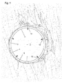
- Fig.1 the cross-section through a tunnel tube (1) is shown, which consists of tunnel construction elements (2) in the form of segments, which are assembled in a circular ring, with a bottom embedded in a bedding stone (3).
- the segments are strung together with crowned end faces and close close to the already pre-filled previous ring of Tübbingen.
- the reason for the insufficient filling is the schistige strong brittle nature of the mountains through which it comes to collapse collapses, while the material completely displaced the way for the backfill, thereby preventing the construction of a uniform external pressure on the tunnel tube 1.
- Fig.2 shown, in which it is shown how the tunnel structure elements 2 buckle right due to lack of resistance to the outside and then up inwards, which can lead to destruction, if not, as in
- Fig. 3 is shown, by installation a support structure 5, in the form of a steel frame, which is connected to the tubbing of tunnel construction elements 2 with a very large number of dowels 4 and with at least one holding element 6 for a ring of tubbing, as a tie rod or pull rope through Traction be held in the circular ring position.
- a support structure 5 in the form of a steel frame, which is connected to the tubbing of tunnel construction elements 2 with a very large number of dowels 4 and with at least one holding element 6 for a ring of tubbing, as a tie rod or pull rope through Traction be held in the circular ring position.
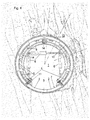
- the inventive support structure 5 now consists of several articulated parts, the suction plates 9 are positioned and held by holding elements 6, are fixed by vacuum on the inner surface 7 of the tubbings, with centering pins 14 are inserted into holes in the tubbings and thus the exact location of the suction plates. 9 Secure the support structure 5.
- the tensile force for securing the position of the tunnel lining elements 5 is generated with the holding elements 6, which can exert a uniform and finely graded and rapidly adjustable force as a hydraulic cylinder. These also serve to collapse the support structure 5 when moving after stabilization of a section of the tunnel tube 1.
- the support structure 5 extends over a large portion of the ring of the segments, wherein the bottom portion of both sides of the wedge stone 3 requires no support force, and is based on both sides of support brackets 11, which are bolted into the tubbing.
- Fig. 5 shows the same arrangement of a support structure 5, which is not yet connected to the Tunnelausbauriin 2. This is supported by a frame 16 which is movable with wheels on a rail 15 and arranged in the ridge area of the tunnel tube 1, to have underneath space for the components of the tunnel boring machine and still be with their propulsion with movable.
Landscapes
- Engineering & Computer Science (AREA)
- Structural Engineering (AREA)
- Mining & Mineral Resources (AREA)
- Architecture (AREA)
- Civil Engineering (AREA)
- Life Sciences & Earth Sciences (AREA)
- General Life Sciences & Earth Sciences (AREA)
- Geochemistry & Mineralogy (AREA)
- Geology (AREA)
- Lining And Supports For Tunnels (AREA)
- Excavating Of Shafts Or Tunnels (AREA)
Abstract
Description
Die Erfindung betrifft ein Verfahren zur Lagestabilisierung von zu einer Tunnelröhre versetzten Tunnelausbauelementen, insbesondere Tübbingen, nach dem Versetzen und die Vor-richtung dazu mit einer Halterungskonstruktion, nach dem Oberbegriff des ersten Verfahrensanspruches und des ersten Vorrichtungsanspruches.The invention relates to a method for the stabilization of position of a tunnel tube offset tunnel construction elements, in particular tubbing, after the displacement and the Vor-direction thereto with a support structure, according to the preamble of the first method claim and the first device claim.
Tunnelbohrmaschinen erleichtern den Vortrieb auch in schlechten, brüchigen Böden und ermöglichen einen hohen Mechanisierungsgrad im Tunnelbau. Die Bauweise und die Einzelheiten der Bauausführung der Maschinen werden für jede Baustelle an die Bodenaufschluß-Ergebnisse der Geologen und Hydrologen, nach den Erfahrungswerten der Hersteller von Fräsen, Nachlaufeinrichtungen, Tübbingen, sowie der Bauunternehmungen angepasst, hergestellt. Dennoch sind bei diesem hunderttausende oder Millionen Tonnen an Ausbruchmaterial umfassenden Bauvorhaben über-raschend auftretende Probleme, die als Baugrundrisiko bezeichnet werden, nicht auszuschließen.Tunnel boring machines facilitate propulsion even in poor, brittle soils and enable a high degree of mechanization in tunneling. The design and details of the construction of the machines are prepared for each site on the soil digestion results of geologists and hydrologists, according to the experience of the manufacturers of milling, trailing equipment, tubbing, and construction adapted. Nevertheless, in this hundreds of thousands or millions of tons of outbreak material comprehensive construction projects surprising problems that are referred to as subsoil risk can not be excluded.
Bei Tunnelbohrmaschinen mit Schild, für den Tunnelausbau mit Tübbingen, befindet sich hinter dem Schneidrad der zylindrische Schild, in dem die Antriebe des Schneidrades, die Übergabeeinrichtungen für den abgebauten Schutt und die Presszylinder für den Vortrieb angeordnet sind. Der hintere Teil des Schildes, der Schildschwanz, besteht aus einem zylindrischen Rohrmantel mit einer Länge, größer als die maximale Abmessung der Tübbinge, in dem ein hydraulischer Manipulator, Erektor genannt, mit dem die Tübbinge zu einem vollständigen Ring, mit dem Schlusstein von 360° zusammengesetzt und an den bereits vorher eingebauten hinterfüllten Ring aus Tübbingen angeschlossen wird.In the case of tunnel boring machines with shields, for tunnel construction with segments, behind the cutting wheel is the cylindrical shield in which the drives of the cutting wheel, the transfer equipment for the excavated debris and the jacking cylinders for the jacking are arranged. The rear part of the shield, the tail shield, consists of a cylindrical pipe jacket with a length larger than the maximum dimension of the segments, in which a hydraulic manipulator, called Erector, with which the segments are made into a complete ring, with the closing block of 360 ° and connected to the already built-in pre-filled ring of Tubbingen.
Bei bestimmten geologischen Formationen oder bei der Notwendigkeit zur Abdichtung wird häufig eine Diagonalverschrau-bung der Tübbinge eines Ringes und der benachbarten Ringe vorgenommen oder eine Verbolzung, Verzapfung oder derglei-chen, um beim folgenden Austritt aus dem Schildschwanz die hergestellte, stabile Kreisposition sicherzustellen.For certain geological formations, or where sealing is required, diagonal engagement of the segments of a ring and adjacent rings is often made, or bolting, tapping or the like, to ensure the established stable circular position upon subsequent exit from the shield tail.
Nach erfolgter Verfestigung der Umgebung und der Verfüllung von Hohlräumen, kann zumeist bereits mehrere Meter dahinter der Rückbau erfolgen und die verbauten Sicherungsteile abgenommen und wiederverwendet werden.After solidification of the environment and the backfilling of cavities, can usually be done several yards behind the demolition and removed the built-in security parts and reused.
Diese Arbeitsweise ist jedoch mit erheblichem Arbeits- und Zeitaufwand verbunden.However, this procedure is associated with considerable labor and time.
Es müssen nachträglich alle Schraubenlöcher verschlossen werden, wegen der zahlreichen Flansche, Hülsen, Platten Bewehrungsanbindungen usf. sind damit Mehrkosten für die Herstellung der Tübbinge und für den zusätzlichen Zeitaufwand der Bearbeitung verbunden.It must subsequently be closed all screw holes, because of the numerous flanges, sleeves, plates rebar connections, etc. are thus associated with additional costs for the production of the segments and for the additional time required for processing.
Bei großen Tunnelbauten und vor allem mit großen Röhrendurchmessern werden große, breite Tübbinge mit balligen Fugen verwendet, die als Drehgelenke wirken, wodurch bei lokalen Abweichungen von der Kreisform der Tunnelröhre keine Abplatzungen oder Überbeanspruchungen erfolgen. Erkauft wird dies mit einer geringeren Formschlüssigkeit der Tübbinge untereinander.In large tunnels and especially with large tube diameters large, wide segments are used with spherical joints, which act as hinges, which occur in local deviations from the circular shape of the tunnel tube no chipping or overstressing. This is bought with a lower form-fitting of the segments with each other.
Sobald sich die Tunnelbohrmaschinean dem jüngsten montierten Tübbingring in Vortriebsrichtung abstützt und den nächsten Vortriebshub mit Schneidrad und Schild samt Nachlauf durchführt, verlässt der neu angebrachte Tübbingring den Schildschwanz, von dem er stabilisiert wird. Dabei der Ringraum zwischen der Innenkontur des ausgefrästen Gebirges und dem Außendurchmesser des Tübbingringes freigegeben und es können sich je nach dem gefrästen Material zusätzlich Ausbrüche oder Kavernen rund um das Schild der Maschine bilden oder gebildet haben.Once the tunnel boring machine is supported on the youngest mounted tubbing ring in the forward drive direction and the next Propulsion stroke with cutting wheel and shield complete with caster, the newly installed tubbing ring leaves the shield tail, from which it is stabilized. In this case, the annulus between the inner contour of the milled out mountains and the outer diameter of the tubbing ring released and it may, depending on the milled material in addition to breakouts or caverns around the shield of the machine form or have formed.
Es wird deshalb zeitgleich gut fließfähiger Perlkies zur Verfüllung durch Bohrungen in den Tübbingen eingeblasen oder ein Gemisch aus Perlkies, Zement, Betonsuspension, Schäumen, Tensiden, Kunststoffen oder Mörtel usf. eingepresst. Dadurch wird das kreisrunde Tübbinggewölbe von außen am umgebenden Berg formschlüssig durch Kämpferbildung abgestützt und stabil gehalten.It is therefore at the same time injected good flowable Perlkies for backfilling through holes in the tubbings or a mixture of Perlkies, cement, concrete suspension, foams, surfactants, plastics or mortar, etc. pressed. As a result, the circular tubbing vault from the outside of the surrounding mountain is positively supported by fighters formation and kept stable.
Kommt nun der unmittelbaren Hinterfüllung ein Verbruch oder das Nachbröckeln von nicht rieselfähigen, schiefrigen, plattigen, sperrigen zuvor, werden die Fließwege für den Perlkies verklaust und verstopfen sich, aber auch Klüfte zum Einströmen von Verpressmaterial.If the immediate backfilling is followed by a break or the after-crumbling of non-free-flowing, schistose, platy, bulky ones, the flow paths for the pearl gravel are blocked and clogged, as well as crevices for the inflow of grouting material.
Bei plattenförmigen Felsformationen werden entstandene Hohlräume und Seigerungen im Kämpferbereich der Ulme und rund um das Tunnelgewölbe abgedichtet und sind nur mittels aufwendiger Bohrinjektionen zu verfüllen, was viel Zeit erfordert, in der das Gebirge seine Hinterfüllungsarbeit mittels Schwerkraft und Wasser fortsetzt.In plate-shaped rock formations resulting cavities and segregations are sealed in the militant area of the elm and around the tunnel vault and are to be filled only by means of elaborate Bohrinjektionen, which requires a lot of time in which the mountains continue its backfilling by gravity and water.
Währenddessen müssen die Tübbinge, auch außerhalb des Schildschwanzes, in der Solllage stabil gehalten werden müssen, damit die Kreisform nicht verloren geht; wendet man Einpressen von Mörtel durch Bohrungen im Schildschwanz an, dann tritt das Problem der notwendigen Verzögerung der Abbindezeit und des damit verzögertem Vortriebes auf.Meanwhile, the segments, even outside the shield tail, must be kept stable in the desired position, so that the circular shape is not lost; If one applies grouting of mortar through holes in the tail shield, then the problem of the necessary delay of the setting time and thus delayed propulsion occurs.
Tritt im ungünstigen Fall weiterer Verbruch nach bereits erfolgter, meterhoher Kavernenbildung mit entsprechend dynamischer Beaufschlagung der Firststeine durch das herabbrechende Gebirge auf, können bei ungenügend hinterfüllte Ulmsteinen oder Hohlräumen im Gebirge, die Tübbingringe eioder polygonförmig verformt werden, die Tübbingringe verrutschen und auch Sohl- oder Schlussteine oder die Tunnelröhre um mehrere cm absinken. Es kann auch, bei seitlicher Aufweitung der Ulme, der Tübbingbogen kollabieren.Occurs in the unfavorable case further break after already done, meter-high cavitation with corresponding dynamic loading of the ridge stones through the falling mountains, in insufficiently backfilled Ulmsteinen or cavities in the mountains, the Tübbingringe eioder polygonal deformed slip the tubbing rings and even sole or Schlussteine or the tunnel tube drop by several cm. It can also, with lateral expansion of the elm, collapse the tubule arch.
Eine Milderung kann bei manchen Gebirgsarten dadurch erreicht werden, indem durch Voraus-Injizieren durch Bohrungen durch flachwinklige Öffnungen im Schild der Tunnelbohrmaschine ein Schutzschirm erzeugt wird. Dies erfordert aber Injizierbarkeit und eine notwendige Abbindezeit. Radiales Verankern kann dort wo diese Maßnahme nicht möglich ist Abhilfe schaffen, löst aber nicht das Problem ungleichmäßiger Hinterfüllung und Abstützung der Tübbinge und erfordert Zeit und ist teuer.Mitigation can be achieved in some rock types by creating a protective screen by pre-injecting through holes through flat-angled openings in the shield of the tunnel boring machine. However, this requires injectability and a necessary setting time. Radial anchoring can remedy where this measure is not possible, but does not solve the problem of uneven backfilling and support of the segments and takes time and is expensive.
Die stabile Halterung der Tübbinge kann bei solchen, die nicht zur Verschraubung vorgesehen sind nur durch zusätzliche, innen an die Tübbinge angedübelte Stahlträgerringe, mehrere pro Meter, und Zuganker und Verlaschung und Verschienung erreicht werden, deren nachträgliche Demontage, nach Stabilisierung jedes Tübbingringes, wegen des für den Nachlauf der Tunnelbohrmaschine notwendig ist und viel Zeit beanspruchend, den Vortrieb verlangsamt.The stable support of the segments can be achieved in those that are not provided for screwing only by additional, doweled on the tubbing steel support rings, several per meter, and tie rods and lashing and busbar, their subsequent disassembly, after stabilization of each tubbing ring, because of is necessary for the wake of the tunnel boring machine and takes a lot of time, slows down the propulsion.
Aufgabe der Erfindung ist es, zur Erhöhung der Vortriebsleistung einer Tunnelbohrmaschine in schwierigen oder unerwartet klüftig beschaffenen Felsformationen mit Störzonen, das Verfahren zur Lagestabilisierung durch eine quasi virtuelle Verlängerung des Schildschwanzes der Tunnelbohrmaschine und eine Vorrichtung zur Ausübung dieses neuen Verfahrens zu schaffen, mit der die vorbeschriebenen Nachteile beseitigt werden.The object of the invention is to increase the tunneling performance of a tunnel boring machine in difficult or unexpectedly rugged rock formations with fault zones, the method for position stabilization by a quasi-virtual extension of the shield tail of the tunnel boring machine and a device for exercising this new To provide a method by which the disadvantages described above are eliminated.
Diese Aufgabe wird beim Verfahren und der Vorrichtung zu dessen Durchführung mit den Merkmalen des kennzeichnenden Teiles des Verfahrensanspruches und des ersten Vorrichtungsanspruches gelöst.This object is achieved in the method and apparatus for its implementation with the features of the characterizing part of the method claim and the first device claim.
Verfahrensanspruch und erster Vorrichtungsanspruch, sowie die Unteransprüche bilden gleichzeitig einen Teil der Beschreibung der Erfindung.A method claim and a first device claim, as well as the subclaims simultaneously form part of the description of the invention.
Bei Gewölben ist es bekannt und üblich, von außen Druck zur Herstellung der Stabilität auszuüben. Beim Tunnel-Vollausbau geschieht dies von Natur aus durch den Bergdruck und das Wasser oder falls erforderlich künstlich durch Hinterfüllungen oder/und Injektionen.For vaults, it is known and customary to exert pressure from outside to produce the stability. In full tunneling, this is inherently by the mountain pressure and water or, if necessary, artificially by backfills and / or injections.
Gelingt es wegen des fehlenden Gebirgs- und/oder Wasserdruckes nicht einen Überdruck von außen aufzubauen, wodurch sich das Gewölbe lockern würde, dann greift das erfinderische Verfahren ein, vermittels eines, auf die Bausteine der Tunnelwand von innen wirkenden Luftunterdruckes durch Vakuum, mit dem eine Zugkraft übertragen wird, die sich gleichmäßig auf die Tübbinge jeweils einer Ringreihe verteilt und von Zugelementen ausgeübt wird. Dieser Unterdruck wirkt dabei auf die Innenflächen der Tübbinge mittels geeigneter Vakuumplatten, solange der neu hergestellte Tunnelabschnitt noch instabil ist und bildet eine scheinbare Verlängerung des Schildschwanzes, die dementsprechend auch keine Wandstärke aufweist.If it is not possible due to the lack of mountain and / or water pressure to build up an overpressure from the outside, which would loosen the vault, then the inventive method intervenes, by means of one, on the blocks of the tunnel wall from the inside acting vacuum by vacuum, with the one Traction is transmitted, which is evenly distributed on the segments of a row of rings and exercised by tension elements. This negative pressure acts on the inner surfaces of the tubbings by means of suitable vacuum plates, as long as the newly manufactured tunnel section is still unstable and forms an apparent extension of the shield tail, which accordingly has no wall thickness.
Für den Einbau von Tübbingen in jeder Raumlage haben sich bisher Vakuumheber und -greifer bewährt, die an Kränen oder dem Erektor Tübbinge von mehr als 10t bewegen und halten. Das erfinderische Verfahren zur Lagestabilisierung von zu einer Tunnelröhre versetzten Tunnelausbauelementen über die an den Schildschwanz des Vortriebschildes einer Tunnelbohrmaschine, anschließende Strecke, in der die Hinterfüllung und Stabilisierung erfolgt, verwendet eine mit den Tunnelausbauelementen an deren Innenflächen lösbar verbindbare Halterungskonstruktion zur Ausübung einer Zugkraft.So far vacuum hoppers and grippers have proven to be suitable for the installation of tubbings in any position in the space, which move and hold segments of cranes or the erector segments of more than 10 tons. The inventive method for stabilizing the position of tunnel tunneling elements displaced to a tunnel tube via the tailpipe of the tunneling shield of a tunnel boring machine, subsequent track in which the backfilling and stabilization takes place, uses a support structure releasably connectable to the tunneling elements on their inner surfaces to exert a tensile force.
Diese Zugkraft ist im wesentlichen radialsymmetrisch in die Tunnelröhre gerichtet und wird von Zugelementen ausgeübt.This tensile force is directed substantially radially symmetrically in the tunnel tube and is exerted by tension elements.
Durch den Schildschwanz werden die Tunnelausbauelemente eines Ringes in der vorbestimmten Lage gehalten, bis zur Stabilisierung des jeweiligen Ringes die lösbare Verbindung zwischen den Tunnelausbauelementen und der mehrgliedrigen Halterungskonstruktion, durch Unterdruck gegenüber dem äußeren Luftdruck oder durch ein, auf die Bewehrung der Tunnelausbauelemente wirkendes, Magnetfeld hergestellt wird, der die Sollage frei tragend ermöglicht.Through the shield tail, the tunnel expansion elements of a ring are held in the predetermined position, until the stabilization of the respective ring, the detachable connection between the Tunnelausbauelementen and the multi-member mounting structure, by negative pressure relative to the outer air pressure or by, acting on the reinforcement of the Tunnelausbauelemente, magnetic field is, which allows the desired position freely.
Dabei ist es wesentlich, dass die Zugkraft zur Stabilisierung der Tunnelausbauelemente von Zugkräften mehrerer an der Halterungskonstruktion angreifender Halteelemente, als Zugelemente und damit stabilisierend, ausgeübt wird.It is essential that the tensile force to stabilize the tunnel lining elements of tensile forces of several attacking on the support structure holding elements, as tension elements and thus stabilizing, is exercised.
Von Bedeutung ist, dass die Zugkraft, in Form von mehreren Zugkräften, auf die einzelnen Tunnelausbauelemente der Tunnelröhre möglichst gleichmäßig verteilt wirkend ausgeübt wird, wobei die Größen der Zugkräfte jeweils an jene Bereiche angepasst werden, in denen die Hinterfüllung zur Stabilisierung der Tunnelröhre erfolgen muss und nach deren Stabilisierung die Einwirkung dieser Zugkräfte beendet werden kann.It is important that the tensile force, in the form of several tensile forces, is exerted as evenly distributed acting on the individual tunnel lining elements of the tunnel tube, the sizes of the tensile forces are respectively adapted to those areas in which the backfilling must be done to stabilize the tunnel tube and after stabilization of which the action of these tensile forces can be stopped.
Dabei ist für die Herstellung und für die Lösung der Verbindung zwischen den Tunnelausbauelementen und derIt is for the production and for the solution of the connection between the Tunnelausbauelementen and the
Halterungskonstruktion (5), mit dem Unterdruck der, an der Halterungskonstruktion (5) angebrachten schaltbaren Saugplatten/Vakuumheber (9) oder vom Magnetfeld schaltbarer Magneten, an der Halterungskonstruktion (5), erzeugt wird, diese ihrerseits von Halteelementen (6) gehalten und abgestützt ist, weil dadurch der fortschreitende Ausbau ohne Verzögerung durch Aus- und Einbauten möglich wird.Support structure (5), with the negative pressure of, on the support structure (5) mounted switchable suction plates / vacuum lifter (9) or magnetically switchable magnet, on the support structure (5) is generated, these in turn held by support members (6) and supported is, because it is the progressive expansion without delay by outs and internals possible.
Wenn die an der Halterungskonstruktion angreifenden Halteelemente aus Hydraulikzylindern bestehen, ist deren Bedienung mit dem an Großmaschinen stets vorhandenen Hydrauliksystem möglich und deren Einstellung kann rasch und sehr genau erfolgen.If the holding elements acting on the support structure consist of hydraulic cylinders, their operation with the hydraulic system which is always present on large machines is possible and their adjustment can be made quickly and very accurately.
Die Halterungskonstruktion zur Lagestabilisierung von Tunnelausbauelementen als Zugverband für die rasche und teilautomatisierbare Lagestabilisierung von Tunnelausbauelementen, insbesondere von Tübbingen, die beim Auspressen aus dem Schildschwanz einer Tunnelbohrmaschine, zum Ausgleich für fehlende Abstützungen am frisch ausgefrästen oder ausgebrochenen Gebirge vorgesehen ist, besteht günstigerweise aus einer Stahlkonstruktion mit Versteifungsringen und Flanschplatten, wie sie üblicherweise zum Dübel- und Ankerausbau verwendet wird, die dann mit wenigstens je einem oder mehreren Vakuumhebern, Vakuummatten, Saugfüßen oder bei ausreichenden ferromagnetischen Anteil in den Tunnelausbauelementen, etwa bei Gusseisen- oder Schweißkonstruktionstübbingen, mit starken schaltbaren Magneten ausgestattet ist.The support structure for stabilizing the position of tunnel construction elements as a train for rapid and semi-automatic position stabilization of tunneling elements, in particular Tübbingen, which is provided when squeezing out of the tail of a tunnel boring machine to compensate for missing supports on freshly milled or broken mountains, conveniently consists of a steel structure with Stiffening rings and flange plates, as it is usually used for anchor and anchor removal, which is then equipped with at least one or more vacuum lifters, vacuum mats, suction feet or with sufficient ferromagnetic content in the tunnel construction elements, such as cast iron or Schweißkonstruktstbbingen with strong switchable magnets ,
Damit erfolgt die Stabilisierung der Tübbinge oder sonstiger Ausbauelemente, durch Halterung des Ringes der Tunnelausbauelemente in der Solllage, während deren Hinterfüllung und Festlegung durch Ankerungen und Injektionen, erfolgt.Thus, the stabilization of the segments or other expansion elements, by retaining the ring of the tunnel expansion elements in the desired position, while the backfilling and fixing by anchors and injections occurs.
Um die Verbindung zwischen der Stahlkonstruktion zur Lagestabilisierung der Tunnelausbauelemente, die großflächig mit einer Vielzahl von schaltbaren Saugnäpfen oder permanent evakuierbaren Saugplatten versehen ist, erfolgreich einsetzen zu können, müssen diese auf die Abmessungen der Tübbinge angepasst angefertigt sein und sich gut an deren Kontur anschmiegend und demgemäß gut abdichtend geformt sein.In order to successfully use the connection between the steel construction for stabilizing the position of the tunnel construction elements, which is provided with a large number of switchable suction cups or permanently evacuated suction plates, they must be made adapted to the dimensions of the segments and snugly conforming to their contour and accordingly be well sealed.
Zur Vermeidung einer zusätzlichen Belastung des Tunnels, wird die Vorrichtung zur Lagestabilisierung von Tunnelausbauelementen auf einer verstellbaren Tragekonstruktion gelagert, die vom Schild des Tunnelbohrmaschinen-Bohrkopfes oder vom vorderen Teil von dessen Nachlauf oder von einer Brücke zwischen diesen Teilen, getragen wird.To avoid additional load on the tunnel, the device for stabilizing position of the tunnel construction elements is mounted on an adjustable support structure, which is supported by the shield of the tunnel boring machine head or the front part of its tail or by a bridge between these parts.
Ein besonders platzsparende selbstverfahrende oder absatzweise nachsetzbare Anordnung ist möglich, wenn die Halterungskonstruktion entweder auf Längsschienen in der Kalotte, vorzugsweise unter Mitbenutzung vorhandener Schienen, wie etwa des Lafettenwagens in Firstnähe oder des Erektors im Schildschwanz aufgesetzt ist.A particularly space-saving self-propelled or intermittently Nachsetzbare arrangement is possible if the support structure is placed either on longitudinal rails in the dome, preferably sharing of existing rails, such as the carriage carriage near the ridge or the erector in the tail shield.
Die günstigste Arbeitsanordnung wird erhalten, wenn die Halterungskonstruktion, während des Vortriebhubes des Tunnelbohrmaschinen-Bohrkopfes, gegenüber dem sich fortbewegenden Schild oder dem Nachlauf, beweglich gelagert ist und sich ausschließlich an der bereits stabilen Tunnelröhre orientiert, um zu vermeiden, dass Bewegungen der Tunnelausbauelemente auf die noch nicht stabilisierten Tübbinge zu übertragen werden.The most favorable working arrangement is obtained when the support structure, during the propulsion stroke of the tunnel boring drill head, against the moving sign or the caster, is movably supported and oriented exclusively to the already stable tunnel tube, to avoid movements of the tunnel components on the not yet stabilized segments are to be transmitted.
Für ein schnelles Umsetzen und eine schnelle Anpassung der Halterungskonstruktion an den jeweiligen Ausbauzustand der Tunnelröhre werden hydraulisch betätigte Verstellmittel oder Aktuatoren bevorzugt, mit denen eine Schnellspannwirkung erzeugt und die überwachten, Vorspannkräfte rasch kontrolliert und angepasst werden können, sowie ein sehr rasches Umsetzen der Halterungskonstruktion möglichen machen.For a quick transfer and rapid adaptation of the support structure to the particular state of development of the tunnel tube hydraulically actuated adjusting means or actuators are preferred with which generates a quick-clamping effect and the monitored, biasing forces can be quickly controlled and adjusted, and make a very rapid implementation of the support structure possible ,
Zur automatischen Messung und Korrektur ist die Halterungskonstruktion mit Sensorik und Proportionalsteuerungen ausgestattet, mit denen Abweichungen von der Idealform und Ideallage der Tunnelröhre oder Änderungen der Vorspannkräfte automatisch gemessen und erforderlichenfalls korrigiert werden können.For automatic measurement and correction, the support structure is equipped with sensors and proportional controls, with which deviations from the ideal shape and ideal position of the tunnel tube or changes in the preload forces can be automatically measured and, if necessary, corrected.
Bei Anwendung in schwierigen Bereichen des Tunnels kann die Haltekonstruktion zusätzlich mit ausfahrbaren und vorzugsweise aufspreizbaren, Zentrierzapfen insbesondere mit gesondert betätigbaren inneren Gegenkonus, zur schnellen, exakten und einfachen Positionierung und zur Verbesserung der Haftsicherheit, der Verrutschungssicherheit bei schlagartig auftretenden Beanspruchungen, ausgestattet werden. Der Haltekonstruktion und den Tübbingringen wird damit ein zusätzlicher formschlüssigen Halt verliehen und etwa im Falle eines starken Kavernenverbruches wird ein Abrutschen der Haltekonstruktion durch Abscherung der Saugplatten oder der Magnete verhindert.When used in difficult areas of the tunnel, the support structure can also be equipped with extendable and preferably expandable, centering, in particular with separately operable inner counter-cone, for quick, accurate and easy positioning and to improve the safety, the slip resistance in sudden stresses occurring. The support structure and the tubbing rings is thus given an additional form-fitting hold and about in the case of a strong Kavernenverbruches slipping of the support structure is prevented by shearing the suction plates or the magnets.
Von Vorteil wegen der verminderten Umbauarbeit ist es, wenn die Zentrierzapfen und die Konsolen für die Halteelemente) der Haltekonstruktion, im Sohl- und Ulmbereich der Tunnelröhre, während der Vorbeifahrt der gesamten Tunnelbohrmaschine, montiert bleiben können und sogar als Nachlauf-Fahrbahnlagerböcke verwendet werden.It is advantageous because of the reduced conversion work, if the centering pins and the brackets for the holding elements) of the support structure, in the bottom and Ulmbereich the tunnel tube, while passing the entire tunnel boring machine, remain mounted and even used as caster roadway bearing blocks.
Zur Verbesserung der Haftsicherheit und Verrutschsicherheit der Halteelemente der Haltekonstruktion an den Tunnelausbauelementen ist es von Vorteil, wenn in kritischen Zonen der Belastung zusätzlich Sicherungsdübel angebracht werden.In order to improve the safety against slipping and slippage of the retaining elements of the support structure on the tunnel construction elements, it is advantageous if additionally securing dowels are attached in critical zones of the load.
Bei schwierigen Raumformen oder Lichtraumprofilen kann die Haltekonstruktion Halteelemente aus Seilen, Ketten oder Zugstäben umfassen oder die Umleitung der Zugkräfte kann mit einer Trägerkonstruktion erfolgen, mit der die Lage der direkten Kraftachsen, in der Mittelachse der Tunnelbohrmaschine, mitsamt deren Zusatzaggegaten umgangen wird.In difficult spatial forms or clearances, the support structure may comprise retaining elements made of ropes, chains or tension rods or redirecting the tensile forces can be done with a support structure with which the position of the direct force axes, in the center axis of the tunnel boring machine, together with their Zusatzaggegaten is bypassed.
Um die Haftung der Halteelemente der Haltekonstruktion durch Unterdruck an den Innenflächen der Tunnelausbauelemente zu verbessern kann eine temporäre Behandlung der Tunnelausbauelemente, insbesondere Tübbinge, mit einer hochviskosen Flüssigkeit vorgenommen werden, mit der diese abgedichtet werden, womit auch eine offenporige Öberfläche an der Innenfläche der Tunnelausbauelemente verschlossen werden kann.In order to improve the adhesion of the retaining elements of the support structure by negative pressure on the inner surfaces of the tunnel lining elements, a temporary treatment of the tunnel lining elements, in particular segments, with a highly viscous liquid can be made, with which they are sealed, which also closed an open-pore surface on the inner surface of the tunnel lining elements can be.
Die im Vergleich zum Bergmassiv fragile Schale einer Tunnelröhre und im Einzelnen ein Ring von Tübbingen kann durch Krafteinwirkung von außen kaum kollabieren, solange der Kreisquerschnitt erhalten bleibt, denn der massiv bewehrte Beton hält enormen Drücken stand. Wenn bei Fehlen eines Druckes von außen das Ausbeulen des Tübbingringes, auch nur punktuell, ermöglicht wird, dann verringert sich durch eine Polygon- oder Eiformbildung des Tunnelrohrquerschnittes die Stabilität in allen Richtungen schlagartig und es kann keinem geringen Druck von innen oder von außen mehr Widerstand entgegengesetzt werden.The shell of a tunnel tube, which is fragile compared to the mountain massif, and in particular a ring from Tübbingen, can hardly collapse due to external forces as long as the circular cross-section is maintained, because the solidly reinforced concrete withstands enormous pressures. If, in the absence of pressure from the outside, the bulging of the tubbing ring, even punctiform, is made possible, then the stability in all directions decreases abruptly by polygonal or egg-shaped formation of the tunnel tube cross-section and it can not oppose any slight pressure from the inside or from the outside more resistance become.
Zur Vermeidung des Eindrückens der Tunnelröhre nach innen dürfen die Tübbinge nie nach außen zu von der Solllage abweichen.To avoid the tunnel tube being pushed inwards, the segments must never deviate outwards from the desired position.
Mit der Anwendung einer Zugkraft-Vorspannung nach innen, gemäß dem Verfahren, wird somit eine gleichmäßige Vorpressung von außen, wenigstens während der Stabilisierungszeit des Mörtel- oder Perlkiesbettes der Hinterfüllung des neuen Tübbingringes, simuliert und dadurch das Standhalten gegen eine große und unstetige Kraftbeaufschlagung von außen, währenddessen erst möglich.With the application of a tensile force bias to the inside, according to the method, thus a uniform pre-pressing from the outside, at least during the stabilization time of the mortar or Perlkiesbettes the backfill of the new tubbing ring, simulated and thereby the resistance to a large and discontinuous application of force from the outside while only possible.
Der Erektor montiert im Schutz des Schildschwanzes den nächsten Tübbingring Stein für Stein, dann wird der Schlusstein unterfüttert und eingesetzt. Anschließend pressen die Vorschubzylinder diesen Tübbingring an den vorherigen Ring in Axialrichtung, bis zum Anschlag und stellen damit eine satte Auflage der Tübbinge.The erector mounted in the shelter of the tail shield the next tubbing ring stone by stone, then the Schlusstein is relined and used. Subsequently, the feed cylinder press this tubbing ring to the previous ring in the axial direction, until it stops and thus make a full edition of the segments.
Bei den unteren Ulm- oder Sohlsteinen können Auflageplatten mit Zapfen ausgeführt sein und als voreilend montierter Bauteil der Nachlauf-Fahrbahn, in Baukastenform ausgebildet sein und bis zur Überfahrt der Tunnelbaumaschine im jeweiligen Tübbing verbleiben. Die ohnedies erforderliche Fahrbahnmontage beiderseits am Ulm wird damit nur zeitlich vorverlegt.In the lower Ulm- or Sohlsteinen support plates may be designed with pins and as a leading component mounted the trailing lane, be designed in modular form and remain until the passage of the tunneling machine in each tubbing. The anyway required road surface mounting on both sides of the Ulm is thus only brought forward in time.
In besonders kritischen Zonen, wenn gefährliche Hohlräume außerhalb der Maschine erkannt werden und deshalb starke Verbrüche hinter dem Schildschwanz erwartet werden oder die Innenfläche der Tübbinge keinen sicheren Saugplattenangriff ermöglicht, ist es notwendig, herkömmliche Sicherungsdübel an hiefür vorgesehenen Laschen zwischen den Halteplatten anzubringen; die sonst erforderliche großflächige Verdübelung kann jedoch unterbleiben.In particularly critical zones, where dangerous cavities are detected outside the machine and, therefore, heavy bursts are expected behind the shield tail or the inner surface of the segments does not provide a safe suction plate attack, it is necessary to place conventional security dowels on the tabs provided therebetween; However, the otherwise required large-scale anchoring can be omitted.
Während die Haltekonstruktion zur Gewichtsverminderung aus Seilen, Ketten und Zugstäben als Zugkraftüberträger aufgebaut ist, müssen bei räumlichen Behinderungen etwa Krageträger Biegemomente abstützen und die Umleitung der Zugkräfte mit angepassten Trägerkonstruktionen vorgenommen werden.While the support structure for weight reduction of ropes, chains and tension rods is constructed as a traction unit, spatial constraints such as cantilevers must support bending moments and the diversion of the tensile forces with adapted support structures are made.
Zwischen den Teilen der Haltekonstruktion bleibt stets genügend Freiraum für das radiale Einbringen von Injektionsoder Ankerbohrungen zur endgültigen Stabilisierung des Gebirges.Between the parts of the support structure there is always enough space for the radial introduction of injection or anchor holes for the final stabilization of the mountain.
Die Erfindung wird an Hand der schematischen Zeichnung einer Ausführungsform der Vorrichtung beschrieben.The invention will be described with reference to the schematic drawing of an embodiment of the device.
Es zeigt:
- Fig. 1
- Querschnitt durch einen Berg mit einem Tunnelausbau mit Tübbingen und teilweiser Hinterfüllung in einem klüftigen, plattig schiefrigen, brüchigen Gestein;
- Fig. 2
- Querschnitt durch einen Berg mit einem Tunnelausbau mit Tübbingen nach
Fig.1 , mit durch Verbruch ausgelöstem Nachgeben des rechten Ulmes des dadurch eingedrückten Tunnelrohres; - Fig. 3
- Querschnitt durch einen Berg mit einem Tunnelausbau mit Tübbingen, die sich noch im Schutz des Rohres des Schildschwanzes befinden, in einem klüftigen, plattig schiefrigen, brüchigen Gestein, mit an Dübeln verschraubt gesetzten Innenankern, als Ausbauträger, zur Erzeugung von Zugkraft im Gewölbe bis zur Stabilisierung des Ausbaues;
- Fig. 4
- Querschnitt durch ein Gebirge mit einem Tunnelausbau mit Tübbingen, die sich noch im Schutz des Rohres des Schildschwanzes befinden in einem klüftigen, plattig schiefrigen, brüchigen Gestein, mit an den Tübbingen festgesaugten Saugplatten zur Übertragung der Zugkraft, von Hydraulikzylindern, die als Zuganker oder Halteelemente dienen, einer Haltekonstruktion ausgeführt;
- Fig. 5
- Querschnitt durch ein Gebirge mit einem Tunnelausbau mit Tübbingen, die sich noch im Schutz des Rohres des Schildschwanzes befinden, einem klüftigen, plattig schiefrigen, brüchigen Gestein, mit einer Haltekonstruktion nach
Fig.4 mit von den Tübbingen abgehobenen Saugplatten und dem angedeuteten Rahmen der Tunnelbohrmaschine samt Nachlauf, als Schienenfahrweg für die Haltekonstruktion.
- Fig. 1
- Cross section through a mountain with a tunnel extension with tubbing and partial backfilling in a fissured, platy schistige, brittle rock;
- Fig. 2
- Cross section through a mountain with a tunnel with Tübbingen after
Fig.1 with, by breaking yielded yielding of the right Ulmes of the thus pressed in tunnel tube; - Fig. 3
- Cross-section through a mountain with a tunnel extension with tubbing, which are still in the protection of the tube of the tail shield, in a fissured, platy schistigen, brittle rock, with anchors bolted to anchors set as expansion beams, to generate traction in the vault to stabilization the expansion;
- Fig. 4
- Cross section through a mountain range with a tunnel extension with tubbing, which is still protected by the Pipe of the shield tail are in a fissured, platy schistose, brittle rock, with sucked on the tubbing suction plates for transmitting the tensile force of hydraulic cylinders, which serve as tie rods or retaining elements, designed a support structure;
- Fig. 5
- Cross-section through a mountain range with a tunnel extension with tubbing, which are still in the protection of the tube of the tail shield, a fissured, platy schistose, brittle rock, with a holding structure according to
Figure 4 with suction plates lifted off the tubbing segments and the indicated frame of the tunnel boring machine including caster, as a rail track for the supporting structure.
In
Die Hinterfüllung 10 mit Kies erfolgte, wie auf der rechten Seite ersichtlich, durch Füllbohrungen 12, teilweise ungenügend.The backfilling 10 with gravel occurred, as shown on the right side, by filling
Der Grund für die ungenügende Füllung liegt in der schiefrigen stark brüchigen Beschaffenheit des Gebirges, durch die es zu Einstürzen mit Kluftbildung kommt, während das Material den Weg für die Hinterfüllung gänzlich verlegt und dadurch den Aufbau eines gleichmäßigen Außendruckes auf die Tunnelröhre 1 verhindert.The reason for the insufficient filling is the schistige strong brittle nature of the mountains through which it comes to collapse collapses, while the material completely displaced the way for the backfill, thereby preventing the construction of a uniform external pressure on the
Das Ergebnis ist in
Die erfinderische Halterungskonstruktion 5 besteht nun aus mehreren gelenkig verbunden Teilen, deren Saugplatten 9 mit Halteelementen 6 positioniert und gehalten, durch Unterdruck an der Innenfläche 7 der Tübbinge befestigt sind, wobei Zentrierzapfen 14 in Bohrungen der Tübbinge einschiebbar sind und damit die genaue Lage der Saugplatten 9 der Halterungskonstruktion 5 sichern.The
Die Zugkraft für die Sicherung der Lage der Tunnelausbauelemente 5 wird mit den Halteelementen 6, die als Hydraulikzylinder eine gleichmäßige und feinstufig und rasch regelbare Kraft ausüben können, erzeugt. Diese dienen auch zum Zusammenklappen der Halterungskonstruktion 5 beim Umsetzen nach Stabilisierung eines Abschnittes der Tunnelröhre 1.The tensile force for securing the position of the
Die Halterungskonstruktion 5 reicht über einen großen Bereich des Ringes der Tübbinge, wobei deren Bodenbereich beiderseits des Keilsteines 3 keiner Stützkraft bedarf, und stützt sich beiderseits an Stützkonsolen 11 ab, die in den Tübbingen verschraubt sind.The
In den Zeichnungen ist mit 13 das zerklüftete Gebirge bezeichnet.In the drawings, 13 denotes the rugged mountains.
- 11
- Tunnelröhretunnel
- 22
- TunnelausbauelementTunnel lining element
- 33
- KeilsteinKeilstein
- 44
- Dübeldowel
- 55
- Halterungskonstruktionsupport structure
- 66
- Halteelement (Hydraulikzylinder)Retaining element (hydraulic cylinder)
- 77
-
Innenfläche des Tunnelausbauelementes 2Inner surface of the
Tunnelausbauelementes 2 - 88th
- Schildschwanzshield tail
- 99
- SaugplattenSuction Plates
- 1010
- Hinterfüllungbackfill
- 1111
- Zentrierzapfen mit KonsoleCentering pin with bracket
- 1212
- Füllbohrungenfilling holes
- 1313
- zerklüftetes Gebirgerugged mountains
- 1414
- Zentrierzapfen derCentering pin the
- 1515
- Schienenwegrail
- 1616
-
Rahmen der Halterungskonstruktion 5Frame of the
support structure 5
Claims (17)
- Procedure for stabillising the position of extension elements (2), shifted with respect to a tunnel tube (1), over the section following the shield tail (8) of the driving shield of a tunnel boring machine, in which backfilling (10) and stabilisation take place. For this purpose, a detachable bracing construction (5) is connected to the tunnel-lining elements (2), on which internal surfaces (7) a tensile force is exerted in an essentially radially symmetrical direction into the tunnel tube (1), holding the tunnel-lining elements (2) In the predetermined position, characterised by the fact that the removable connection between the tunnel extension elements (2) and the multi-member bracing construction (5) is essentially maintained by a vacuum pressure relative to the external air pressure, or by a magnetic field acting on the steel reinforcement of the tunnel-lining elements (2).
- Procedure according to the above-mentioned claim, characterised by the fact that the tensile force for the stablilsation of the tunnel-lining elements (2) la exercised by the tensile forces of several bracing elements (8), gripping on the bracing construction (5) as tensile elements.
- Procedure according to claim 1, characterised by the fact that on the section following the shield tail for the stabilisation of the tunnel extension elements (2) a tensile force consisting of several tensile forces is exercised, evenly distributed over the Individual lunnel-lining elements (2) of the
tunnel tube (1), whereby the magnitudes of the tensile forces are always adapted to the respective areas that are backflilled for the stabilisation of the tunnel tube (1). Once these areas are stabilised the action of these tensile forces is ended. - Device to exercise the procedure according to one of the claims 1 to 3 with a bracing construction (5), characterised by the fact that the removable connecticn between the tunnel-lining elements (2) and the bracing construction (5), with the vacuum pressure of the switchable suction plates/vacuum Ilfters (9) or the switchable magnetic field caused by the magnets, is exercised on the bracing construction (5) maintained and supported by the bracing elements (6).
- Device according to claim 4, characterised by the fact that the gripping bracing elements (6) on the bracing construction (5) consist of hydraulic cylinders.
- Device according to one of the claims 4 or 5, characterised by the fact that the bracing construction (5) acts as a traction combination for quick positional stabilisation of tunnel extension elements (2), particularly tubbing segments, with at least one or more vacuum lifters, vacuum mats, suction cups or, if there is a sufficient ferro-magnetic content in the tunnel-lining elements, as with cast Iron or welded tubbing segments, equipped with switchable magnets, by means of which the stabilisation of the tunnel lining elements (2), in particular tubbing segments or suchlike, Is achieved by bracing them in the desired position, during which the backfilling and fastening occurs through anchorings and injections.
- Device according to one of claims 4 to 6, characterised by the fact that the bracing construction (5) for position stabilisation of tunnel-lining elements (2) over a large area is to be provided, equipped with multiple switchable suction cups or permanently vacuumpumped suction plates (9), manufactured according to the tubbing segment dimensions, properly fitting within their contours and accordingly providing a strong seal.
- Device according to claims 4 to 7, characterised by the fact that bracing construction (5) for position stabilisation of the tunnel-lining elements (2) are borne by an adjustable supporting construction, as a frame (18), supported by the shield of the tunnel drilling machine's drill bit or by the front part of its tail action, or by a bridge between these components In order to avoid an additional tunnel load.
- Device according to claims 4 to 8, characterised by the fact that bracing construction (5) Is designed either on lengthwise rails (11) in the calotte, preferably under joint use of the available rails, perhaps of the nearest carriage or the erector carriage in the shield tail (8), as a self-propelling unit or unit deployable in segments.
- Devices according to one of the claims 4 to 9, characterised by the fact that the bracing construction (5), during the propelling stroke of the tunnel drilling machine's drill bit, is movable, orienting itself exclusively on the already stabilised tunnel tube (1) in order not to transfer the movements of the tunnel-lining elements (2) onto tubbing segments not yet stabilised.
- Device according to one of the claims 4 to 10, characterised by the fact that the bracing construction (5) is to be provided, preferably, with hydraulically-operated bracing elements (6) as a means of adjustment, or actuators, by means of which the monitored pre-tensioning forces are controlled and adjusted to the respective dismantling condition and the stabilisation of the tunnel tube (1) allowing for quick adjustment of the bracing construction (5).
- Device according to one of the claims 4 to 11, characterised by the fact that the bracing construction (5) is equipped with sensor circuits and proportional controls, by means of which the tunnel tube's (1) deviations from the Ideal form and the ideal position or deviations of the pre-tansloning forces can be automatically detected and, if necessary, corrected by the adjustment of the bracing elements (6) in case of violation of the tolerance limit.
- Device according to claims 4 to 12, characterised by the fact that the bracing construction (5) is equipped with a wheel-away and preferably expandable centring pin (14), particularly with a separately operable inner counter cone, for improvement of the anchoring security and slip-prevention of the bracing construction (6) protecting it against shook loads.
- Device according to claim 13, characterised by the fact that the centring pins (14) and the consoles for the bracing elements (9) of the bracing construction (5), in the base and the side sections of the tunnel tube (1) are located outside the envelope of the tunnel boring machine, remaining in place during its passing and which may be provided as follow-up rail support blocks.
- Device according to claim 13 or 14, characterised by the fact that for the enhancement of anchoring security and slip-prevention of the bracing construction (5), on the tunnel-lining elements (2) In critical zones of the load, additional securing pins (4) are attached to the bracing elements (9) of the bracing construction (5).
- Device according to one of the claims 13 to 15, characterised by the fact that the bracing construction (5) consists of retaining elements (9) such as cables, chains or tension rods or that, based on considerations of space, a supporting construction deflects tensile forces to avoid the area of the direct power axis In the centre axis of the tunnel boring machine and Its auxiliary devices.
- Device according to one of the claims 4 to 16, characterised by the fact that the retaining elements (9) of the bracing construction (5) particularly tubbing elements, be sealed with a temporary treatment of a highly viscose fluid for grip enhancement during exposure to vacuum pressure upon inner surfaces (7) of tunnel-lining elements (2),
Applications Claiming Priority (2)
| Application Number | Priority Date | Filing Date | Title |
|---|---|---|---|
| AT0005706U AT11365U1 (en) | 2006-01-26 | 2006-01-26 | METHOD AND DEVICE FOR LAYING STABILIZATION OF TUNNEL ELEMENT ELEMENTS |
| PCT/EP2007/000699 WO2007085479A1 (en) | 2006-01-26 | 2007-01-26 | Method and device for positional stabilising of tunnel lining elements |
Publications (2)
| Publication Number | Publication Date |
|---|---|
| EP2201217A1 EP2201217A1 (en) | 2010-06-30 |
| EP2201217B1 true EP2201217B1 (en) | 2011-10-19 |
Family
ID=38016613
Family Applications (1)
| Application Number | Title | Priority Date | Filing Date |
|---|---|---|---|
| EP07703077A Not-in-force EP2201217B1 (en) | 2006-01-26 | 2007-01-26 | Method and device for positional stabilising of tunnel lining elements |
Country Status (3)
| Country | Link |
|---|---|
| EP (1) | EP2201217B1 (en) |
| AT (2) | AT11365U1 (en) |
| WO (1) | WO2007085479A1 (en) |
Cited By (2)
| Publication number | Priority date | Publication date | Assignee | Title |
|---|---|---|---|---|
| CN105545315A (en) * | 2015-12-29 | 2016-05-04 | 上海市基础工程集团有限公司 | Normal pressure tool replacing method for reinforcing excavation face soil layer in shield tunnel construction |
| CN107143349A (en) * | 2017-06-06 | 2017-09-08 | 中铁十九局集团轨道交通工程有限公司 | Shield duct piece, which binds, the assembled device of block and applies method |
Families Citing this family (6)
| Publication number | Priority date | Publication date | Assignee | Title |
|---|---|---|---|---|
| ITUA20161939A1 (en) * | 2016-03-23 | 2017-09-23 | Cp Tech S R L | APPARATUS FOR THE POSITIONING OF A CENTINA OF SUPPORT AND CONSOLIDATION OF AN EXCAVATION |
| CN106884667A (en) * | 2017-04-07 | 2017-06-23 | 天津轨道交通集团有限公司 | A kind of section of jurisdiction supporting apparatus for shield tunnel accident rescue |
| CN111794779B (en) * | 2020-07-10 | 2022-07-12 | 中国建筑第二工程局有限公司 | Assembly type trolley for supporting tunnel shield segments and using method thereof |
| CN112360500B (en) * | 2020-09-28 | 2023-03-07 | 中煤科工开采研究院有限公司 | Negative-pressure slurry pumping method, supporting method and supporting system |
| CN113107556A (en) * | 2021-04-13 | 2021-07-13 | 中铁隧道集团二处有限公司 | Construction method of tunnel support based on NPR anchor cable |
| CN117027878A (en) * | 2023-08-24 | 2023-11-10 | 华东交通大学 | A prestressed support steel ring for shield tunnel reinforcement |
Family Cites Families (6)
| Publication number | Priority date | Publication date | Assignee | Title |
|---|---|---|---|---|
| DE1658770C3 (en) * | 1967-11-30 | 1975-11-20 | Gebrueder Albert Und Ernst Waiss, Unternehmung Fuer Hoch- Und Tiefbau, 7000 Stuttgart | Procedure for building a tunnel with segment rings and a jacking shield to carry out this procedure |
| US3812679A (en) * | 1972-08-08 | 1974-05-28 | W Ruemmele | Tunnel lining and method of applying |
| JPS5245137A (en) * | 1975-10-07 | 1977-04-09 | Mitsui Constr | Segment perfect circle holding device |
| FR2502687A1 (en) * | 1981-03-26 | 1982-10-01 | Bouygues Sa | DEVICE FOR THE ADVANCED INSTALLATION OF SUPPORT PANELS IN A GALLERY, METHOD FOR IMPLEMENTING THE DEVICE AND APPLICATION |
| JPS5985100A (en) * | 1982-11-04 | 1984-05-16 | 瀧川 甫香 | Fixing and supporting ring in shield construction method |
| GB8322524D0 (en) * | 1983-08-22 | 1983-09-21 | Thyssen Gt Britain Ltd | Tunnelling machines |
-
2006
- 2006-01-26 AT AT0005706U patent/AT11365U1/en not_active IP Right Cessation
-
2007
- 2007-01-26 EP EP07703077A patent/EP2201217B1/en not_active Not-in-force
- 2007-01-26 AT AT07703077T patent/ATE529609T1/en active
- 2007-01-26 WO PCT/EP2007/000699 patent/WO2007085479A1/en not_active Ceased
Cited By (4)
| Publication number | Priority date | Publication date | Assignee | Title |
|---|---|---|---|---|
| CN105545315A (en) * | 2015-12-29 | 2016-05-04 | 上海市基础工程集团有限公司 | Normal pressure tool replacing method for reinforcing excavation face soil layer in shield tunnel construction |
| CN107143349A (en) * | 2017-06-06 | 2017-09-08 | 中铁十九局集团轨道交通工程有限公司 | Shield duct piece, which binds, the assembled device of block and applies method |
| WO2018223730A1 (en) * | 2017-06-06 | 2018-12-13 | 中铁十九局集团有限公司 | Shield segment capping block assembling apparatus and construction method |
| CN107143349B (en) * | 2017-06-06 | 2020-01-17 | 中铁十九局集团轨道交通工程有限公司 | Shield segment capping block assembling device and construction method |
Also Published As
| Publication number | Publication date |
|---|---|
| WO2007085479A1 (en) | 2007-08-02 |
| EP2201217A1 (en) | 2010-06-30 |
| AT11365U1 (en) | 2010-09-15 |
| ATE529609T1 (en) | 2011-11-15 |
Similar Documents
| Publication | Publication Date | Title |
|---|---|---|
| EP2201217B1 (en) | Method and device for positional stabilising of tunnel lining elements | |
| EP3728743B1 (en) | Polygonal sprout system with nodes for reinforcing excavations | |
| DE202018006560U1 (en) | Structure of a prefabricated assembly lining for a tunnel | |
| WO2005005752A1 (en) | Foundations for constructions | |
| EP2453062B1 (en) | Method and system for bracing excavations | |
| EP1355039A1 (en) | Method of constructing an extended free chamber between two tunnel segments | |
| CN107130609A (en) | Without the basement supporting to support | |
| EP1862637A1 (en) | Device and method for a shield driving start-up and extension | |
| CN107142950A (en) | The method and component in purlin behind gap are enclosed at a kind of quick pad steel-support | |
| DE10256421B4 (en) | Method and apparatus for making a tunnel or trough | |
| DE102012214338B4 (en) | Method for producing an injection pile below a water surface | |
| DE2544834C3 (en) | Device for sinking shafts in unstable rock | |
| DE3524253C1 (en) | Method and apparatus for producing a shaft, in particular for mining | |
| DE19808020C2 (en) | Procedure for the renovation of retaining walls | |
| CN112727470A (en) | Construction reinforcing method for shield tunnel at overlapped section | |
| DE202017000916U1 (en) | Device for expanding a tunnel, in particular a railway tunnel | |
| Frodl | Support structures for segments at the construction of cross passages in different soil conditions | |
| DE3443864C2 (en) | ||
| EP0474204B1 (en) | Process for the compensation of the inclination of slanting towers | |
| DE2755677A1 (en) | METHOD AND DEVICE FOR MAKING SLITS IN THE SOIL | |
| DE102009047048B3 (en) | Steel tubbing next to a crosscut with a design for a direction-free through hole for the implementation of drill pipes | |
| EP0381665B1 (en) | Process and apparatus for forming a strand of single elements under water | |
| DE3926787A1 (en) | Pile driving and anchoring in ground - uses driven into ground, pile inserting into tube, tube removal, and anchoring substance injecting | |
| CN111379580A (en) | Tunnel primary support protection construction method | |
| EP2253574A1 (en) | Method for anchoring a tube feed device |
Legal Events
| Date | Code | Title | Description |
|---|---|---|---|
| PUAI | Public reference made under article 153(3) epc to a published international application that has entered the european phase |
Free format text: ORIGINAL CODE: 0009012 |
|
| 17P | Request for examination filed |
Effective date: 20100329 |
|
| AK | Designated contracting states |
Kind code of ref document: A1 Designated state(s): AT BE BG CH CY CZ DE DK EE ES FI FR GB GR HU IE IS IT LI LT LU LV MC NL PL PT RO SE SI SK TR |
|
| GRAP | Despatch of communication of intention to grant a patent |
Free format text: ORIGINAL CODE: EPIDOSNIGR1 |
|
| GRAS | Grant fee paid |
Free format text: ORIGINAL CODE: EPIDOSNIGR3 |
|
| GRAA | (expected) grant |
Free format text: ORIGINAL CODE: 0009210 |
|
| AK | Designated contracting states |
Kind code of ref document: B1 Designated state(s): AT BE BG CH CY CZ DE DK EE ES FI FR GB GR HU IE IS IT LI LT LU LV MC NL PL PT RO SE SI SK TR |
|
| REG | Reference to a national code |
Ref country code: GB Ref legal event code: FG4D Free format text: NOT ENGLISH |
|
| REG | Reference to a national code |
Ref country code: CH Ref legal event code: EP |
|
| REG | Reference to a national code |
Ref country code: IE Ref legal event code: FG4D |
|
| REG | Reference to a national code |
Ref country code: DE Ref legal event code: R096 Ref document number: 502007008444 Country of ref document: DE Effective date: 20120126 |
|
| REG | Reference to a national code |
Ref country code: NL Ref legal event code: VDEP Effective date: 20111019 |
|
| LTIE | Lt: invalidation of european patent or patent extension |
Effective date: 20111019 |
|
| PG25 | Lapsed in a contracting state [announced via postgrant information from national office to epo] |
Ref country code: IS Free format text: LAPSE BECAUSE OF FAILURE TO SUBMIT A TRANSLATION OF THE DESCRIPTION OR TO PAY THE FEE WITHIN THE PRESCRIBED TIME-LIMIT Effective date: 20120219 Ref country code: LT Free format text: LAPSE BECAUSE OF FAILURE TO SUBMIT A TRANSLATION OF THE DESCRIPTION OR TO PAY THE FEE WITHIN THE PRESCRIBED TIME-LIMIT Effective date: 20111019 |
|
| REG | Reference to a national code |
Ref country code: IE Ref legal event code: FD4D |
|
| PG25 | Lapsed in a contracting state [announced via postgrant information from national office to epo] |
Ref country code: NL Free format text: LAPSE BECAUSE OF FAILURE TO SUBMIT A TRANSLATION OF THE DESCRIPTION OR TO PAY THE FEE WITHIN THE PRESCRIBED TIME-LIMIT Effective date: 20111019 Ref country code: SI Free format text: LAPSE BECAUSE OF FAILURE TO SUBMIT A TRANSLATION OF THE DESCRIPTION OR TO PAY THE FEE WITHIN THE PRESCRIBED TIME-LIMIT Effective date: 20111019 Ref country code: PT Free format text: LAPSE BECAUSE OF FAILURE TO SUBMIT A TRANSLATION OF THE DESCRIPTION OR TO PAY THE FEE WITHIN THE PRESCRIBED TIME-LIMIT Effective date: 20120220 Ref country code: GR Free format text: LAPSE BECAUSE OF FAILURE TO SUBMIT A TRANSLATION OF THE DESCRIPTION OR TO PAY THE FEE WITHIN THE PRESCRIBED TIME-LIMIT Effective date: 20120120 Ref country code: LV Free format text: LAPSE BECAUSE OF FAILURE TO SUBMIT A TRANSLATION OF THE DESCRIPTION OR TO PAY THE FEE WITHIN THE PRESCRIBED TIME-LIMIT Effective date: 20111019 Ref country code: SE Free format text: LAPSE BECAUSE OF FAILURE TO SUBMIT A TRANSLATION OF THE DESCRIPTION OR TO PAY THE FEE WITHIN THE PRESCRIBED TIME-LIMIT Effective date: 20111019 |
|
| PG25 | Lapsed in a contracting state [announced via postgrant information from national office to epo] |
Ref country code: CY Free format text: LAPSE BECAUSE OF FAILURE TO SUBMIT A TRANSLATION OF THE DESCRIPTION OR TO PAY THE FEE WITHIN THE PRESCRIBED TIME-LIMIT Effective date: 20111019 |
|
| BERE | Be: lapsed |
Owner name: FLORIANER BAHN FORSCHUNGS- UND ERRICHTUNGSGESELLS Effective date: 20120131 |
|
| PG25 | Lapsed in a contracting state [announced via postgrant information from national office to epo] |
Ref country code: CZ Free format text: LAPSE BECAUSE OF FAILURE TO SUBMIT A TRANSLATION OF THE DESCRIPTION OR TO PAY THE FEE WITHIN THE PRESCRIBED TIME-LIMIT Effective date: 20111019 Ref country code: SK Free format text: LAPSE BECAUSE OF FAILURE TO SUBMIT A TRANSLATION OF THE DESCRIPTION OR TO PAY THE FEE WITHIN THE PRESCRIBED TIME-LIMIT Effective date: 20111019 Ref country code: DK Free format text: LAPSE BECAUSE OF FAILURE TO SUBMIT A TRANSLATION OF THE DESCRIPTION OR TO PAY THE FEE WITHIN THE PRESCRIBED TIME-LIMIT Effective date: 20111019 Ref country code: EE Free format text: LAPSE BECAUSE OF FAILURE TO SUBMIT A TRANSLATION OF THE DESCRIPTION OR TO PAY THE FEE WITHIN THE PRESCRIBED TIME-LIMIT Effective date: 20111019 Ref country code: IE Free format text: LAPSE BECAUSE OF FAILURE TO SUBMIT A TRANSLATION OF THE DESCRIPTION OR TO PAY THE FEE WITHIN THE PRESCRIBED TIME-LIMIT Effective date: 20111019 Ref country code: BG Free format text: LAPSE BECAUSE OF FAILURE TO SUBMIT A TRANSLATION OF THE DESCRIPTION OR TO PAY THE FEE WITHIN THE PRESCRIBED TIME-LIMIT Effective date: 20120119 |
|
| PLBE | No opposition filed within time limit |
Free format text: ORIGINAL CODE: 0009261 |
|
| STAA | Information on the status of an ep patent application or granted ep patent |
Free format text: STATUS: NO OPPOSITION FILED WITHIN TIME LIMIT |
|
| PG25 | Lapsed in a contracting state [announced via postgrant information from national office to epo] |
Ref country code: IT Free format text: LAPSE BECAUSE OF FAILURE TO SUBMIT A TRANSLATION OF THE DESCRIPTION OR TO PAY THE FEE WITHIN THE PRESCRIBED TIME-LIMIT Effective date: 20111019 Ref country code: PL Free format text: LAPSE BECAUSE OF FAILURE TO SUBMIT A TRANSLATION OF THE DESCRIPTION OR TO PAY THE FEE WITHIN THE PRESCRIBED TIME-LIMIT Effective date: 20111019 Ref country code: RO Free format text: LAPSE BECAUSE OF FAILURE TO SUBMIT A TRANSLATION OF THE DESCRIPTION OR TO PAY THE FEE WITHIN THE PRESCRIBED TIME-LIMIT Effective date: 20111019 Ref country code: MC Free format text: LAPSE BECAUSE OF NON-PAYMENT OF DUE FEES Effective date: 20120131 |
|
| 26N | No opposition filed |
Effective date: 20120720 |
|
| GBPC | Gb: european patent ceased through non-payment of renewal fee |
Effective date: 20120126 |
|
| REG | Reference to a national code |
Ref country code: FR Ref legal event code: ST Effective date: 20120928 |
|
| PG25 | Lapsed in a contracting state [announced via postgrant information from national office to epo] |
Ref country code: GB Free format text: LAPSE BECAUSE OF NON-PAYMENT OF DUE FEES Effective date: 20120126 |
|
| REG | Reference to a national code |
Ref country code: DE Ref legal event code: R097 Ref document number: 502007008444 Country of ref document: DE Effective date: 20120720 |
|
| PG25 | Lapsed in a contracting state [announced via postgrant information from national office to epo] |
Ref country code: BE Free format text: LAPSE BECAUSE OF NON-PAYMENT OF DUE FEES Effective date: 20120131 Ref country code: FR Free format text: LAPSE BECAUSE OF NON-PAYMENT OF DUE FEES Effective date: 20120131 |
|
| PG25 | Lapsed in a contracting state [announced via postgrant information from national office to epo] |
Ref country code: FI Free format text: LAPSE BECAUSE OF FAILURE TO SUBMIT A TRANSLATION OF THE DESCRIPTION OR TO PAY THE FEE WITHIN THE PRESCRIBED TIME-LIMIT Effective date: 20111019 |
|
| REG | Reference to a national code |
Ref country code: CH Ref legal event code: PL |
|
| PG25 | Lapsed in a contracting state [announced via postgrant information from national office to epo] |
Ref country code: LI Free format text: LAPSE BECAUSE OF NON-PAYMENT OF DUE FEES Effective date: 20130131 Ref country code: ES Free format text: LAPSE BECAUSE OF FAILURE TO SUBMIT A TRANSLATION OF THE DESCRIPTION OR TO PAY THE FEE WITHIN THE PRESCRIBED TIME-LIMIT Effective date: 20120130 Ref country code: CH Free format text: LAPSE BECAUSE OF NON-PAYMENT OF DUE FEES Effective date: 20130131 |
|
| PG25 | Lapsed in a contracting state [announced via postgrant information from national office to epo] |
Ref country code: TR Free format text: LAPSE BECAUSE OF FAILURE TO SUBMIT A TRANSLATION OF THE DESCRIPTION OR TO PAY THE FEE WITHIN THE PRESCRIBED TIME-LIMIT Effective date: 20111019 |
|
| PG25 | Lapsed in a contracting state [announced via postgrant information from national office to epo] |
Ref country code: LU Free format text: LAPSE BECAUSE OF NON-PAYMENT OF DUE FEES Effective date: 20120126 |
|
| PG25 | Lapsed in a contracting state [announced via postgrant information from national office to epo] |
Ref country code: HU Free format text: LAPSE BECAUSE OF FAILURE TO SUBMIT A TRANSLATION OF THE DESCRIPTION OR TO PAY THE FEE WITHIN THE PRESCRIBED TIME-LIMIT Effective date: 20070126 |
|
| PGFP | Annual fee paid to national office [announced via postgrant information from national office to epo] |
Ref country code: DE Payment date: 20150731 Year of fee payment: 9 |
|
| PGFP | Annual fee paid to national office [announced via postgrant information from national office to epo] |
Ref country code: AT Payment date: 20150731 Year of fee payment: 9 |
|
| REG | Reference to a national code |
Ref country code: DE Ref legal event code: R119 Ref document number: 502007008444 Country of ref document: DE |
|
| REG | Reference to a national code |
Ref country code: AT Ref legal event code: MM01 Ref document number: 529609 Country of ref document: AT Kind code of ref document: T Effective date: 20160126 |
|
| PG25 | Lapsed in a contracting state [announced via postgrant information from national office to epo] |
Ref country code: DE Free format text: LAPSE BECAUSE OF NON-PAYMENT OF DUE FEES Effective date: 20160802 |
|
| PG25 | Lapsed in a contracting state [announced via postgrant information from national office to epo] |
Ref country code: AT Free format text: LAPSE BECAUSE OF NON-PAYMENT OF DUE FEES Effective date: 20160126 |
|
| REG | Reference to a national code |
Ref country code: CH Ref legal event code: AERE Ref country code: CH Ref legal event code: NV Representative=s name: PATWIL AG, CH Ref country code: CH Ref legal event code: PCOW Free format text: NEW ADDRESS: LEOPOLD KOTZMANNSTRASSE 6 B, 4490 ST. FLORIAN BEI LINZ (AT) Ref country code: CH Ref legal event code: PK Free format text: DAS PATENT IST AM 21.04.2017 GESTUETZT AUF DAS AM 31.07.2014 EINGEREICHTE WIEDEREINSETZUNGSGESUCH AUF GRUND VON ART. 47 PATG WIEDER IN KRAFT GESETZT WORDEN. |
|
| PG25 | Lapsed in a contracting state [announced via postgrant information from national office to epo] |
Ref country code: LI Free format text: LAPSE BECAUSE OF NON-PAYMENT OF DUE FEES Effective date: 20130131 Ref country code: CH Free format text: LAPSE BECAUSE OF NON-PAYMENT OF DUE FEES Effective date: 20130131 |
|
| PGRI | Patent reinstated in contracting state [announced from national office to epo] |
Ref country code: LI Effective date: 20140731 Ref country code: CH Effective date: 20140731 |
|
| PGFP | Annual fee paid to national office [announced via postgrant information from national office to epo] |
Ref country code: CH Payment date: 20200116 Year of fee payment: 14 |
|
| REG | Reference to a national code |
Ref country code: CH Ref legal event code: PCAR Free format text: NEW ADDRESS: WEIERHOFGASSE 14, 9500 WIL (CH) |
|
| REG | Reference to a national code |
Ref country code: CH Ref legal event code: PL |
|
| PG25 | Lapsed in a contracting state [announced via postgrant information from national office to epo] |
Ref country code: LI Free format text: LAPSE BECAUSE OF NON-PAYMENT OF DUE FEES Effective date: 20210131 Ref country code: CH Free format text: LAPSE BECAUSE OF NON-PAYMENT OF DUE FEES Effective date: 20210131 |