EP2201224B1 - Oil mist separator of an internal combustion engine - Google Patents
Oil mist separator of an internal combustion engine Download PDFInfo
- Publication number
- EP2201224B1 EP2201224B1 EP08838747.7A EP08838747A EP2201224B1 EP 2201224 B1 EP2201224 B1 EP 2201224B1 EP 08838747 A EP08838747 A EP 08838747A EP 2201224 B1 EP2201224 B1 EP 2201224B1
- Authority
- EP
- European Patent Office
- Prior art keywords
- oil mist
- gas
- mist separator
- separator according
- separation
- Prior art date
- Legal status (The legal status is an assumption and is not a legal conclusion. Google has not performed a legal analysis and makes no representation as to the accuracy of the status listed.)
- Active
Links
Images


Classifications
-
- F—MECHANICAL ENGINEERING; LIGHTING; HEATING; WEAPONS; BLASTING
- F01—MACHINES OR ENGINES IN GENERAL; ENGINE PLANTS IN GENERAL; STEAM ENGINES
- F01M—LUBRICATING OF MACHINES OR ENGINES IN GENERAL; LUBRICATING INTERNAL COMBUSTION ENGINES; CRANKCASE VENTILATING
- F01M13/00—Crankcase ventilating or breathing
- F01M13/04—Crankcase ventilating or breathing having means for purifying air before leaving crankcase, e.g. removing oil
-
- B—PERFORMING OPERATIONS; TRANSPORTING
- B01—PHYSICAL OR CHEMICAL PROCESSES OR APPARATUS IN GENERAL
- B01D—SEPARATION
- B01D45/00—Separating dispersed particles from gases or vapours by gravity, inertia, or centrifugal forces
- B01D45/04—Separating dispersed particles from gases or vapours by gravity, inertia, or centrifugal forces by utilising inertia
- B01D45/08—Separating dispersed particles from gases or vapours by gravity, inertia, or centrifugal forces by utilising inertia by impingement against baffle separators
-
- B—PERFORMING OPERATIONS; TRANSPORTING
- B01—PHYSICAL OR CHEMICAL PROCESSES OR APPARATUS IN GENERAL
- B01D—SEPARATION
- B01D46/00—Filters or filtering processes specially modified for separating dispersed particles from gases or vapours
- B01D46/0027—Filters or filtering processes specially modified for separating dispersed particles from gases or vapours with additional separating or treating functions
- B01D46/003—Filters or filtering processes specially modified for separating dispersed particles from gases or vapours with additional separating or treating functions including coalescing means for the separation of liquid
-
- F—MECHANICAL ENGINEERING; LIGHTING; HEATING; WEAPONS; BLASTING
- F01—MACHINES OR ENGINES IN GENERAL; ENGINE PLANTS IN GENERAL; STEAM ENGINES
- F01M—LUBRICATING OF MACHINES OR ENGINES IN GENERAL; LUBRICATING INTERNAL COMBUSTION ENGINES; CRANKCASE VENTILATING
- F01M13/00—Crankcase ventilating or breathing
- F01M2013/0038—Layout of crankcase breathing systems
- F01M2013/005—Layout of crankcase breathing systems having one or more deoilers
- F01M2013/0055—Layout of crankcase breathing systems having one or more deoilers with a by-pass
-
- F—MECHANICAL ENGINEERING; LIGHTING; HEATING; WEAPONS; BLASTING
- F01—MACHINES OR ENGINES IN GENERAL; ENGINE PLANTS IN GENERAL; STEAM ENGINES
- F01M—LUBRICATING OF MACHINES OR ENGINES IN GENERAL; LUBRICATING INTERNAL COMBUSTION ENGINES; CRANKCASE VENTILATING
- F01M13/00—Crankcase ventilating or breathing
- F01M2013/0038—Layout of crankcase breathing systems
- F01M2013/005—Layout of crankcase breathing systems having one or more deoilers
- F01M2013/0061—Layout of crankcase breathing systems having one or more deoilers having a plurality of deoilers
- F01M2013/0072—Layout of crankcase breathing systems having one or more deoilers having a plurality of deoilers in series
-
- F—MECHANICAL ENGINEERING; LIGHTING; HEATING; WEAPONS; BLASTING
- F01—MACHINES OR ENGINES IN GENERAL; ENGINE PLANTS IN GENERAL; STEAM ENGINES
- F01M—LUBRICATING OF MACHINES OR ENGINES IN GENERAL; LUBRICATING INTERNAL COMBUSTION ENGINES; CRANKCASE VENTILATING
- F01M13/00—Crankcase ventilating or breathing
- F01M13/04—Crankcase ventilating or breathing having means for purifying air before leaving crankcase, e.g. removing oil
- F01M2013/0433—Crankcase ventilating or breathing having means for purifying air before leaving crankcase, e.g. removing oil with a deflection device, e.g. screen
-
- F—MECHANICAL ENGINEERING; LIGHTING; HEATING; WEAPONS; BLASTING
- F01—MACHINES OR ENGINES IN GENERAL; ENGINE PLANTS IN GENERAL; STEAM ENGINES
- F01M—LUBRICATING OF MACHINES OR ENGINES IN GENERAL; LUBRICATING INTERNAL COMBUSTION ENGINES; CRANKCASE VENTILATING
- F01M13/00—Crankcase ventilating or breathing
- F01M13/04—Crankcase ventilating or breathing having means for purifying air before leaving crankcase, e.g. removing oil
- F01M2013/0438—Crankcase ventilating or breathing having means for purifying air before leaving crankcase, e.g. removing oil with a filter
Definitions
- the invention relates to an oil mist separator of an internal combustion engine, with at least one permeable by the crankcase ventilation gas of the internal combustion engine gas-permeable Diffusionsabscheide endeavor, in which contained in the crankcase ventilation gas oil mist is separated from the gas.
- the DE 197 29 439 A1 shows a closed crankcase ventilation system of an engine that relies on vacuum assistance from a turbocharger inlet to draw in leakage gases from the crankcase.
- the ventilation system includes a coalescer filter that filters oil particles entrained by the leakage gases before entering the turbocharger inlet.
- a relief valve prevents the crankcase from being pressurized too high as a result of backpressure caused by either a clogged coalescer filter or a malfunction of the engine.
- a vacuum limiting valve prevents the vacuum assist created by the turbocharger air inlet from producing too low an absolute pressure. This prevents pressure imbalance over the seals of the turbocharger.
- a bypass valve also prevents the crankcase from being pressurized too high by passing the flow of leakage gases around the coalescer filter if the pressure in the crankcase becomes too great.
- Kurbelgepatusententilationssystem obviously requires a high technical effort, because it includes in addition to the Koaleszer filter two valves that significantly increase the production cost.
- Another disadvantage is seen in this known ventilation system is that in a clogged state of the coalescer, in which the bypass valve opens, the leak gases are no longer or only to a small extent cleaned by the entrained oil particles or discharged unpurified into the environment ,
- the DE 600 23 217 T2 shows a gas-liquid inertial separator for the removal and fusion of liquid particles from a gas-liquid flow.
- This separator has a housing with an inlet for receiving the gas-liquid flow and an outlet for discharging a gas flow. Further, the separator has an inertial collector in the housing, which has a collector surface in the path of the gas-liquid flow and causes a sharp change of direction thereof. The outlet absorbs the gas flow after the sharp change of direction.
- the housing has an axial flow path therethrough, including a first gas-liquid flow path section between the inlet and a separation on the collection surface and a second flow path section for gas flow between the clearance and the outlet.
- a flow-through filter is provided in the second flow path section, which provides a safety filter which captures gas particles entrained by the gas flow after deposition on the inertial collector.
- the flow path has exactly two 90 ° directional changes prior to entering the flow-through filter, with a first change of direction in the separation surface and a second change in direction of one of the first and second flowpath sections, and the gas flow axially after the two directional changes flows through the flow-through filter to the outlet.
- a nozzle structure is provided within the housing having a plurality of nozzles which receive the gas-liquid flow from the inlet and accelerate the gas-liquid flow through the nozzles toward the collecting surface. The collecting surface and the nozzles are sufficiently spaced apart by a distance to avoid excessive resistance.
- the collection surface is a rough, porous collection surface which causes liquid particle removal from the gas-liquid flow of smaller particle size than a smooth, non-porous impact surface, without the sharp limit of particle separation of the latter and collection of the liquid Particles in the porous collecting surface.
- this separator is therefore a series connection of an impact separator and a flow-through filter, the gas-liquid flow first passing through the impact separator and then through the flow-through filter.
- this separator most of the Oil particles are already deposited in the impact separator, but still a certain amount of oil particles in the flow filter, which increases the flow resistance of the flow filter through it permanently remaining deposits during the operating time of the separator until finally the flow filter is completely clogged. In this state, no further function of the separator is then possible and it comes to malfunction of the associated engine, unless timely in the context of maintenance measures, the flow filter is cleaned or replaced.
- the DE 10 2005 043 198 A1 shows a gas-liquid inertia separator for removing liquid particles from a gas-liquid flow, with a housing having an inlet for receiving the gas-liquid flow and an outlet for discharging the gas flow.
- the separator has a nozzle structure in the housing having one or more nozzles with one or more openings for receiving the gas-liquid flow from the inlet and accelerating the gas-liquid flow therethrough, wherein the one or more openings of the Nozzles provide a total flow thereby.
- the separator includes an inertial collision collector in the housing in the accelerated gas-liquid flow path, the inertial collision collector causing separation of the liquid particles from the gas-liquid flow.
- an actuator for changing the flow is provided, by means of which the total flow through the openings, preferably as a function of a predetermined parameter, is variable.
- this known separator is considered to be disadvantageous that it comprises a movable, specifically to be adjusted element with the actuator, which is subject to wear during operation of the separator and makes the preparation of the separator consuming.
- the risk of malfunction of moving parts in moving parts in a ⁇ lnebelabscheider characterized in that the entrained in the crankcase ventilation gas oil particles and other ingredients have a sticky consistency that complicates the mobility of the actuator and the associated parts with increasing operating time of the separator or finally completely prevented.
- an inertial impaction device that measures a gas flow rate for separating oil particles in emissions from a crankcase an internal combustion engine begins.
- a housing which has an upper side, a lower side and side walls which extend substantially uninterrupted therebetween in order to define a hollow body having an inner space with an inner surface and an outer space with an outer surface.
- the top has an opening to allow a flow nozzle to pass therethrough, the nozzle having a diameter W and a throat extending a predetermined distance T and terminating at a predetermined distance S from the bottom.
- the nozzle is in fluid communication with the gas flow flow from the engine crankcase.
- the bottom is disposed in close proximity to a heat source to serve as a primary impactor plate.
- the side walls are provided with secondary impactor plates located at predetermined locations along the inner surface and extending into the inner space.
- a side wall is provided with an opening to allow gas flow from the engine crankcase through the housing, through the primary impactor plate, over the secondary impactor plates and out the opening in the sidewall to a turbocharger.
- This device is a pure baffle trap that provides good efficiency for relatively large oil particles containing the crankcase breather gas.
- a finer oil mist which consists of small oil particles that can be deposited in a pure impact separator by primarily inertia forces only with reduced efficiency.
- the choice of the arrangement of this separator is limited by the fact that it must be located at a hot spot, so close to hot in operation parts of the associated internal combustion engine.
- the object is to provide an oil mist separator of the type mentioned above, the above-stated Disadvantages avoids and with a simple structure and cost manufacturability has a high Abscheide Angelsgrad, even for fine oil particles, as well as a long maintenance-free operation time and it always avoids an unacceptably high pressure in the crankcase of the associated internal combustion engine.
- the oil mist separator according to the invention advantageously offers a very high proportion of very effective diffusion separation over a very long service life, with a very simple structural design.
- the deposition of the oil mist takes place depending on the state of Diffusionsabscheide endeavors in different ratios between the two deposition mechanisms.
- this has a very high permeability, so that the majority of the volume flow of the crankcase ventilation gas flows through the diffusion or the diffusion, whereby entrained in the crankcase ventilation gas entrained oil mist in the form of oil particles within the diffusion separation body mainly by diffusion deposition.
- crankcase ventilation gas For this partial volume flow of the crankcase ventilation gas, an oil mist separation takes place either by the further, then even less loaded diffusion separation body or by the impact separation at the impact separation surface.
- the crankcase ventilation gas flows through here in a fresh state of DiffusionsabscheideSchs two series-connected Diffusionabscheide endeavor, whereby a particularly high separation efficiency is achieved by diffusion deposition.
- the partial gas flow which flows through the free gas channels of the first diffusion separation body, then flows through the further diffusion separation body in the case of fresh diffusion separation bodies, so that this partial gas flow is also depleted by diffusion deposition. With increasingly loaded diffusion separation bodies, the gas flows increasingly through the free gas channels, which ensures the crankcase ventilation.
- the gas channels extend perpendicular to a surface plane of the diffusion separation body and that the further diffusion separation body or the impact separation surface extends parallel to the surface plane of the diffusion separation body.
- the gas channels extend perpendicular to a surface plane of the diffusion separation body and that the further diffusion separation body or the impact separation surface extends parallel to the surface plane of the diffusion separation body.
- the further diffusion separation body or the impact separation surface offset from the gas channels of the diffusion separation body has at least one gas passage.
- the gas passage expediently has a flow cross section which is greater than the flow cross section of the gas passages.
- a further embodiment of the oil mist separator suggests that, viewed in the flow direction of the crankcase ventilation gas, at least one further diffusion separation body or a further impact separation area is arranged behind the gas passage at a distance therefrom.
- the gas flow through the oil mist separator is subjected to double impact deposition as the diffusion separation body becomes increasingly laden. As long as the separation body is still well permeable, the deposition is carried out in Diffusionsabscheide emotions. Overall, a high degree of separation efficiency is ensured in each operating state of the oil mist separator and the diffusion separation body arranged therein.
- the impact separation surface or at least one of the impact separation surfaces is formed by a closed, gas and oil-tight baffle plate.
- the impact separation surface can be particularly easily manufactured and integrated into the oil mist separator.
- the one or more Diffusionsabscheide redesign and the Aballabscheide Chemistry or surfaces each have a hollow cylindrical shape and are arranged concentrically to each other about a central axis.
- a large area is provided for the diffusion separation body or bodies, which offers good oil mist separation with low flow resistance.
- the diffusion separation body or the diffusion separation body and the baffle plate or the baffle plates have a flat planar shape and are arranged parallel to each other.
- the ⁇ lnebelabscheider be designed particularly flat, which may be advantageous in some installation situations.
- At least one gas- and oil-permeable support body be arranged between the diffusion separation bodies or between the diffusion separation body and the downstream impact deposition surface. This supporting body ensures that the / each diffusion separation body, even in a loaded state which increases the pressure drop across the diffusion separation body, retains its desired, predetermined shape and that flow paths downstream of the diffusion separation body are reliably kept open.
- the support body is formed by a three-dimensional grid, since such a grid on the one hand simple and inexpensive to produce and on the other hand, the desired effect achieved reliably.
- the support body may have a shape and / or structure which has a gas-conducting function for the gas flowing through the support body and / or a separating function for the oil mist contained in the gas flowing through the support body.
- the diffusion separation body may comprise bodies of different materials. It is essential that the diffusion separation body is able to separate from the crankcase ventilation gas flowing through it the, in particular fine oil particles entrained therein and to store it within the diffusion separation body and / or to supply it to an oil removal within the diffusion separation body.
- a first related preferred embodiment provides that the or each DiffusionsabscheideSh has at least one fiber or foam body.
- a fiber or foam body forming material is web-shaped in a starting state and has a smaller thickness than the fiber or foam body and that the sheet-like material is wound into the fiber or foam body.
- the web can for example be wound directly on the above-mentioned support body.
- a further manufacturing technology favorable embodiment proposes that a fiber or foam body forming material in a starting state is web-shaped and one of the thickness of the fiber or foam body corresponding thickness and that the web-like material together with the in an initial state also web-shaped supporting body in a spiral shape to the fiber or foam body or to several fiber or foam bodies is wound.
- each fiber or foam body has the shape of a hollow profile, preferably a hollow cylinder.
- a hollow profile preferably a hollow cylinder.
- graduated diameter if necessary, several bodies can be arranged concentrically with each other.
- the or each diffusion separation body has, in addition to the at least one fiber or foam body, a support body carrying the fiber or foam body.
- the or each fiber body is preferably made of a felt material made of thermoplastic or thermosetting plastic fibers or metal fibers or carbon fibers or glass fibers or of a paper material.
- the fibrous body may be made of a nonwoven or woven fabric or scrim or knit or knit of thermoplastic or thermoset plastic fibers or metal fibers or carbon fibers or glass fibers.
- the foam body is made of a plastic or metal or glass foam.
- the foam body may be made of an open-cell thermosetting or thermosetting foam plastic.
- the or each diffusion separation body has at least one sintered body.
- a first related embodiment proposes that the gas channels are melted or welded or drilled or punched or punched or cut directly into the material of the fiber body or foam body or sintered body.
- a particularly simple production is ensured because no special components for the gas channels must be permanently mounted in the fiber body or foam body or sintered body.
- the gas channels may be formed by sleeves inserted in the material of the fiber body or foam body or sintered body.
- the inserted sleeves offer the advantage that the gas channels can be made with particularly precise and durable resistant contours.
- the sleeves are suitably fixed in the body as needed, e.g. by gluing or welding or by double-sided collar.
- the gas passages can also be arranged in a transition region between at least one front end or edge of the fiber body or foam body or sintered body and an adjacent region of the associated support body.
- a dimensional stability of the gas channels is easier to achieve.
- the support body has, at its side facing the fiber body or foam body or sintered body, grooves which are open towards the latter and are bounded by the front end or the edge of the fiber body or foam body or sintered body to the gas passages.
- the production becomes particularly easy.
- the support body is two or more parts and that a support body part has on its front end or edge of the fiber body or foam body or sintered body side facing one or more projecting lugs or pairs of studs, in the connected state of the support body parts Partially press the fiber body or foam body or sintered body edge side and thus form the gas channels.
- the gas channels are formed simply by connecting the carrier body parts together.
- the gas channels each have a constant cross section over their entire length.
- the gas channels have a round or polygonal or slit-like cross section.
- these invention can be formed on the input side with a Einströmtrichter.
- a high outflow velocity of the crankcase ventilation gas from the gas passages is favorable for impact deposition at the impact separation surface in the case of heavily loaded diffusion separation bodies.
- the gas channels can be designed on the output side with a nozzle-like constriction.
- a high gas velocity in the gas channels has the advantage that a self-cleaning effect is achieved, so that clogging of the gas channels can practically not occur.
- the oil mist in particular the added flow cross-section of all gas channels, is designed and dimensioned so that even in a heavily or maximally loaded state of Diffusionsabscheide stressess or Diffusionsabscheide endeavor a maximum permissible pressure drop across the oil mist separator is not exceeded.
- the further diffusion separation body or the further diffusion separation body or the impact separation surface or at least one of the impact removal surfaces or a part thereof relative to the gas passages or to the gas passage against a restoring force is adjustable so that at a differential pressure above the oil mist below a predeterminable limit, the gas channels and the gas passage through the further Diffusionsabscheide endeavor or even more Diffusionsabscheide endeavor or Prallabscheide sequencing are closed, and that at a differential pressure above the ⁇ lnebelabscheider above a predetermined limit, the gas channels and the gas passage by moving the further diffusion separation body or the still further diffusion separation body or the impact separation surface (s) against the Restoring force are open.
- This adjustment is advantageously carried out automatically without auxiliary equipment or drives, whereby only a small technical effort to achieve this function must be driven.
- the adjustable element forms a valve body; the restoring force can produce a spring or the valve body
- the gas ducts or the gas passage may be associated with at least one separate valve, e.g. in the form of a plate or leaf valve.
- the oil mist separator may have an operating time corresponding to the life of the associated internal combustion engine.
- the invention proposes that the oil mist separator has a housing which is closed during operation with a removable housing cover, and that the diffusion separation body or bodies form an exchangeable structural unit. As the lid is removed, the diffusion separator (s) become accessible and can be removed from the housing, and one or more new diffusion separation bodies can be installed into the housing just as quickly.
- the oil mist separator and the associated internal combustion engine are preferably parts of a motor vehicle. Especially in this use of the oil by-pass come its advantages, namely its particularly compact design with high efficiency and reliable permanent function, especially for carrying.
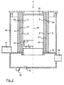
- FIG. 1 The drawing shows an oil mist separator 1 in a first embodiment in a vertical longitudinal section.
- the oil mist separator 1 comprises a housing 10 having a raw gas inlet 11 for crankcase ventilation gas coming from a crankcase of an associated internal combustion engine, a clean gas outlet 12 for de-oiled crankcase ventilation gas, and an oil collection area 13 located at the bottom of the housing 10 with an oil drain 14 for oil separated from the crankcase ventilation gas.
- a hollow cylindrical Diffusionsabscheide endeavor 2 is arranged, which has in its upper region a plurality of distributed over its circumference arranged through the gas channels 20.
- the diffusion separation body 2 is made of a fiber material or foam material or sintered material which is permeable to the crankcase ventilation gas and precipitates the oil mist entrained in the crankcase ventilation gas in the form of fine oil particles from the gas flow by diffusion deposition.
- a further diffusion separation body 2 ' is arranged at a distance from the diffusion separation body 2, which also has a hollow cylindrical shape, but has a lower height than the first diffusion separation body 2.
- Both diffusion separation bodies 2 and 2' are concentric to each other and to a central axis 19 of the oil mist separator 1 arranged.
- Diffusionsabscheide beneficia 2 and 2 ' connected to a housing 10 on the top closing lid 15, for example, glued or welded.
- an annular gap 21 is kept free.
- the outer, higher diffusion separation body 2 is with its lower end face on a base plate 16 and is also connected to this, preferably glued or welded.
- the radially inner diffusion separator body 2 'terminates at a downward distance from the base plate 16.
- the base plate 16 is pierced at its center to provide a flow path for the deoiled crankcase ventilation gas to the clean gas outlet 12.
- the diffusion separation bodies 2 and 2 ' are not yet loaded with oil and other substances entrained in the crankcase ventilation gas, so that they provide a low flow resistance for the crankcase ventilation gas.
- the crankcase ventilation gas flows in a predominant proportion and at low speed through the diffusion separation bodies 2 and 2 ', whereby the entrained oil is separated from the gas by diffusion deposition.
- the partial flow of the gas, which flows through the gas channels 20, then flows through the second diffusion separation body 2 ', whereby this gas partial stream is effectively de-oiled by diffusion deposition.
- the separated oil flows downward under gravity and passes through the perforated base plate 16 into the oil collection region 13, from where it is preferably returned to the crankcase of the associated internal combustion engine by the oil drain 14.
- the diffusion separation body 2 and 2 ' in each state the diffusion separation body 2 and 2 'has an effective oil mist separation, whereby first the oil mist separation takes place by deposition of the oil within the diffusion separation bodies 2 and 2' by diffusion deposition; With increasing loading of the diffusion separation body 2 and 2 ', the gas flow through the gas channels 20 increases, wherein an oil separation by impingement occurs in the surface regions 3. This is an effective oil mist separation and sufficient crankcase ventilation ensures over a very long period of operation, which avoids interference and damage to the associated internal combustion engine.
- crankcase ventilation gas flows substantially radially from outside to inside through the diffusion separation bodies 2 and 2' and then from the interior of the inner diffusion separation body 2 'axially down through the perforated base plate 16 to the clean gas outlet 12.
- the cross section and the number of gas channels 20 are selected such that that even at maximum laden Diffusionsabscheide redesignn 2 and 2 'still a sufficient derivative of crankcase ventilation gas is guaranteed and a maximum allowable pressure drop across the oil mist separator 1 is not exceeded.
- the gas channels 20 are self-cleaning due to the relatively high gas velocities occurring therein, so that there is no danger of blockage of the gas channels 20 even after a long period of operation.
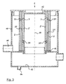
- FIG. 2 shows further embodiments of the oil mist separator 1, wherein in the left and in the right half of FIG. 2 two different versions are shown.
- the housing 10 with the Rohgaseinlass 11, the clean gas outlet 12, the oil collection area 13 and the oil discharge 14 and the lid 15 corresponds to the example according to FIG. 1 ,
- both diffusion separation bodies 2 and 2' together with their lower end face stand on the base plate 16.
- the radially outer diffusion separation body 2 is in the example according to Figure 2 with the example according to FIG. 1 match.
- the radially inner separation body 2 ' has in its lower region, that is, with a relatively large axial offset from the gas channels 20 located at the top in the outer diffusion separation body 2, one or more gas passages 30 in the form of relatively large openings.
- the gas passages 30 allow a low-resistance gas flow, so that the flow resistance of the oil mist separator 1 is kept advantageously low overall, even if the Diffusionsabscheide beneficia 2 and 2 'are heavily loaded.
- a further impact separation surface 4 ' may be provided radially inward of the gas passage 30.
- the impact separation surface 4 ' has a radially outer surface 3' of an annular, hollow cylindrical baffle plate as a deposition effective area, which is here in the circumferential direction into a plurality of sections, in particular per gas passage 30 a section divided.
- About radially resilient, axially extending connecting webs are the portions of the baffle plate 4 'is connected to the base plate 16 to hold it in the position shown and at the same time to allow a resilient movement in the radial direction.
- the impact separation surface 4 'initially abuts radially inward on the inner diffusion separation body 2' and then covers the gas passage 30.
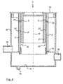
- FIG. 3 shows an embodiment of the oil mist separator 1, which in many parts with the in the FIG. 2 in the right half of the embodiment shown matches. It is different that in the example of the oil mist separator 1 after FIG. 3 the gas passages 30 are formed by inclined channels, wherein the channels 30 are designed to run obliquely downward in the radial direction from the outside inwards. As a result, in the region of the gas passages 30, sharp flow deflections which would lead to an increase in the flow resistance are avoided. Otherwise corresponds to the embodiment of the oil mist separator 1 according to FIG. 3 the examples described above.
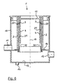
- FIG. 4 shows an embodiment of the oil mist separator 1, which in many parts the embodiment of the oil mist separator 1 according to FIG. 1 equivalent.
- the base plate 16 is designed differently.
- the base plate has a maximum large central opening, whereby a particularly large flow cross-section is provided for the deoiled crankcase ventilation gas flowing out of the inner region of the inner diffusion separator body 2 'and out of the annular gap 21 on the way to the clean gas outlet 12.
- FIG. 5 shows an example of the oil mist separator 1, in which the Diffusionsabscheide beneficia 2 and 2 'are made flat and plate-shaped.
- the two diffusion separation bodies 2 and 2 ' are likewise arranged here in a housing 10 into which the crankcase ventilation gas to be de-oiled is introduced via the raw gas inlet 11.
- the oil separation is wholly or largely predominantly within the Diffusionsabscheide endeavor 2 and 2' by diffusion deposition.
- an increasingly larger partial flow of the crankcase ventilation gas also flows through the gas channels 20 provided in the upper region of the first diffusion separation body 2.
- the gas channels 20 are in accordance with the present example FIG. 5 arranged perpendicular to the plane of the drawing one behind the other, whereby FIG. 5 only a single gas channel 20 is visible.
- crankcase ventilation gas stream flowing through the gas passages 20 strikes the surface 3, which is formed here by the surface of the second diffusion separation body 2 'facing the first diffusion separation body 2.
- the crankcase ventilation gas then flows partly through the second diffusion separation body 2 'according to FIG FIG. 5 to the right and partly through the gap 21 'between the Diffusionsabscheide benefician 2 and 2 'down and then through the at least one gas passage 30 in the second Diffusionsabscheide redesign 2' also to the right, from where the now de-oiled crankcase ventilation gas can flow through the total clean gas outlet 12.
- a lower portion of the housing 1 also forms an oil collection area 13, from where the separated oil can be removed by the oil discharge 14.
- Diffusionsabscheide endeavor 2 For holding and positioning the two flat, plate-shaped Diffusionsabscheide endeavor 2, 2 ' also serves a base plate 16, on which the two Diffusionsabscheide endeavor 2 and 2' are with their lower edge or lower edge. Further positioning takes place through the cover 15, which is connected on its underside to the upper edge of the two diffusion separation bodies 2 and 2 '.
- the Diffusionsabscheide endeavor 2 and 2 'thus together with the lid 15 also form an interconnected unit, which allows a simple replacement of Diffusionsabscheide redesign 2 and 2' in the context of maintenance.
- the exemplary embodiment of the oil mist separator 1 shown has only a single diffusion separation body 2.
- This diffusion separation body 2 is here again, similar to the examples according to FIGS FIGS. 1 to 4 , designed as a hollow cylinder.
- a hollow-cylindrical impact separation surface 4 Radially inwardly from the diffusion separation body 2 there is likewise arranged a hollow-cylindrical impact separation surface 4 with a radially outer, deposit-effective surface 3, which, like the diffusion separation body 2, extends concentrically to the central axis 19 of the oil mist separator 1.
- the hollow-cylindrical impact separation surface 4 is designed here in one piece with the lid 15 of the housing 10 for reasons of simple production.
- crankcase ventilation gas flows completely or largely predominantly through the diffusion separation body 2, whereby the entrained oil particles within the diffusion separation body 2 are deposited by diffusion deposition.
- crankcase ventilation gas With increasing loading of the diffusion separation body 2, an increasingly larger proportion of the crankcase ventilation gas also flows through the gas passages 20, which also run through the latter in the radial direction in the upper region of the diffusion separation body 2.
- the radially outer surface 3 of the Prallabscheide simulation 4 now forms the surface on which the flowing through the gas channels 20 partial flows of the crankcase ventilation gas, whereby an impact separation of entrained oil particles from the gas flow is effected.
- Severed oil flows here under gravity into the trained below in the housing 10 oil collection area 13, from where again an oil discharge 14 dissipates the collected oil.
- the diffusion separation body 2 is also connected at its upper front end to the underside of the lid 15 here.
- the lower end of the DiffusionsabscheideSchs 2 is connected to the base plate 16, whereby the Diffusionsabscheidelik 2, the lid 15 with the baffle plate 4 and the base plate 16 form an exchangeable unit.
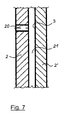
- FIG. 7 shows in enlarged scale a detail of one of the oil mist separator according to the FIGS. 1 to 5 ,
- the detail shows according to FIG. 7 a detail of the two Diffusionsabscheide redesignn 2 and 2 'with a running through the Diffusionsabscheide endeavor 2 gas channel 20.
- the gas channel 20 formed directly in the Diffusionsabscheide redesign 2, for example, by melting or welding or drilling or punching.
- a solidified surface of the gas channels 20 is advantageously obtained when the gas channels 20 melt, which gives them good dimensional stability without special measures.
- FIG. 8 shows in the same representation as the FIG. 7 a modified version.
- the difference to FIG. 7 is that in the example after FIG. 8 in the annular gap 21 between the two Diffusionsabscheide redesignn 2 and 2 ', a support body 5 is arranged.
- This support body 5 is expediently formed by a three-dimensional grid which keeps the annular gap 21 open and avoids deformation of the diffusion separation body 2 and 2 'during operation.
- the spatial structure of the support body 5 is of course designed so that a possible low-resistance flow through the crankcase ventilation gas along the annular gap 21 remains possible.
- the support body 5 may have a flow-guiding function and / or oil-separating function by a corresponding shape and structure.
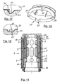
- FIG. 9 shows again in the same representation as the FIGS. 7 and 8th another embodiment.
- the gas channels 20 are formed here by sleeves 22 inserted into the first diffusion separation body 2.
- the gas channels 20 receive a permanently resistant contour, which can also be produced with high accuracy.
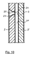
- FIG. 10 shows in the same representation as the FIGS. 7 to 9 an example in which the gas channels 20 upstream, that is in FIG. 10 on the left, are formed with an inflow funnel 23. Relative to that forms in the gas flow direction subsequent, ie in FIG. 10 right part of the gas channel 20 a constriction 24, whereby the gas channel 20 acts like a nozzle.
- FIG. 11 shows a modification of the embodiment according to FIG. 1 , where in the left half of FIG. 11 a Prallabscheide Chemistry 4 held in a resilient bearing 40 with a gas channel 20 facing surface 3 is shown.
- the surface 3 is under the action of a spring of the bearing 40 on the radially inner side of the DiffusionsabscheideSchs 2 and covers the gas channel 20.
- the entire gas flow now forcibly flows through the Diffusionsabscheide endeavor 2 and at least a partial flow of the gas subsequently the inner, further diffusion separation body 2 '.
- the impact separation surface 4 as a leaf valve made of a flexible metal plate or nonwoven platelets or elastomer platelets, each loaded in the closing direction with a spring or equipped with an inherent restoring force. Shown is the leaf valve in its open position.
- the deposition-effective surface 3 here is the surface of the platelet facing the diffusion deposition body 2.
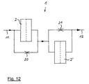
- FIG. 12 is a schematic diagram of the oil mist separator 1 according to FIG. 1 shown.
- On the left is the raw gas inlet 11, through which crankcase ventilation gas laden with oil mist is supplied.
- the gas stream flows through the diffusion separation body 2 and the free gas channels 20 in parallel, the latter acting as a throttle.
- the ratio of the partial flows adjusts according to the ratio of the flow resistances between the separation body 2 and the free gas channels 20.
- a fresh, unloaded separation body 2 by far the greater part of the gas flows through the separation body 2; With increasing loading of the separation body 2, an increasing part of the gas flows through the free gas channels 20, so that a gas flow is always ensured.
- crankcase ventilation gas stream Downstream of the second separation body 2' and the annular gap 21, the crankcase ventilation gas stream is reunited and now gets de-oiled in the clean gas outlet 12 also at strong or maximum laden AbscheideEff 2 and 2 'remains a sufficiently large flow cross-section through the gas channels 20 and the annular gap 21, so that always a sufficient crankcase ventilation is guaranteed. An impermissibly high pressure in the crankcase is thus reliably avoided.
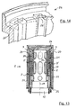
- FIG. 13 shows an example of a ⁇ lnebelabscheiders 1, which again has two concentrically arranged, hollow cylindrical Diffusionsabscheide endeavor 2 and 2 '.
- the separation bodies 2 and 2 ' are each formed by a fiber body 25, wherein the fiber bodies 25 are supported by a support body 26, which is designed here in several parts.
- the raw gas flows from radially outward and flows through first the outer diffusion separation body 2 and then the inner diffusion separation body 2 '.
- the free gas channels 20 are here in a transition region from the upper end face of the outer Abscheide stresses 2 to one of these facing side of the upper part of the support body 26 is formed.
- FIG. 14 shows in an enlarged section of the upper part of the support body 26 whose design.
- open grooves 26 'are formed which are bounded in the circumferential direction and upwards by the material of the support body 26 and which are initially open axially downwards.
- FIG. 15 also shows in a longitudinal section a further embodiment of the oil mist separator 1, which in other parts with the oil mist separator 1 according to FIG. 13 matches. The way is different, as in the oil mist separator 1 according to FIG. 15 the free gas channels 20 are formed.
- the support body 26 is formed in several parts with an upper, initially separate support member 27 which is connected to the rest of the support body 26, here latched, is.
- the support body part 27 has at its upper end face of the fiber body 25 of the outer Diffusionsabscheide endeavor 2 side facing in the circumferential direction distributed in the axial direction downwardly projecting lugs 27 'or lugs or the like suitable projections. These lugs 27 ensure that when attaching the support member 27, the material of the fiber body 25 is partially compressed in the axial direction. Since the cleats 27 'according to FIG. 16 On one side very steep, ie executed with an approximately perpendicular to the end face of the support member 27 extending slope, the material of the fiber body 25 of this slope can not follow, whereby the desired free gas channels 20 are formed.
- FIG. 17 shown in an enlarged detail.
- Top in the FIG. 17 is a section of the support member 27 can be seen, from which one of the lugs 27 'protrudes downward.
- FIG. 18 shows a modification of the support member 27 from FIG. 16 .
- FIG. 18 are pairs of two studs 27 'are provided instead of individual studs 27', which are mirror-symmetrical to each other, the steep flanks of the studs 27 'facing each other. In this way, approximately rectangular or square gas passages 20 are each cleared in the cross section when attaching the support member 27 on the rest of the support body 26 and kept free.
Landscapes
- Engineering & Computer Science (AREA)
- Chemical & Material Sciences (AREA)
- Chemical Kinetics & Catalysis (AREA)
- Mechanical Engineering (AREA)
- General Engineering & Computer Science (AREA)
- Lubrication Details And Ventilation Of Internal Combustion Engines (AREA)
Description
Die Erfindung betrifft einen Ölnebelabscheider einer Brennkraftmaschine, mit mindestens einem von dem Kurbelgehäuseentlüftungsgas der Brennkraftmaschine durchströmbaren gasdurchlässigen Diffusionsabscheidekörper, in welchem in dem Kurbelgehäuseentlüftungsgas enthaltener Ölnebel aus dem Gas abscheidbar ist. Die
Dieses bekannte Kurbelgehäuseventilationssystem erfordert ersichtlich einen hohen technischen Aufwand, weil es neben dem Koaleszerfilter zwei Ventile umfasst, die den Herstellungsaufwand deutlich erhöhen. Ein weiterer Nachteil wird bei diesem bekannten Ventilationssystem darin gesehen, dass in einem verstopften Zustand des Koaleszerfilters, bei dem das Umgehungsventil öffnet, die Leckgase nicht mehr oder nur noch in einem geringen Umfang von den mitgerissenen Ölpartikeln gereinigt werden oder sogar ungereinigt in die Umwelt entlassen werden.This known Kurbelgehäusententilationssystem obviously requires a high technical effort, because it includes in addition to the Koaleszer filter two valves that significantly increase the production cost. Another disadvantage is seen in this known ventilation system is that in a clogged state of the coalescer, in which the bypass valve opens, the leak gases are no longer or only to a small extent cleaned by the entrained oil particles or discharged unpurified into the environment ,
Die
Bei diesem Abscheider handelt es sich also kurz gesagt um eine Reihenschaltung eines Prallabscheiders und eines Durchströmungsfilters, wobei die Gas-Flüssigkeits-Strömung zunächst den Prallabscheider und danach das Durchströmungsfilter durchläuft. Zwar wird im Betrieb dieses Abscheiders der größte Teil der Ölpartikel schon im Prallabscheider abgeschieden, es gelangt jedoch immer noch ein gewisser Anteil an Ölpartikeln in das Durchströmungsfilter, wodurch sich im Laufe der Betriebszeit des Abscheiders der Durchflusswiderstand des Durchströmungsfilters durch darin dauerhaft verbleibende Ablagerungen erhöht, bis schließlich das Durchströmungsfilter vollständig verstopft ist. In diesem Zustand ist dann keine weitere Funktion des Abscheiders mehr möglich und es kommt zu Fehlfunktionen des zugehörigen Motors, sofern nicht rechtzeitig im Rahmen von Wartungsmaßnahmen das Durchströmungsfilter gereinigt oder ersetzt wird.Briefly, this separator is therefore a series connection of an impact separator and a flow-through filter, the gas-liquid flow first passing through the impact separator and then through the flow-through filter. Although in the operation of this separator most of the Oil particles are already deposited in the impact separator, but still a certain amount of oil particles in the flow filter, which increases the flow resistance of the flow filter through it permanently remaining deposits during the operating time of the separator until finally the flow filter is completely clogged. In this state, no further function of the separator is then possible and it comes to malfunction of the associated engine, unless timely in the context of maintenance measures, the flow filter is cleaned or replaced.
Die
Bei diesem bekannten Abscheider wird als nachteilig angesehen, dass er mit dem Aktuator ein bewegliches, gezielt zu verstellendes Element umfasst, das im Betrieb des Abscheiders einem Verschleiß unterliegt und das die Herstellung des Abscheiders aufwendig macht. Zudem besteht bei beweglichen Teilen in einem Ölnebelabscheider immer die Gefahr einer Funktionsstörung beweglicher Teile dadurch, dass die im Kurbelgehäuseentlüftungsgas mitgeführten Ölpartikel und sonstigen Bestandteile eine klebrige Konsistenz aufweisen, die die Beweglichkeit des Aktuators und der damit verbundenen Teile mit zunehmender Betriebszeit des Abscheiders erschwert oder schließlich ganz verhindert.In this known separator is considered to be disadvantageous that it comprises a movable, specifically to be adjusted element with the actuator, which is subject to wear during operation of the separator and makes the preparation of the separator consuming. In addition, there is always the risk of malfunction of moving parts in moving parts in a Ölnebelabscheider characterized in that the entrained in the crankcase ventilation gas oil particles and other ingredients have a sticky consistency that complicates the mobility of the actuator and the associated parts with increasing operating time of the separator or finally completely prevented.
Aus der
Bei dieser Vorrichtung handelt es sich um einen reinen Prallabscheider, der einen guten Wirkungsgrad für relativ große Ölpartikel, die das Kurbelgehäuseentlüftungsgas enthält, bietet. Gerade bei modernen Brennkraftmaschinen tritt aber in zunehmendem Maße ein feinerer Ölnebel auf, der aus kleinen Ölpartikeln besteht, die in einem reinen Prallabscheider durch vorrangig Massenträgheitskräfte nur noch mit vermindertem Wirkungsgrad abgeschieden werden können. Dadurch kommt es zu einer unvollständigen Entölung des Kurbelgehäuseentlüftungsgases und zu einem Durchtritt von Ölanteilen durch den Abscheider hindurch, was zu Störungen an der Brennkraftmaschine führen kann, beispielsweise weil in einem die Gase aus dem Abscheider aufnehmenden Ansaugtrakt der Brennkraftmaschine liegende Komponenten durch Öl verschmutzt werden, wie Drosselklappengelenke oder Luftmengenmesser. Zudem ist die Wahl der Anordnung dieses Abscheiders dadurch eingeschränkt, dass er an einer heißen Stelle, also nahe an im Betrieb heißen Teilen der zugehörigen Brennkraftmaschine, angeordnet werden muss.This device is a pure baffle trap that provides good efficiency for relatively large oil particles containing the crankcase breather gas. Especially in modern internal combustion engines but increasingly occurs to a finer oil mist, which consists of small oil particles that can be deposited in a pure impact separator by primarily inertia forces only with reduced efficiency. This results in an incomplete Entölung the crankcase ventilation gas and a passage of oil components through the separator through, which can lead to malfunctions of the internal combustion engine, for example, because in a the gases from the separator receiving intake tract of the internal combustion engine components are contaminated by oil, such as Throttle joints or air flow meter. In addition, the choice of the arrangement of this separator is limited by the fact that it must be located at a hot spot, so close to hot in operation parts of the associated internal combustion engine.
Für die vorliegende Erfindung stellt sich deshalb die Aufgabe, einen Ölnebelabscheider der eingangs genannten Art zu schaffen, der die vorstehend dargelegten Nachteile vermeidet und der bei einem einfachen Aufbau und kostengünstiger Herstellbarkeit einen hohen Abscheidewirkungsgrad, auch für feine Ölpartikel, sowie eine lange wartungsfreie Einsatzzeit aufweist und der dabei jederzeit einen unzulässig hohen Druck im Kurbelgehäuse der zugehörigen Brennkraftmaschine vermeidet.Therefore, for the present invention, the object is to provide an oil mist separator of the type mentioned above, the above-stated Disadvantages avoids and with a simple structure and cost manufacturability has a high Abscheidewirkungsgrad, even for fine oil particles, as well as a long maintenance-free operation time and it always avoids an unacceptably high pressure in the crankcase of the associated internal combustion engine.
Die Lösung dieser Aufgabe gelingt erfindungsgemäß mit einem Ölnebelabscheider der eingangs genannten Art, der dadurch gekennzeichnet ist, dass in dem/jedem Diffusionsabscheidekörper zusätzlich durchgehende freie Gaskanäle ausgebildet sind und dass in Strömungsrichtung des Kurbelgehäuseentlüftungsgases gesehen hinter den Gaskanälen mit Abstand zu dem/jedem Diffusionsabscheidekörper wenigstens ein weiterer Diffusionsabscheidekörper oder eine Prallabscheidefläche angeordnet ist.The solution of this object is achieved according to the invention with a Ölnebelabscheider of the type mentioned, which is characterized in that in the / each Diffusionsabscheidekörper additionally continuous free gas channels are formed and seen in the flow direction of the crankcase ventilation gas behind the gas ducts at a distance from the / each Diffusionsabscheidekörper at least one further diffusion separator or a Prallabscheidefläche is arranged.
Der erfindungsgemäße Ölnebelabscheider bietet vorteilhaft bei einem sehr einfachen konstruktiven Aufbau über eine sehr lange Einsatzzeit einen sehr hohen Anteil an sehr wirksamer Diffusionsabscheidung. Dabei erfolgt das Abscheiden des Ölnebels je nach Zustand des Diffusionsabscheidekörpers in unterschiedlichen Verhältnissen zwischen den beiden Abscheidemechanismen. In einem frischen Zustand des Diffusionsabscheidekörpers hat dieser eine sehr hohe Durchlässigkeit, so dass der größte Teil des Volumenstroms des Kurbelgehäuseentlüftungsgases den oder die Diffusionsabscheidekörper durchströmt, wodurch im Kurbelgehäuseentlüftungsgas mitgeführter Ölnebel in Form von Ölpartikeln innerhalb des Diffusionsabscheidekörpers überwiegend durch Diffusionsabscheidung abgeschieden wird. Die Gasgeschwindigkeit ist dabei überall, auch in den freien Gaskanälen, sehr gering, wodurch auch feinste Partikel durch Diffusionsabscheidung effektiv abgeschieden werden; diese Effektivität ist mit einem reinen Prallabscheider nicht möglich. Dabei spielt der Teilvolumenstrom des Kurbelgehäuseentlüftungsgases, der durch die freien Gaskanäle strömt, anteilmäßig nur eine geringe Rolle, weil dieser Teilvolumenstrom bei geringem Strömungswiderstand des Diffusionsabscheidekörpers sehr klein ist. Bei sich im Laufe der Einsatzzeit des Ölnebelabscheiders zunehmend zusetzendem Diffusionsabscheidekörper, also bei einem zunehmenden Durchflusswiderstand des Diffusionsabscheidekörpers, steigt der Teilvolumenstrom des Kurbelgehäuseentlüftungsgases, der durch die freien Gaskanäle strömt, an. Aus diesem Teilvolumenstrom des Kurbelgehäuseentlüftungsgases erfolgt eine Ölnebelabscheidung entweder durch den weiteren, dann noch geringer beladenen Diffusionsabscheidekörper oder durch die Prallabscheidung an der Prallabscheidefläche. In der Ausführung mit zwei Diffusionsabscheidekörpern durchströmt das Kurbelgehäuseentlüftungsgas hier bei einem frischen Zustand der Diffusionsabscheidekörper zwei in Reihe geschaltete Diffusionsabscheidekörper, wodurch ein besonders hoher Abscheidewirkungsgrad durch Diffusionsabscheidung erreicht wird. Der Gasteilstrom, der durch die freien Gaskanäle des ersten Diffusionsabscheidekörpers strömt, fließt bei frischen Diffusionsabscheidekörpern anschließend durch den weiteren Diffusionsabscheidekörper hindurch, sodass auch dieser Gasteilstrom durch Diffusionsabscheidung entölt wird. Bei zunehmend beladenen Diffusionsabscheidekörpern strömt das Gas zunehmend durch die freien Gaskanäle, was die Kurbelgehäuseentlüftung gewährleistet. Eine Entölung des Kurbelgehäuseentlüftungsgases erfolgt dann immerhin noch durch Prallabscheidung. Somit behält der Ölnebelabscheider über lange Einsatzzeiten einen hohen Abscheidewirkungsgrad durch Diffusionsabscheidewirkung und ein zu hoher Druckabfall über dem Ölnebelabscheider, der zu einem zu hohen Druck im Kurbelgehäuse der zugehörigen Brennkraftmaschine führen könnte, wird auch nach langer Betriebszeit und bei zunehmend beladenem Diffusionsabscheidekörper oder -körpern vermieden. Da die Diffusionsabscheidekörper Abstand voneinander aufweisen oder die Prallabscheidefläche jeweils Abstand von dem in Strömungsrichtung davor liegenden Diffusionsabscheidekörper mit den Gaskanälen aufweist, wird jeweils ein Spaltraum frei gehalten, der für die Führung des Kurbelgehäuseentlüftungsgases genutzt wird. Somit sind vorteilhaft auch keine besonderen Anordnungen für die Ausbildung von Gasströmungswegen erforderlich. Aufgrund des Fehlens jeglicher beweglicher Elemente in dem vorstehend beschriebenen Ölnebelabscheider ist dieser kostengünstig herstellbar und zuverlässig in seiner Funktion.The oil mist separator according to the invention advantageously offers a very high proportion of very effective diffusion separation over a very long service life, with a very simple structural design. In this case, the deposition of the oil mist takes place depending on the state of Diffusionsabscheidekörpers in different ratios between the two deposition mechanisms. In a fresh state of the Diffusionsabscheidekörpers this has a very high permeability, so that the majority of the volume flow of the crankcase ventilation gas flows through the diffusion or the diffusion, whereby entrained in the crankcase ventilation gas entrained oil mist in the form of oil particles within the diffusion separation body mainly by diffusion deposition. The gas velocity is everywhere, even in the free gas channels, very low, so that even the finest particles are effectively deposited by diffusion deposition; this effectiveness is not possible with a pure impact separator. In this case, the partial volume flow of the crankcase ventilation gas, which flows through the free gas channels, proportionately only a small role, because this partial flow is very small at low flow resistance of Diffusionsabscheidekörpers. In the course of the time of use of the oil mist separator increasingly zusetzendem diffusion separation, so with an increasing flow resistance of Diffusionsabscheidekörpers, the partial volume flow of the crankcase ventilation gas flowing through the free gas channels, increases. For this partial volume flow of the crankcase ventilation gas, an oil mist separation takes place either by the further, then even less loaded diffusion separation body or by the impact separation at the impact separation surface. In the Execution with two Diffusionabscheidekörpern the crankcase ventilation gas flows through here in a fresh state of Diffusionsabscheidekörpers two series-connected Diffusionabscheidekörper, whereby a particularly high separation efficiency is achieved by diffusion deposition. The partial gas flow, which flows through the free gas channels of the first diffusion separation body, then flows through the further diffusion separation body in the case of fresh diffusion separation bodies, so that this partial gas flow is also depleted by diffusion deposition. With increasingly loaded diffusion separation bodies, the gas flows increasingly through the free gas channels, which ensures the crankcase ventilation. A de-oiling of the crankcase ventilation gas then still takes place by impact separation. Thus, the Ölnebelabscheider over long periods of use maintains a high separation efficiency by Diffusionsabscheidewirkung and too high a pressure drop across the oil mist separator, which could lead to excessive pressure in the crankcase of the associated internal combustion engine is avoided even after long periods of operation and increasingly loaded Diffusionsabscheidekörper or bodies. Since the diffusion separation bodies are at a distance from one another or the impact separation surface is at a distance from the diffusion separation body in the flow direction with the gas channels, a gap space is kept free which is used to guide the crankcase ventilation gas. Thus, advantageously no special arrangements for the formation of gas flow paths are required. Due to the absence of any movable elements in the oil mist separator described above, this is inexpensive to produce and reliable in its function.
Bevorzugt ist weiter vorgesehen, dass die Gaskanäle senkrecht zu einer Flächenebene des Diffusionsabscheidekörpers verlaufen und dass der weitere Diffusionsabscheidekörper oder die Prallabscheidefläche parallel zur Flächenebene des Diffusionsabscheidekörpers verläuft. In dieser Ausgestaltung ist eine besonders platzsparende Bauweise des Ölnebelabscheiders möglich.Preferably, it is further provided that the gas channels extend perpendicular to a surface plane of the diffusion separation body and that the further diffusion separation body or the impact separation surface extends parallel to the surface plane of the diffusion separation body. In this embodiment, a particularly space-saving design of Ölnebelabscheiders is possible.
Ein weiterer Beitrag zum Niedrighalten des Strömungswiderstandes des Ölnebelabscheiders besteht darin, dass der weitere Diffusionsabscheidekörper oder die Prallabscheidefläche zu den Gaskanälen des Diffusionsabscheidekörpers versetzt wenigstens einen Gasdurchlass aufweist. Der Gasdurchlass hat dabei zweckmäßig einen Strömungsquerschnitt, der größer ist als der Strömungsquerschnitt der Gaskanäle. Hierdurch wird der Druckabfall über den Ölnebelabscheider niedrig gehalten, was für den Betrieb wesentlich ist, da an Brennkraftmaschinen häufig nur eine geringe Druckdifferenz zum Betreiben des Ölnebelabscheiders zur Verfügung steht.Another contribution to keeping the flow resistance of the oil mist separator low is that the further diffusion separation body or the impact separation surface offset from the gas channels of the diffusion separation body has at least one gas passage. The gas passage expediently has a flow cross section which is greater than the flow cross section of the gas passages. As a result, the pressure drop over the oil mist separator is kept low, which is essential for the operation, since often only a small pressure difference is available for operating the oil mist separator on internal combustion engines.
Eine weitere Ausgestaltung des Ölnebelabscheiders schlägt vor, dass in Strömungsrichtung des Kurbelgehäuseentlüftungsgases gesehen hinter dem Gasdurchlass mit Abstand zu diesem wenigstens ein weiterer Diffusionsabscheidekörper oder eine weitere Prallabscheidefläche angeordnet ist. In dieser Ausführung des Ölnebelabscheiders wird der Gasstrom durch den Ölnebelabscheider einer zweifachen Prallabscheidung unterzogen, wenn der Diffusionsabscheidekörper zunehmend beladen wird. Solange der Abscheidekörper noch gut durchlässig ist, wird die Abscheidung im Diffusionsabscheidekörper vorgenommen. Insgesamt ist in jedem Betriebszustand des Ölnebelabscheiders und des darin angeordneten Diffusionsabscheidekörpers ein hoher Abscheidewirkungsgrad gewährleistet.A further embodiment of the oil mist separator suggests that, viewed in the flow direction of the crankcase ventilation gas, at least one further diffusion separation body or a further impact separation area is arranged behind the gas passage at a distance therefrom. In this embodiment of the oil mist separator, the gas flow through the oil mist separator is subjected to double impact deposition as the diffusion separation body becomes increasingly laden. As long as the separation body is still well permeable, the deposition is carried out in Diffusionsabscheidekörper. Overall, a high degree of separation efficiency is ensured in each operating state of the oil mist separator and the diffusion separation body arranged therein.
Weiter ist vorgesehen, dass die Prallabscheidefläche oder mindestens eine der Prallabscheideflächen durch eine geschlossene, gas- und öldichte Prallplatte gebildet ist. In dieser Ausführung kann die Prallabscheidefläche besonders einfach hergestellt und in den Ölnebelabscheider integriert werden.It is further provided that the impact separation surface or at least one of the impact separation surfaces is formed by a closed, gas and oil-tight baffle plate. In this embodiment, the impact separation surface can be particularly easily manufactured and integrated into the oil mist separator.
Um den Ölnebelabscheider besonders kompakt gestalten zu können, wird vorgeschlagen, dass der oder die Diffusionsabscheidekörper und die Prallabscheidefläche oder -flächen jeweils eine hohlzylindrische Form haben und konzentrisch zueinander um eine Mittelachse angeordnet sind. In dieser Ausführung wird bei einem geringen Bauvolumen des Ölnebelabscheiders eine große Fläche für den oder die Diffusionsabscheidekörper zur Verfügung gestellt, was eine gute Ölnebelabscheidung bei geringem Strömungswiderstand bietet.In order to make the oil mist separator particularly compact, it is proposed that the one or more Diffusionsabscheidekörper and the Aballabscheidefläche or surfaces each have a hollow cylindrical shape and are arranged concentrically to each other about a central axis. In this embodiment, with a small volume of construction of the oil mist separator, a large area is provided for the diffusion separation body or bodies, which offers good oil mist separation with low flow resistance.
Ein dazu alternativer Vorschlag sieht vor, dass der Diffusionsabscheidekörper oder die Diffusionsabscheidekörper und die Prallabscheidefläche oder -flächen jeweils im Querschnitt gesehen spiralförmig angeordnet sind.An alternative proposal for this provides that the diffusion separation body or the diffusion separation body and the impact separation surface or surfaces are each arranged spirally in cross section.
Eine weitere Alternative sieht vor, dass der Diffusionsabscheidekörper oder die Diffusionsabscheidekörper und die Prallplatte oder die Prallplatten eine flache ebene Form haben und parallel zueinander angeordnet sind. In dieser Ausgestaltung kann der Ölnebelabscheider besonders flach gestaltet werden, was bei manchen Einbausituationen von Vorteil sein kann.Another alternative provides that the diffusion separation body or the diffusion separation body and the baffle plate or the baffle plates have a flat planar shape and are arranged parallel to each other. In this embodiment can the Ölnebelabscheider be designed particularly flat, which may be advantageous in some installation situations.
Damit im Betrieb des Ölnebelabscheiders keine unerwünschten Deformationen des Diffusionsabscheidekörpers oder der Diffusionsabscheidekörper auftreten, wird weiter vorgeschlagen, dass zwischen den Diffusionsabscheidekörpern oder zwischen dem Diffusionsabscheidekörper und der nachgeordneten Prallabscheidefläche wenigstens ein gas- und öldurchlässiger Stützkörper angeordnet ist. Dieser Stützkörper sorgt dafür, dass der/jeder Diffusionsabscheidekörper auch in einem beladenen Zustand, der den Druckabfall über den Diffusionsabscheidekörper erhöht, seine gewünschte, vorgegebene Form behält und dass Strömungswege in Strömungsrichtung hinter dem Diffusionsabscheidekörper zuverlässig offen gehalten werden.So that no undesirable deformations of the diffusion separation body or the diffusion separation body occur during operation of the oil mist separator, it is further proposed that at least one gas- and oil-permeable support body be arranged between the diffusion separation bodies or between the diffusion separation body and the downstream impact deposition surface. This supporting body ensures that the / each diffusion separation body, even in a loaded state which increases the pressure drop across the diffusion separation body, retains its desired, predetermined shape and that flow paths downstream of the diffusion separation body are reliably kept open.
Bevorzugt ist der Stützkörper durch ein dreidimensionales Gitter gebildet, da ein solches Gitter einerseits einfach und kostengünstig herstellbar ist und andererseits die gewünschte Wirkung zuverlässig erzielt.Preferably, the support body is formed by a three-dimensional grid, since such a grid on the one hand simple and inexpensive to produce and on the other hand, the desired effect achieved reliably.
Zusätzlich kann der Stützkörper eine Form und/oder Struktur haben, die für das den Stützkörper durchströmende Gas eine Gasleitfunktion und/oder für den in dem den Stützkörper durchströmenden Gas enthaltenen Ölnebel eine Abscheidefunktion hat.In addition, the support body may have a shape and / or structure which has a gas-conducting function for the gas flowing through the support body and / or a separating function for the oil mist contained in the gas flowing through the support body.
Der Diffusionsabscheidekörper kann Körper aus unterschiedlichen Materialien aufweisen. Wesentlich ist dabei, dass der Diffusionsabscheidekörper in der Lage ist, aus dem ihn durchströmenden Kurbelgehäuseentlüftungsgas die darin mitgeführten, insbesondere feinen Ölpartikel abzuscheiden und innerhalb des Diffusionsabscheidekörpers zu speichern und/oder innerhalb des Diffusionsabscheidekörpers einer Ölabführung zuzuleiten. Eine erste diesbezügliche bevorzugte Ausgestaltung sieht vor, dass der oder jeder Diffusionsabscheidekörper mindestens einen Faser- oder Schaumkörper aufweist.The diffusion separation body may comprise bodies of different materials. It is essential that the diffusion separation body is able to separate from the crankcase ventilation gas flowing through it the, in particular fine oil particles entrained therein and to store it within the diffusion separation body and / or to supply it to an oil removal within the diffusion separation body. A first related preferred embodiment provides that the or each Diffusionsabscheidekörper has at least one fiber or foam body.
Insbesondere zwecks einfacher Herstellbarkeit ist vorgesehen, dass ein den Faser- oder Schaumkörper bildendes Material in einem Ausgangszustand bahnförmig ist und eine geringere Dicke als der Faser- oder Schaumkörper aufweist und dass das bahnförmige Material zu dem Faser- oder Schaumkörper gewickelt ist. Dabei kann die Bahn beispielsweise unmittelbar auf den vorstehend erwähnten Stützkörper aufgewickelt sein. Alternativ besteht die Möglichkeit, zunächst die Bahn auf einem Hilfskörper zu dem Faser- oder Schaumkörper zu wickeln und dann nach Entfernen des Hilfskörpers den Stützkörper in den Faser- oder Schaumkörper einzusetzen.In particular, for ease of manufacture is provided that a fiber or foam body forming material is web-shaped in a starting state and has a smaller thickness than the fiber or foam body and that the sheet-like material is wound into the fiber or foam body. In this case, the web can for example be wound directly on the above-mentioned support body. Alternatively, it is possible to first the web on one To wrap auxiliary body to the fiber or foam body and then insert after removing the auxiliary body, the support body in the fiber or foam body.
Eine weitere herstellungstechnisch günstige Ausführung schlägt vor, dass ein den Faser- oder Schaumkörper bildendes Material in einem Ausgangszustand bahnförmig ist und eine der Dicke des Faser- oder Schaumkörper entsprechende Dicke aufweist und dass das bahnförmige Material zusammen mit dem in einem Ausgangszustand ebenfalls bahnförmigen Stützkörper in Spiralform zu dem Faser- oder Schaumkörper oder zu mehreren Faser- oder Schaumkörpern gewickelt ist. Dies ergibt einen Ölnebelabscheider, bei dem nicht separate Diffusionsabscheidekörper konzentrisch zueinander angeordnet sind, sonders es liegt eine Spiralform vor, die aber zu den gleichen funktionalen Eigenschaften des Ölnebelabscheiders führt. Die Zahl der übereinander gewickelten Lagen kann dabei zweckgemäß variiert werden. Zwischen den Windungen der Spirale wird ein Freiraum freigehalten, hier mittels des Stützkörpers.A further manufacturing technology favorable embodiment proposes that a fiber or foam body forming material in a starting state is web-shaped and one of the thickness of the fiber or foam body corresponding thickness and that the web-like material together with the in an initial state also web-shaped supporting body in a spiral shape to the fiber or foam body or to several fiber or foam bodies is wound. This results in a Ölnebelabscheider, in which not separate Diffusionsabscheidekörper are arranged concentrically to each other, in particular there is a spiral shape, but which leads to the same functional properties of the Ölnebelabscheiders. The number of superposed layers can be suitably varied. Between the turns of the spiral, a free space is kept free, here by means of the support body.
Eine weitere geeignete Formgestaltung besteht darin, dass der/jeder Faser- oder Schaumkörper die Form eines Hohlprofils, vorzugsweise eines Hohlzylinders, hat. Durch abgestufte Durchmesser können bei Bedarf mehrere Körper konzentrisch zueinander angeordnet werden.Another suitable shape design is that the / each fiber or foam body has the shape of a hollow profile, preferably a hollow cylinder. By graduated diameter, if necessary, several bodies can be arranged concentrically with each other.
Insbesondere für nicht aus sich selbst formbeständige Faser- oder Schaumkörper wird vorgeschlagen, dass der oder jeder Diffusionsabscheidekörper neben dem mindestens einen Faser- oder Schaumkörper einen den/die Faser- oder Schaumkörper tragenden Tragkörper aufweist.In particular for fiber or foam bodies which are not inherently dimensionally stable, it is proposed that the or each diffusion separation body has, in addition to the at least one fiber or foam body, a support body carrying the fiber or foam body.
In einer weiteren Ausgestaltung ist bevorzugt der oder jeder Faserkörper aus einem Filzmaterial aus thermo- oder duroplastischen Kunststofffasern oder Metallfasern oder Karbonfasern oder Glasfasern oder aus einem Papiermaterial hergestellt.In a further embodiment, the or each fiber body is preferably made of a felt material made of thermoplastic or thermosetting plastic fibers or metal fibers or carbon fibers or glass fibers or of a paper material.
Alternativ kann der Faserkörper aus einem Vlies oder Gewebe oder Gelege oder Gewirk oder Gestrick aus thermo- oder duroplastischen Kunststofffasern oder Metallfasern oder Karbonfasern oder Glasfasern hergestellt sein.Alternatively, the fibrous body may be made of a nonwoven or woven fabric or scrim or knit or knit of thermoplastic or thermoset plastic fibers or metal fibers or carbon fibers or glass fibers.
Bevorzugt ist der Schaumkörper aus einem Kunststoff- oder Metall- oder Glasschaum hergestellt.Preferably, the foam body is made of a plastic or metal or glass foam.
Zweckmäßig kann der Schaumkörper aus einem offenzelligen thermo- oder duroplastischen Schaumkunststoff hergestellt sein.Suitably, the foam body may be made of an open-cell thermosetting or thermosetting foam plastic.
Weiter besteht die Möglichkeit, dass der oder jeder Diffusionsabscheidekörper mindestens einen Sinterkörper aufweist.Furthermore, there is the possibility that the or each diffusion separation body has at least one sintered body.
Die oben erwähnten freien Gaskanäle im Diffusionsabscheidekörper können unterschiedlich ausgestaltet und erzeugt sein. Eine erste diesbezügliche Ausführung schlägt vor, dass die Gaskanäle unmittelbar in das Material des Faserkörpers oder Schaumkörpers oder Sinterkörpers eingeschmolzen oder eingeschweißt oder eingebohrt oder eingestanzt oder eingestochen oder eingeschnitten sind. In dieser Ausgestaltung ist eine besonders einfache Fertigung gewährleistet, da keine besonderen Bauteile für die Gaskanäle dauerhaft in dem Faserkörper oder Schaumkörper oder Sinterkörper angebracht werden müssen.The above-mentioned free gas channels in Diffusionsabscheidekörper can be designed differently and generated. A first related embodiment proposes that the gas channels are melted or welded or drilled or punched or punched or cut directly into the material of the fiber body or foam body or sintered body. In this embodiment, a particularly simple production is ensured because no special components for the gas channels must be permanently mounted in the fiber body or foam body or sintered body.
Alternativ können die Gaskanäle durch in das Material des Faserkörpers oder Schaumkörpers oder Sinterkörpers eingesteckte Hülsen gebildet sein. In dieser Ausführung ist zwar der Aufwand etwas höher, jedoch bieten die eingesteckten Hülsen den Vorteil, dass die Gaskanäle mit besonders exakten und dauerhaft beständigen Konturen hergestellt werden können. Zur Lagesicherung sind die Hülsen bei Bedarf in geeigneter Weise im Körper fixiert, z.B. durch Verkleben oder Verschweißen oder durch beidseitige Kragen.Alternatively, the gas channels may be formed by sleeves inserted in the material of the fiber body or foam body or sintered body. In this embodiment, although the effort is slightly higher, but the inserted sleeves offer the advantage that the gas channels can be made with particularly precise and durable resistant contours. To secure the position, the sleeves are suitably fixed in the body as needed, e.g. by gluing or welding or by double-sided collar.
Statt im Material des Faserkörpers oder Schaumkörpers oder Sinterkörpers können die Gaskanäle auch in einem Übergangsbereich zwischen mindestens einem Stirnende oder Rand des Faserkörpers oder Schaumkörpers oder Sinterkörpers und einem diesem benachbarten Bereich des zugehörigen Tragkörpers angeordnet sein. Hiermit ist insbesondere eine Formbeständigkeit der Gaskanäle einfacher zu erzielen.Instead of being in the material of the fiber body or foam body or sintered body, the gas passages can also be arranged in a transition region between at least one front end or edge of the fiber body or foam body or sintered body and an adjacent region of the associated support body. Hereby, in particular a dimensional stability of the gas channels is easier to achieve.
In einer Ausgestaltung ist vorgesehen, dass der Tragkörper an seiner dem Faserkörper oder Schaumkörper oder Sinterkörper zugewandten Seite zu diesem hin offene Nuten aufweist, die durch das Stirnende oder den Rand des Faserkörpers oder Schaumkörpers oder Sinterkörpers zu den Gaskanälen begrenzt sind. Hier wird die Fertigung besonders einfach.In one embodiment, it is provided that the support body has, at its side facing the fiber body or foam body or sintered body, grooves which are open towards the latter and are bounded by the front end or the edge of the fiber body or foam body or sintered body to the gas passages. Here the production becomes particularly easy.
In einer anderen Ausgestaltung ist vorgesehen, dass der Tragkörper zwei- oder mehrteilig ist und dass ein Tragkörperteil an seiner dem Stirnende oder Rand des Faserkörpers oder Schaumkörpers oder Sinterkörpers zugewandten Seite einen oder mehrere vorspringende Stollen oder Paare von Stollen besitzt, die im verbundenen Zustand der Tragkörperteile den Faserkörper oder Schaumkörper oder Sinterkörper randseitig partiell eindrücken und so die Gaskanäle bilden. Hier werden die Gaskanäle einfach durch das Verbinden der Tragkörperteile miteinander gebildet.In another embodiment, it is provided that the support body is two or more parts and that a support body part has on its front end or edge of the fiber body or foam body or sintered body side facing one or more projecting lugs or pairs of studs, in the connected state of the support body parts Partially press the fiber body or foam body or sintered body edge side and thus form the gas channels. Here, the gas channels are formed simply by connecting the carrier body parts together.
In einer besonders einfach herstellbaren Ausführung weisen die Gaskanäle über ihre gesamte Länge jeweils einen konstanten Querschnitt auf.In a particularly simple to manufacture embodiment, the gas channels each have a constant cross section over their entire length.
Bevorzugt haben dabei die Gaskanäle einen runden oder mehreckigen oder spaltartigen Querschnitt.Preferably, the gas channels have a round or polygonal or slit-like cross section.
Zur Erzielung günstiger Strömungsverhältnisse mit geringen Strömungswiderständen in den Gaskanälen können diese erfindungsgemäß eingangsseitig mit einem Einströmtrichter ausgebildet sein.To achieve favorable flow conditions with low flow resistance in the gas ducts, these invention can be formed on the input side with a Einströmtrichter.
Eine hohe Ausströmgeschwindigkeit des Kurbelgehäuseentlüftungsgases aus den Gaskanälen ist für die Prallabscheidung an der Prallabscheidefläche im Falle von stark beladenen Diffusionsabscheidekörpern günstig. Wenn eine besonders hohe Strömungsgeschwindigkeit erzielt werden soll, können erfindungsgemäß die Gaskanäle ausgangsseitig mit einer düsenartigen Verengung ausgebildet sein. Zudem hat eine hohe Gasgeschwindigkeit in den Gaskanälen den Vorteil, dass eine Selbstreinigungswirkung erzielt wird, so dass ein Zusetzen der Gaskanäle praktisch nicht auftreten kann.A high outflow velocity of the crankcase ventilation gas from the gas passages is favorable for impact deposition at the impact separation surface in the case of heavily loaded diffusion separation bodies. If a particularly high flow velocity is to be achieved, according to the invention the gas channels can be designed on the output side with a nozzle-like constriction. In addition, a high gas velocity in the gas channels has the advantage that a self-cleaning effect is achieved, so that clogging of the gas channels can practically not occur.
Zur Sicherstellung eines störungsfreien Betriebes der zugehörigen Brennkraftmaschine auch bei stark beladenem Diffusionsabscheidekörper ist zweckmäßig vorgesehen, dass der Ölnebelabscheider, insbesondere der addierte Strömungsquerschnitt aller Gaskanäle, so ausgelegt und bemessen ist, dass auch in einem stark oder maximal beladenen Zustand des Diffusionsabscheidekörpers oder der Diffusionsabscheidekörper ein maximal zulässiger Druckabfall über dem Ölnebelabscheider nicht überschritten wird.To ensure trouble-free operation of the associated internal combustion engine even with heavily loaded diffusion separator is expedient provided that the oil mist, in particular the added flow cross-section of all gas channels, is designed and dimensioned so that even in a heavily or maximally loaded state of Diffusionsabscheidekörpers or Diffusionsabscheidekörper a maximum permissible pressure drop across the oil mist separator is not exceeded.
Wenn bei frischem Diffusionsabscheidekörper ein Gasfluss durch die Gaskanäle vermieden werden soll, besteht die Möglichkeit, dass der weitere Diffusionsabscheidekörper oder der noch weitere Diffusionsabscheidekörper oder die Prallabscheidefläche oder mindestens eine der Prallabscheideflächen oder jeweils ein Teil davon relativ zu den Gaskanälen oder zu dem Gasdurchlass gegen eine Rückstellkraft so verstellbar ist, dass bei einem Differenzdruck über dem Ölnebelabscheider unterhalb eines vorgebbaren Grenzwertes die Gaskanäle und der Gasdurchlass durch den weiteren Diffusionsabscheidekörper oder den noch weiteren Diffusionsabscheidekörper oder die Prallabscheidefläche verschlossen sind, und dass bei einem Differenzdruck über dem Ölnebelabscheider oberhalb eines vorgebbaren Grenzwertes die Gaskanäle und der Gasdurchlass durch Verschieben des weiteren Diffusionsabscheidekörpers oder des noch weiteren Diffusionsabscheidekörpers oder der Prallabscheidefläche(n) gegen die Rückstellkraft geöffnet sind. Dieses Verstellen erfolgt vorteilhaft selbsttätig ohne Hilfseinrichtungen oder -antriebe, wodurch nur ein geringer technischer Aufwand zur Erzielung dieser Funktion getrieben werden muss. Das verstellbare Element bildet dabei einen Ventilkörper; die Rückstellkraft kann eine Feder erzeugen oder der Ventilkörper kann selbst federnd ausgebildet sein.If a gas flow through the gas passages is to be avoided in the case of a fresh diffusion separation body, there is the possibility that the further diffusion separation body or the further diffusion separation body or the impact separation surface or at least one of the impact removal surfaces or a part thereof relative to the gas passages or to the gas passage against a restoring force is adjustable so that at a differential pressure above the oil mist below a predeterminable limit, the gas channels and the gas passage through the further Diffusionsabscheidekörper or even more Diffusionsabscheidekörper or Prallabscheidefläche are closed, and that at a differential pressure above the Ölnebelabscheider above a predetermined limit, the gas channels and the gas passage by moving the further diffusion separation body or the still further diffusion separation body or the impact separation surface (s) against the Restoring force are open. This adjustment is advantageously carried out automatically without auxiliary equipment or drives, whereby only a small technical effort to achieve this function must be driven. The adjustable element forms a valve body; the restoring force can produce a spring or the valve body itself can be resilient.
Alternativ kann den Gaskanälen oder dem Gasdurchlass mindestens ein gesondertes Ventil zugeordnet sein, z.B. in Form eines Teller- oder Blattventils.Alternatively, the gas ducts or the gas passage may be associated with at least one separate valve, e.g. in the form of a plate or leaf valve.
Aufgrund seiner vorstehend dargelegten Gestaltungen kann der Ölnebelabscheider eine Einsatzzeit aufweisen, die der Lebensdauer der zugehörigen Brennkraftmaschine entspricht. Um dennoch eine bedarfsweise Wartung des Ölnebelabscheiders möglichst schnell und einfach durchführen zu können, schlägt die Erfindung vor, dass der Ölnebelabscheider ein Gehäuse aufweist, das im Betrieb mit einem abnehmbaren Gehäusedeckel verschlossen ist, und dass der oder die Diffusionsabscheidekörper eine austauschbare Baueinheit bilden. Mit dem Abnehmen des Deckels werden der oder die Diffusionsabscheidekörper zugänglich und können aus dem Gehäuse entnommen werden und ein oder mehrere neue Diffusionsabscheidekörper können ebenso schnell in das Gehäuse eingebaut werden.Due to its above-described configurations, the oil mist separator may have an operating time corresponding to the life of the associated internal combustion engine. In order nevertheless to be able to carry out a required maintenance of the oil mist separator as quickly and easily as possible, the invention proposes that the oil mist separator has a housing which is closed during operation with a removable housing cover, and that the diffusion separation body or bodies form an exchangeable structural unit. As the lid is removed, the diffusion separator (s) become accessible and can be removed from the housing, and one or more new diffusion separation bodies can be installed into the housing just as quickly.
Bevorzugt sind der Ölnebelabscheider und die zughörige Brennkraftmaschine Teile eines Kraftfahrzeuges. Insbesondere in dieser Verwendung des Ölnebenabscheiders kommen dessen Vorteile, nämlich seine besonders kompakte Bauweise bei hohem Wirkungsgrad und zuverlässig dauerhafter Funktion, besonders zum Tragen.The oil mist separator and the associated internal combustion engine are preferably parts of a motor vehicle. Especially in this use of the oil by-pass come its advantages, namely its particularly compact design with high efficiency and reliable permanent function, especially for carrying.
Im Folgenden werden Ausführungsbeispiele der Erfindung anhand einer Zeichnung erläutert. Die Figuren der Zeichnung zeigen:
Figur 1- einen Ölnebelabscheider in einer ersten Ausführung im Längsschnitt,
Figur 2- den Ölnebelabscheider in zwei weiteren Ausführungen, im Längsschnitt,
Figur 3- den Ölnebelabscheider in einer vierten Ausführung, im Längsschnitt,
Figur 4- den Ölnebelabscheider in einer fünften Ausführung, im Längsschnitt,
Figur 5- den Ölnebelabscheider in einer sechsten Ausführung, im Längsschnitt,
- Figur 6
- den Ölnebelabscheider in einer siebten Ausführung, im Längsschnitt,
- Figur 7
- ein Detail des Ölnebelabscheiders mit einem Ausschnitt aus zwei Diffusionsabscheidekörpern und mit einem Gaskanal, in einer vergrößerten Darstellung im Längsschnitt,
- Figur 8
- das Detail aus
Figur 7 in einer geänderten Ausführung, in gleicher Darstellungsweise wie inFigur 7 , - Figur 9
- das Detail aus
Figur 7 in einer weiteren Ausführung, in gleicher Darstellungsweise, Figur 10- das Detail aus
Figur 7 in einer weiteren geänderten Ausführung, wieder in gleicher Darstellungsweise, und Figur 11- den Ölnebelabscheider in einer achten Ausführung, im Längsschnitt,
Figur 12- ein schematisches Schaltbild des Ölabscheiders gemäß
Figur 1 , Figur 13- den Ölnebelabscheider in einer neunten Ausführung, im Längsschnitt,
Figur 14- ein vergrößertes Detail des Ölnebelabscheiders aus
Figur 13 , Figur 15- den Ölnebelabscheider in einer neunten Ausführung, im Längsschnitt,
Figur 16- einen Tragkörperteil als vergrößertes Detail des Ölnebelabscheiders aus
Figur 15 , in perspektivischer Ansicht - Figur 17
- ein Detail des Ölnebelabscheiders aus
Figur 15 , in Seitenansicht, und - Figur 18
- das Detail aus
Figur 17 in einer geänderten Ausführung, ebenfalls in Seitenansicht.
- FIG. 1
- an oil mist separator in a first embodiment in longitudinal section,
- FIG. 2
- the oil mist separator in two further versions, in longitudinal section,
- FIG. 3
- the oil mist separator in a fourth embodiment, in longitudinal section,
- FIG. 4
- the oil mist separator in a fifth embodiment, in longitudinal section,
- FIG. 5
- the oil mist separator in a sixth embodiment, in longitudinal section,
- FIG. 6
- the oil mist separator in a seventh embodiment, in longitudinal section,
- FIG. 7
- a detail of the oil mist separator with a section of two Diffusionsabscheidekörpern and with a gas channel, in an enlarged view in longitudinal section,
- FIG. 8
- the detail
FIG. 7 in a modified version, in the same way as inFIG. 7 . - FIG. 9
- the detail
FIG. 7 in a further embodiment, in the same representation, - FIG. 10
- the detail
FIG. 7 in a further modified embodiment, again in the same representation, and - FIG. 11
- the oil mist separator in an eighth embodiment, in longitudinal section,
- FIG. 12
- a schematic diagram of the oil separator according to
FIG. 1 . - FIG. 13
- the oil mist separator in a ninth embodiment, in longitudinal section,
- FIG. 14
- an enlarged detail of the oil mist separator
FIG. 13 . - FIG. 15
- the oil mist separator in a ninth embodiment, in longitudinal section,
- FIG. 16
- a support member as an enlarged detail of the oil mist separator
FIG. 15 , in perspective view - FIG. 17
- a detail of the oil mist separator
FIG. 15 , in side view, and - FIG. 18
- the detail
FIG. 17 in a modified version, also in side view.
Im Inneren des Gehäuses 10 ist ein hohlzylindrischer Diffusionsabscheidekörper 2 angeordnet, der in seinem oberen Bereich mehrere über seinen Umfang verteilt angeordnete, durchgehende Gaskanäle 20 aufweist. Im Übrigen besteht der Diffusionsabscheidekörper 2 aus einem Fasermaterial oder Schaummaterial oder Sintermaterial, das für das Kurbelgehäuseentlüftungsgas durchlässig ist und das in dem Kurbelgehäuseentlüftungsgas mitgeführten Ölnebel in Form von feinen Ölpartikel aus dem Gasstrom durch Diffusionsabscheidung abscheidet.Inside the
Radial innen ist mit Abstand vom Diffusionsabscheidekörper 2 ein weiterer Diffusionsabscheidekörper 2' angeordnet, der ebenfalls eine hohlzylindrische Form hat, jedoch eine geringere Höhe aufweist als der erste Diffusionsabscheidekörper 2. Beide Diffusionsabscheidekörper 2 und 2' sind konzentrisch zueinander und zu einer Mittelachse 19 des Ölnebelabscheiders 1 angeordnet. Zur Positionierung sind die Diffusionsabscheidekörper 2 und 2' mit einem das Gehäuse 10 oberseitig verschließenden Deckel 15 verbunden, beispielsweise verklebt oder verschweißt. Zwischen dem Innenumfang des ersten Diffusionsabscheidekörpers 2 und dem Außenumfang des zweiten Diffusionsabscheidekörpers 2' ist ein Ringspalt 21 freigehalten.Radially inside, a further
Der äußere, höhere Diffusionsabscheidekörper 2 steht mit seinem unteren Stirnende auf einer Grundplatte 16 auf und ist mit dieser ebenfalls verbunden, vorzugsweise verklebt oder verschweißt. Der radial innere Diffusionsabscheidekörper 2' endet unten im Abstand von der Grundplatte 16. Die Grundplatte 16 ist in ihrem Zentrum durchbrochen, um einen Strömungsweg für das entölte Kurbelgehäuseentlüftungsgas zu dem Reingasauslass 12 zur Verfügung zu stellen.The outer, higher
Die Diffusionsabscheidekörper 2 und 2' bilden hier zusammen mit dem Deckel 15, optional zusätzlich mit der Grundplatte 16, eine miteinander verbundene Einheit, die ein einfaches Austauschen der Diffusionsabscheidekörper 2 und 2' im Rahmen von Wartungsarbeiten erlaubt.The
In einem frischen Zustand sind die Diffusionsabscheidekörper 2 und 2' noch nicht mit Öl und sonstigem im Kurbelgehäuseentlüftungsgas mitgeführten Stoffen beladen, so dass sie einen geringen Strömungswiderstand für das Kurbelgehäuseentlüftungsgas bieten. In diesem Zustand strömt das Kurbelgehäuseentlüftungsgas in weit überwiegendem Anteil und mit geringer Geschwindigkeit durch die Diffusionsabscheidekörper 2 und 2' hindurch, wodurch das mitgeführte Öl aus dem Gas durch Diffusionsabscheidung abgeschieden wird. Der Teilstrom des Gases, der durch die Gaskanäle 20 strömt, durchströmt anschließend den zweiten Diffusionsabscheidekörper 2', wodurch auch dieser Gasteilstrom durch Diffusionsabscheidung wirksam entölt wird.In a fresh state, the
Innerhalb der Diffusionsabscheidekörper 2 und 2' oder über deren Oberflächen fließt das abgeschiedene Öl unter Schwerkraftwirkung nach unten und gelangt durch die durchbrochene Grundplatte 16 hindurch in den Ölsammelbereich 13, von wo es durch die Ölableitung 14 vorzugsweise zum Kurbelgehäuse der zugehörigen Brennkraftmaschine zurückgeführt wird.Within the
Nach längerer Betriebszeit des Ölnebelabscheiders 1 kommt es zur Ablagerung von Stoffen innerhalb der Diffusionsabscheidekörper 2 und 2', die dort dauerhaft verbleiben und nicht abfließen. Hierdurch erhöht sich der Strömungswiderstand der Abscheidekörper 2 und 2' mit der Zeit. Dies führt dazu, dass ein zunehmend größer werdender Teilstrom des Kurbelgehäuseentlüftungsgases durch die freien Gaskanäle 20 im äußeren Abscheidkörper 2 strömt. Der mit Abstand radial innen von dem ersten Diffusionsabscheidekörper 2 angeordnete zweite Diffusionsabscheidekörper 2' bildet dann mit seinem radial innen von den Gaskanälen 20 liegenden Oberflächenbereichen 3 eine Prallfläche für das durch die Gaskanäle 20 strömende Kurbelgehäuseentlüftungsgas. In den Oberflächenbereichen 3 findet auf diese Weise eine Prallabscheidung von Ölpartikeln aus dem Kurbelgehäuseentlüftungsgas statt. Damit gelingt bei dem Ölnebelabscheider 1 in jedem Zustand der Diffusionsabscheidekörper 2 und 2' eine wirksame Ölnebelabscheidung, wobei zunächst die Ölnebelabscheidung durch Abscheidung des Öls innerhalb der Diffusionsabscheidekörper 2 und 2' durch Diffusionsabscheidung erfolgt; bei zunehmender Beladung der Diffusionsabscheidekörper 2 und 2' nimmt die Gasführung durch die Gaskanäle 20 zu, wobei noch eine Ölabscheidung durch Prallabscheidung in den Oberflächenbereichen 3 erfolgt. Hiermit ist über eine sehr lange Betriebsdauer eine wirksame Ölnebelabscheidung und ausreichende Kurbelgehäuseentlüftung gewährleistet, was Störungen und Schäden an der zugehörigen Brennkraftmaschine vermeidet.After a prolonged period of operation of the
Im frischen Zustand der Diffusionsabscheidekörper 2 und 2' strömt das Kurbelgehäuseentlüftungsgas im Wesentlichen in Radialrichtung von außen nach innen durch die Diffusionsabscheidekörper 2 und 2' und dann aus dem Innenbereich des inneren Diffusionsabscheidekörpers 2' axial nach unten durch die durchbrochene Grundplatte 16 hindurch zum Reingasauslass 12. Bei zunehmender Beladung der Diffusionsabscheidekörper 2 und 2' fließt ein zunehmender Teilstrom des Kurbelgehäuseentlüftungsgases durch die Gaskanäle 20 radial von außen nach innen und dann nach einer scharfen Umlenkung in Axialrichtung nach unten durch den Ringspalt 21. Das von der Grundplatte 16 beabstandete untere Ende des inneren Diffusionsabscheidekörpers 2' bildet hier einen Gasdurchlass für das aus dem Ringspalt 21 kommende, durch Diffusions- und Prallabscheidung entölte Kurbelgehäuseentlüftungsgas, das dann weiter durch die durchbrochene Grundplatte 16 zum Reingasauslass 12 fließen kann.In the fresh state of the
Damit auch bei stark oder maximal beladenen Diffusionsabscheidekörpern 2 und 2' keine unzulässig hohen Drücke im Kurbelgehäuse der zugehörigen Brennkraftmaschine auftreten, sind der Querschnitt und die Anzahl der Gaskanäle 20 so gewählt, dass auch bei maximal beladenen Diffusionsabscheidekörpern 2 und 2' noch eine ausreichende Ableitung von Kurbelgehäuseentlüftungsgas gewährleistet ist und ein maximal zulässiger Druckabfall über den Ölnebelabscheider 1 nicht überschritten wird. Die Gaskanäle 20 sind aufgrund der darin auftretenden relativ hohen Gasgeschwindigkeiten selbstreinigend, so dass hier auch nach einer langen Betriebszeit keine Verstopfung der Gaskanäle 20 zu befürchten ist.In order that no inadmissibly high pressures in the crankcase of the associated internal combustion engine occur even with heavily or maximally loaded
Unterschiedlich zu dem Ölnebelabscheider 1 gemäß
Der radial äußere Diffusionsabscheidekörper 2 stimmt bei dem Beispiel gemäß Figur 2 mit dem Beispiel gemäß
Wie in der linken Hälfte von
Auch bei dem Ölnebelabscheider 1 gemäß
Die beiden Diffusionsabscheidekörper 2 und 2' sind hier ebenfalls in einem Gehäuse 10 angeordnet, in das über den Rohgaseinlass 11 das zu entölende Kurbelgehäuseentlüftungsgas eingeleitet wird. Im frischen Zustand der Diffusionsabscheidekörper 2 und 2' erfolgt die Ölabscheidung ganz oder weit überwiegend innerhalb der Diffusionsabscheidekörper 2 und 2' durch Diffusionsabscheidung. Bei zunehmendem Beladen der Diffusionsabscheidekörper 2 und 2' fließt auch hier ein zunehmend größer werdender Teilstrom des Kurbelgehäuseentlüftungsgases durch die im oberen Bereich des ersten Diffusionsabscheidekörpers 2 vorgesehenen Gaskanäle 20. Die Gaskanäle 20 sind bei dem vorliegenden Beispiel gemäß
Zur Halterung und Positionierung der beiden flachen, plattenförmigen Diffusionsabscheidekörper 2, 2' dient auch hier eine Grundplatte 16, auf der die beiden Diffusionsabscheidekörper 2 und 2' mit ihrer Unterkante oder ihrem unteren Rand stehen. Eine weitere Positionierung erfolgt durch den Deckel 15, der an seiner Unterseite mit der Oberkante der beiden Diffusionsabscheidekörper 2 und 2' verbunden ist. Die Diffusionsabscheidekörper 2 und 2' bilden somit zusammen mit dem Deckel 15 auch hier eine miteinander verbundene Einheit, die ein einfaches Austauschen der Diffusionsabscheidekörper 2 und 2' im Rahmen von Wartungsarbeiten erlaubt.For holding and positioning the two flat, plate-shaped
Das in
Radial innen vom Diffusionsabscheidekörper 2 ist eine ebenfalls hohlzylindrische Prallabscheidefläche 4 mit einer radial äußeren, abscheidewirksamen Oberfläche 3 angeordnet, die sich, wie der Diffusionsabscheidekörper 2, konzentrisch zu der Mittelachse 19 des Ölnebelabscheiders 1 erstreckt. Die hohlzylindrische Prallabscheidefläche 4 ist hier aus Gründen einer einfachen Fertigung einstückig mit dem Deckel 15 des Gehäuses 10 ausgeführt.Radially inwardly from the
Links in
Bei einem zunehmenden Beladen des Diffusionsabscheidekörpers 2 strömt auch hier ein zunehmend größer werdender Anteil des Kurbelgehäuseentlüftungsgases durch die Gaskanäle 20, die auch hier im oberen Bereich des Diffusionsabscheidekörpers 2 in Radialrichtung durch diesen hindurch laufen. Die radial äußere Oberfläche 3 der Prallabscheidefläche 4 bildet nun die Fläche, auf die die durch die Gaskanäle 20 fließenden Teilströme des Kurbelgehäuseentlüftungsgases auftreffen, wodurch eine Prallabscheidung von mitgeführten Ölpartikel aus dem Gasstrom bewirkt wird.With increasing loading of the
Auch hier wird somit erreicht, dass nach einer Ölnebelabscheidung durch Diffusionsabscheidung im Inneren des Diffusionsabscheidekörpers 2 bei dessen zunehmender Beladung mehr und mehr die Gasströmung durch die Gaskanäle fließt, wobei auch dann eine Ölnebelabscheidung, nun durch Prallabscheidung, erfolgt. Damit hat auch der Ölnebelabscheider 1 in seiner Ausführung gemäß
Sowohl das den Diffusionsabscheidekörper 2 als auch die Gaskanäle 20 durchströmende, danach entölte Kurbelgehäuseentlüftungsgas gelangt durch den Gasdurchlass 30 am unteren Ende der Prallplatte 4 in den radial inneren Bereich des Gehäuses 10 und von dort durch die auch hier durchbrochene Grundplatte 16 zum Reingasauslass 12.Both the diffusion-separating
Abgeschiedenes Öl fließt auch hier unter Schwerkraftwirkung in den unten im Gehäuse 10 ausgebildeten Ölsammelbereich 13, von wo aus wieder eine Ölableitung 14 das gesammelte Öl abführt.Severed oil flows here under gravity into the trained below in the
Zwecks einer einfachen Wartung des Ölnebelabscheiders 1 ist auch hier der Diffusionsabscheidekörper 2 an seinem oberen Stirnende mit der Unterseite des Deckels 15 verbunden. Das untere Stirnende des Diffusionsabscheidekörpers 2 ist mit der Grundplatte 16 verbunden, wodurch der Diffusionsabscheidekörper 2, der Deckel 15 mit der Prallplatte 4 und die Grundplatte 16 eine austauschbare Einheit bilden.For the purpose of simple maintenance of the
Der in
Die
Bei zunehmendem Druckabfall, also bei zunehmend beladenem Diffusionsabscheidekörper 2, drückt die steigende Druckdifferenz die Prallabscheidefläche 4 gegen die Federkraft von dem Diffusionsabscheidekörper 2 weg und die Oberfläche 3 erhält den in
Wie rechts in
Hinsichtlich der weiteren Teile in
In
Die freien Gaskanäle 20 sind hier in einem Übergangsbereich vom oberen Stirnende des äußeren Abscheidekörpers 2 zu einer dieser zugewandten Seite des oberen Teils des Tragkörpers 26 ausgebildet.The
Die Funktionsweise des Ölnebelabscheiders 1 gemäß
Die
Bei dem Ölnebelabscheider gemäß
Der Tragkörperteil 27 besitzt an seiner dem oberen Stirnende des Faserkörpers 25 des äußeren Diffusionsabscheidekörper 2 zugewandten Seite in Umfangsrichtung verteilt mehrere in Axialrichtung nach unten vorspringende Stollen 27' oder Nasen oder dergleichen geeignete Vorsprünge. Diese Stollen 27 sorgen dafür, dass bei dem Anbringen des Tragkörperteils 27 das Material des Faserkörpers 25 in Axialrichtung parziell gestaucht wird. Da die Stollen 27' gemäß
Dieser Effekt ist in der
Claims (30)
- An oil mist separator (1) of an internal combustion engine, comprising at least one gas-permeable diffusion separation body (2), through which the crankcase ventilation gas of the internal combustion engine can flow and in which oil mist present in the crankcase ventilation gas can be separated from the gas,
characterised in
that continuous free gas channels (20) are additionally formed in the/each diffusion separation body (2), and that, viewed in flow direction of the crankcase ventilation gas, at least one further diffusion separation body (2') or an impingement separation surface (4) is arranged downstream from the gas channels (20) at a distance from the/each diffusion separation body (2). - The oil mist separator according to claim 1, characterised in that the gas channels (20) run vertically to a surface plane of the diffusion separation body (2) and that the further diffusion separation body (2) or the impingement separation surface (4) runs parallel to the surface plane of the diffusion separation body (2).
- The oil mist separator according to claim 1 or 2, characterised in that the further diffusion separation body (2') or the impingement separation surface (4) encompasses at least one gas passage (30) offset to the gas channels (20) of the diffusion separation body (2).
- The oil mist separator according to claim 3, characterised in that, viewed in flow direction of the crankcase ventilation gas, at least a further diffusion separation body (2") or a further impingement separation surface (4') is arranged at a distance from the latter downstream from the gas passage (30).
- The oil mist separator according to any one of claims 1 to 4, characterised in that the impingement separation surface (4) or at least one of the impingement separation surfaces (4, 4') is formed by means of a closed, gas-tight and oil-tight impingement plate.
- The oil mist separator according to any one of claims 1 to 5, characterised in that the diffusion separation body (2) or the diffusion separation bodies (2, 2') and the impingement separation surface (4) or surfaces (4, 4') in each case have a hollow-cylindrical form and are arranged concentrically to one another about a centre axis (19).
- The oil mist separator according to one of claims 1 to 5, characterised in that, in each case viewed in cross section, the diffusion separation body (2) or the diffusion separation bodies (2, 2') and the impingement separation surface (4) or surfaces (4, 4') are arranged in a spiralled manned.
- The oil mist separator according to any one of claims 1 to 6, characterised in that the diffusion separation body (2) or the diffusion separation bodies (2, 2') and the impingement plate (4) or the impingement plates (4, 4') have a flat even form and are arranged parallel to one another.
- The oil mist separator according to any one of claims 1 to 8, characterised in that at least one gas-permeable and oil-permeable support body (5) is arranged between the diffusion separation bodies (2, 2') or between the diffusion separation body (2, 2') and the impingement separation surface (4), which is arranged downstream.
- The oil mist separator according to claim 9, characterised in that the support body (5) is formed by means of a three-dimensional grid.
- The oil mist separator according to claim 9 or 10, characterised in that the support body (5) has a form and/or structure, which has a gas-guiding function for the gas, which flows through the support body (5), and/or a separating function for the oil mist contained in the gas, which flows through the support body (5).
- The oil mist separator according to any one of claims 1 to 11, characterised in that the or each diffusion separation body (2, 2') encompasses at least one fibre or foam body (25).
- The oil mist separator according to claim 12, characterised in that, in an initial state, a material, which forms the fibre or foam body (25), is web-shaped and encompasses a smaller thickness than the fibre or foam body (25) and that the web-shaped material is wound to form the fibre or foam body (25).
- The oil mist separator according to claim 12 and according to claim 9 or 10, characterised in that, in an initial state, a material, which forms the fibre or foam body (25) is web-shaped, and encompasses a thickness, which corresponds to the thickness of the fibre or foam body (25), and that the web-shaped material, together with the support body, which is also web-shaped in an initial state, is wound in a spiralled manner to form the fibre or foam body (25) or a plurality of fibre or foam bodies (25).
- The oil mist separator according to claim 12, characterised in that the/each fibre or foam body (25) has the form of a hollow profile, preferably of a hollow cylinder.
- The oil mist separator according to any one of claims 12 to 14, characterised in that, in addition to the at least one fibre or foam body (25), the or each diffusion separation body (2, 2') encompasses a support body (26), which supports the fibre or foam body/bodies (25).
- The oil mist separator according to any one of claims 12 to 16, characterised in that the or each fibre body (25) is made of a felt material of thermoplastic or duroplastic plastic fibres or metal fibres or carbon fibres or glass fibres or of a paper material.
- The oil mist separator according to any one of claims 12 to 16, characterised in that the fibre body (25) is made of a non-woven or woven or non-crimp or interwoven or knitted fabric made of thermoplastic or duroplastic plastic fibres or metal fibres or carbon fibres or glass fibres.
- The oil mist separator according to claim 12, characterised in that the foam body is made of a plastic or metal or glass foam.
- The oil mist separator according to claim 19, characterised in that the foam body is made of an open-celled thermoplastic or duroplastic foam plastic.
- The oil mist separator according to any one of claims 1 to 11, characterised in that the or each diffusion separation body (2, 2') encompasses at least one sintered body.
- The oil mist separator according to any one of claims 1 to 21, characterised in that the gas channels (20) are melted or welded or drilled or stamped or pierced or cut directly into the material of the fibre body (25) or foam body or sintered body.
- The oil mist separator according to any one of claims 1 to 21, characterised in that the gas channels (20) are formed by means of sleeves (22), which are inserted into the material of the fibre body (25) or foam body or sintered body.
- The oil mist separator according to any one of claims 1 to 21, characterised in that the gas channels (20) are arranged in a transition area between at least one end face or edge of the fibre body (25) or foam body or sintered body and an area of the corresponding support body (26) adjacent thereto.
- The oil mist separator according to claim 24, characterised in that, on its side facing the fibre body (25) or foam body or sintered body, the support body (26) encompasses grooves (26'), which are open towards said fibre body (25) and which are delimited to the gas channels (20) by the end face or the edge of the fibre body (25) or foam body or sintered body.
- The oil mist separator according to claim 24, characterised in that the support body (26) has two parts or multiple parts and that, on its side facing the end face or edge of the fibre body (25) or foam body or sintered body, a support body part (27) has one or a plurality of protruding ducts (27') or pairs of ducts (27'), which, in the connected state of the support body parts (26, 27), partially push in the fibre body (25) or foam body or sintered body on the edge side and thus form the gas channels (20).
- The oil mist separator according to any one of claims 1 to 26, characterised in that the gas channels (20) are embodied with a nozzle-like restriction (24) on the output side.
- The oil mist separator according to any one of claims 1 to 27, characterised in that the further diffusion separation body (2') or the still further diffusion separation body (2") or the impingement separation surface (4) or at least one of the impingement separation surfaces (4, 4') or in each case a part thereof can be adjusted relative to the gas channels (20) or to the gas passage (30) against a rest force such that the gas channels (20) and the gas passage (30) are closed by means of the further diffusion separation body (2') or the still further diffusion separation body (2") or the impingement separation surface (4) in response to a pressure differential below a predeterminable threshold value above the oil mist separator (1), and that the gas channels (20) and the gas passage (30) are open by displacing the further diffusion separation body (2') or the still further diffusion separation body (2") or the impingement separation surface(s) (4, 4') against the rest force in response to a pressure differential above a predeterminable threshold value above the oil mist separator (1).
- The oil mist separator according to any one of claims 1 to 27, characterised in that at least one separate valve (41) is assigned to the gas channels (20).
- The oil mist separator according to any one of claims 1 to 29, characterised in that the oil mist separator (1) encompasses a housing, which is closed during operation by means of a removable housing cover (15), and that the diffusion separation body or bodies (2, 2', 2") form an exchangeable structural unit.
Applications Claiming Priority (2)
| Application Number | Priority Date | Filing Date | Title |
|---|---|---|---|
| DE202007014378U DE202007014378U1 (en) | 2007-10-12 | 2007-10-12 | Oil mist separator of an internal combustion engine |
| PCT/EP2008/008528 WO2009049818A1 (en) | 2007-10-12 | 2008-10-09 | Oil mist separator of an internal combustion engine |
Publications (2)
| Publication Number | Publication Date |
|---|---|
| EP2201224A1 EP2201224A1 (en) | 2010-06-30 |
| EP2201224B1 true EP2201224B1 (en) | 2015-04-15 |
Family
ID=40351554
Family Applications (1)
| Application Number | Title | Priority Date | Filing Date |
|---|---|---|---|
| EP08838747.7A Active EP2201224B1 (en) | 2007-10-12 | 2008-10-09 | Oil mist separator of an internal combustion engine |
Country Status (5)
| Country | Link |
|---|---|
| US (1) | US8449637B2 (en) |
| EP (1) | EP2201224B1 (en) |
| CN (1) | CN102317585B (en) |
| DE (1) | DE202007014378U1 (en) |
| WO (1) | WO2009049818A1 (en) |
Cited By (1)
| Publication number | Priority date | Publication date | Assignee | Title |
|---|---|---|---|---|
| WO2018024469A1 (en) | 2016-08-05 | 2018-02-08 | Mann+Hummel Gmbh | Separating element, device and method for separating liquid from raw gas or from a raw gas mixture from an engine/compressor |
Families Citing this family (42)
| Publication number | Priority date | Publication date | Assignee | Title |
|---|---|---|---|---|
| DE102007062098A1 (en) | 2007-12-21 | 2009-06-25 | Mahle International Gmbh | Oil Mist Separators |
| DE102009024701B4 (en) * | 2009-06-12 | 2016-05-04 | Mahle International Gmbh | Oil Mist Separators |
| DE102009048068A1 (en) * | 2009-10-01 | 2011-04-07 | Valeo Klimasysteme Gmbh | Suction unit of a vehicle air conditioning system |
| JP5597709B2 (en) * | 2010-06-24 | 2014-10-01 | 東京濾器株式会社 | Mist oil separator |
| JP5482514B2 (en) | 2010-06-30 | 2014-05-07 | トヨタ紡織株式会社 | Oil separator |
| WO2012141840A2 (en) * | 2011-04-11 | 2012-10-18 | LMS Technologies, Inc. | Apparatuses and methods for capturing and retaining particles |
| JP5791384B2 (en) * | 2011-06-16 | 2015-10-07 | 株式会社テイエルブイ | Gas-liquid separator |
| US8236092B1 (en) * | 2011-06-27 | 2012-08-07 | Richards Clyde N | Pressure gradient gas scrubber apparatus and method |
| DE102011087146A1 (en) * | 2011-11-25 | 2013-05-29 | Mahle International Gmbh | oil separator |
| EP2821605B1 (en) | 2012-02-27 | 2022-01-12 | Nabtesco Automotive Corporation | Oil separator |
| CN104271949B (en) * | 2012-02-27 | 2016-08-24 | 纳薄特斯克汽车零部件有限公司 | oil separator |
| CN106194662B (en) | 2012-02-27 | 2020-03-13 | 纳博特斯克汽车零部件有限公司 | Oil separator |
| DE102012008808B4 (en) * | 2012-05-07 | 2014-08-07 | Mann + Hummel Gmbh | separating |
| CN105688518A (en) | 2012-05-10 | 2016-06-22 | 纳薄特斯克汽车零部件有限公司 | Oil separator |
| IN2014MN02671A (en) | 2012-07-02 | 2015-08-28 | Nabtesco Automotive Corp | |
| US20140076661A1 (en) * | 2012-09-19 | 2014-03-20 | United Technologies Corporation | Lubrication system having porous feature |
| CN103084029A (en) * | 2012-12-29 | 2013-05-08 | 苏州韩博厨房电器科技有限公司 | Lampblack purifier |
| CN103084031A (en) * | 2012-12-29 | 2013-05-08 | 苏州韩博厨房电器科技有限公司 | Spraying device of oil removing solvent |
| CN103084030A (en) * | 2012-12-29 | 2013-05-08 | 苏州韩博厨房电器科技有限公司 | Separation device for removing oil drops on silk screen through colliding |
| DE202013008611U1 (en) * | 2013-09-26 | 2014-09-29 | Reinz-Dichtungs-Gmbh | Ventilation system for supercharged internal combustion engines |
| US9732707B1 (en) | 2013-12-09 | 2017-08-15 | High Output Technology, LLC | Vent for engine crankcases |
| US8968446B1 (en) * | 2014-03-06 | 2015-03-03 | UPR Products, Inc. | Oil and air separation system and method |
| US10843112B2 (en) * | 2014-08-29 | 2020-11-24 | Nabtesco Automotive Corporation | Oil separator and compressed air drying system |
| AT516310B1 (en) * | 2014-09-15 | 2016-06-15 | Ge Jenbacher Gmbh & Co Og | filter cartridge |
| JP6094555B2 (en) * | 2014-10-02 | 2017-03-15 | トヨタ自動車株式会社 | Oil removal equipment |
| US20160208667A1 (en) * | 2015-01-16 | 2016-07-21 | Caterpillar Inc. | Engine emission absorber assembly and method for operating same |
| DE102015205216A1 (en) * | 2015-03-23 | 2016-05-19 | Mtu Friedrichshafen Gmbh | Separator, crankcase breather for an internal combustion engine and internal combustion engine |
| DE102016006095B4 (en) * | 2015-07-16 | 2023-05-25 | Mann+Hummel Gmbh | Separation module, line module and venting device |
| DE102016100419B4 (en) * | 2016-01-12 | 2019-07-04 | BRUSS Sealing Systems GmbH | Oil separation device for the crankcase ventilation of an internal combustion engine |
| US20170225109A1 (en) * | 2016-02-10 | 2017-08-10 | United Air Specialists, Inc. | Nested filter for use in a mist coalescer unit |
| CN105697592A (en) * | 2016-03-01 | 2016-06-22 | 宁波华盛联合制动科技有限公司 | Oil-gas separation device of hydrodynamic retarder |
| CN105697600A (en) * | 2016-03-01 | 2016-06-22 | 宁波华盛联合制动科技有限公司 | Oil-gas separation device of hydrodynamic retarder |
| CN105756761A (en) * | 2016-04-14 | 2016-07-13 | 王东明 | Multi-stage flow velocity-variable smoke filter |
| WO2018011749A1 (en) * | 2016-07-15 | 2018-01-18 | MARQUES RODRIGUES, Carlos Jorge | Oil separator for gases from the head of an internal combustion engine of a vehicle, system containing the same and its installation method |
| US10596509B2 (en) * | 2016-07-22 | 2020-03-24 | Mann+Hummel Gmbh | Ring filter element, in particular for oil separation of a crankcase, and filter device |
| GB2552986B (en) | 2016-08-17 | 2020-09-16 | Nifco Inc | A device for separating oil from a blow-by gas |
| DE102016218357A1 (en) | 2016-09-23 | 2018-03-29 | Mahle International Gmbh | separating |
| US10837376B2 (en) * | 2016-09-28 | 2020-11-17 | Transportation Ip Holdings, Llc | Systems for diagnosing a condition of an engine |
| CN109772077B (en) * | 2017-11-13 | 2023-11-10 | 新乡航空工业(集团)有限公司 | Gas filter unit, rail vehicle and air filter thereof |
| US11047274B2 (en) * | 2018-11-14 | 2021-06-29 | GM Global Technology Operations LLC | Air-oil separator |
| DE102019201046B4 (en) * | 2019-01-28 | 2023-03-02 | Mahle International Gmbh | Oil mist separator and crankcase ventilation device |
| US12241461B2 (en) * | 2022-08-23 | 2025-03-04 | Bauer Compressors, Inc. | Compressor crankcase oil reclamation system |
Citations (1)
| Publication number | Priority date | Publication date | Assignee | Title |
|---|---|---|---|---|
| JPH02127722U (en) * | 1989-03-30 | 1990-10-22 |
Family Cites Families (19)
| Publication number | Priority date | Publication date | Assignee | Title |
|---|---|---|---|---|
| US3712030A (en) * | 1970-09-14 | 1973-01-23 | J Priest | Exhaust depurator |
| JPS60173614U (en) * | 1984-04-27 | 1985-11-18 | 日産ディーゼル工業株式会社 | engine oil separator |
| US4627406A (en) * | 1984-12-05 | 1986-12-09 | Kabushiki Kaisha Tsuchiya Seisakusho | Oil separator for recycled blow-by gas |
| DE3910559A1 (en) * | 1989-04-01 | 1990-10-04 | Bayerische Motoren Werke Ag | Oil separator with labyrinth-type flow ducting |
| US5024203A (en) * | 1990-08-22 | 1991-06-18 | Sealed Power Technologies, L.P. | PCV oil separator system |
| JPH0630456U (en) * | 1992-09-24 | 1994-04-22 | 株式会社土屋製作所 | Cylinder head cover made of synthetic resin |
| JPH06193424A (en) * | 1992-12-25 | 1994-07-12 | Toyoda Spinning & Weaving Co Ltd | Oil separation device for blow-by gas |
| JP3313553B2 (en) * | 1995-09-29 | 2002-08-12 | 株式会社 マーレ テネックス | Oil mist separator |
| US5669366A (en) | 1996-07-10 | 1997-09-23 | Fleetguard, Inc. | Closed crankcase ventilation system |
| DE29700579U1 (en) * | 1997-01-15 | 1997-03-13 | Mann & Hummel Filter | Arrangement for separating liquid particles from a gas stream |
| DE19803094A1 (en) * | 1998-01-28 | 1999-08-05 | Bosch Gmbh Robert | Cleaning device for separating particles from a gas stream |
| DE19824041A1 (en) * | 1998-05-29 | 1999-12-02 | Stihl Maschf Andreas | Four-stroke internal combustion engine with separate lubrication |
| JP2000274225A (en) * | 1999-03-25 | 2000-10-03 | Toyota Autom Loom Works Ltd | Oil separator for blow-by gas |
| US6290738B1 (en) | 1999-07-16 | 2001-09-18 | Nelson Industries, Inc. | Inertial gas-liquid separator having an inertial collector spaced from a nozzle structure |
| JP2003301710A (en) * | 2002-04-08 | 2003-10-24 | Toyota Industries Corp | Oil separator and internal combustion engine |
| US7473291B2 (en) | 2004-09-21 | 2009-01-06 | Cummins Filtration Ip, Inc. | Inertial gas-liquid separator with variable flow actuator |
| DE102005042286A1 (en) * | 2005-09-06 | 2007-04-12 | Mahle International Gmbh | Device for separating a gas-liquid mixture |
| US7604676B2 (en) | 2006-02-02 | 2009-10-20 | Detroit Diesel Corporation | Inertial impactor for closed crankcase ventilation |
| DE102006041213B4 (en) * | 2006-09-02 | 2017-06-29 | Mahle International Gmbh | Device for crank chamber ventilation |
-
2007
- 2007-10-12 DE DE202007014378U patent/DE202007014378U1/en not_active Expired - Lifetime
-
2008
- 2008-10-09 EP EP08838747.7A patent/EP2201224B1/en active Active
- 2008-10-09 CN CN200880111146.6A patent/CN102317585B/en active Active
- 2008-10-09 US US12/682,320 patent/US8449637B2/en not_active Expired - Fee Related
- 2008-10-09 WO PCT/EP2008/008528 patent/WO2009049818A1/en not_active Ceased
Patent Citations (1)
| Publication number | Priority date | Publication date | Assignee | Title |
|---|---|---|---|---|
| JPH02127722U (en) * | 1989-03-30 | 1990-10-22 |
Cited By (3)
| Publication number | Priority date | Publication date | Assignee | Title |
|---|---|---|---|---|
| WO2018024469A1 (en) | 2016-08-05 | 2018-02-08 | Mann+Hummel Gmbh | Separating element, device and method for separating liquid from raw gas or from a raw gas mixture from an engine/compressor |
| DE102016009487A1 (en) | 2016-08-05 | 2018-02-08 | Mann + Hummel Gmbh | Separating element, device and method for the separation of liquid from raw gas or raw gas mixture of an engine / compressor |
| DE102016009487B4 (en) | 2016-08-05 | 2024-07-04 | Mann+Hummel Gmbh | Separation element, device and method for separating liquid from raw gas or from raw gas mixture of a power machine or a compressor |
Also Published As
| Publication number | Publication date |
|---|---|
| CN102317585A (en) | 2012-01-11 |
| WO2009049818A1 (en) | 2009-04-23 |
| US8449637B2 (en) | 2013-05-28 |
| CN102317585B (en) | 2016-03-09 |
| EP2201224A1 (en) | 2010-06-30 |
| DE202007014378U1 (en) | 2009-02-26 |
| US20100229510A1 (en) | 2010-09-16 |
Similar Documents
| Publication | Publication Date | Title |
|---|---|---|
| EP2201224B1 (en) | Oil mist separator of an internal combustion engine | |
| EP2313620B1 (en) | Device for separating particles for an aerosol stream | |
| DE102010029322B4 (en) | Pressure relief valve of a device for venting the crankcase of an internal combustion engine and device with such a pressure relief valve | |
| DE102011120653B4 (en) | Fuel filter of an internal combustion engine and filter element of a fuel filter | |
| EP2220347B1 (en) | Oil mist separator | |
| DE2510225C2 (en) | Device for separating liquids suspended in gases | |
| DE102009018000B4 (en) | Separator for separating liquid droplets from an aerosol | |
| EP1294466A2 (en) | Particle trap for separating particles from the flow of a liquid, method for separating particles from the flow of a liquid and use of said particle trap | |
| DE102014016301A1 (en) | Hollow filter element of a filter for filtering fluid, filter, filter housing and sealing a hollow filter element | |
| DE102012111721A1 (en) | Blow-by-gas-cleaning device for separating oil droplets from aerosol forming crankcase-ventilation gases of internal combustion engine, has non-woven fabric with open structure, thicker fibers with diameters, and thinner fibers | |
| DE10224224A1 (en) | Filter element, in particular for filtering liquids | |
| DE112019005296T5 (en) | AIR FILTER ASSEMBLY WITH PERMEABLE GUIDE PLATE | |
| WO2018024469A1 (en) | Separating element, device and method for separating liquid from raw gas or from a raw gas mixture from an engine/compressor | |
| DE102016008007B4 (en) | Separator element of a liquid separator, liquid separator and method for producing a separator element | |
| EP3000520B1 (en) | Filter insert | |
| DE202012002218U1 (en) | oil separator | |
| EP0933508B1 (en) | Purification device for separation of particles in a gas stream | |
| DE102005027415B4 (en) | Oil separator for a crankcase of an internal combustion engine | |
| EP2640940B1 (en) | Cleanable particle separator | |
| DE102022106035A1 (en) | Separation device, impactor separation element and gas stream cleaning process | |
| DE102011100239B4 (en) | Bypass device of a crankcase ventilation system | |
| DD142500A1 (en) | FILTER DEVICE | |
| DE1401246A1 (en) | Air filter |
Legal Events
| Date | Code | Title | Description |
|---|---|---|---|
| PUAI | Public reference made under article 153(3) epc to a published international application that has entered the european phase |
Free format text: ORIGINAL CODE: 0009012 |
|
| 17P | Request for examination filed |
Effective date: 20100511 |
|
| AK | Designated contracting states |
Kind code of ref document: A1 Designated state(s): AT BE BG CH CY CZ DE DK EE ES FI FR GB GR HR HU IE IS IT LI LT LU LV MC MT NL NO PL PT RO SE SI SK TR |
|
| AX | Request for extension of the european patent |
Extension state: AL BA MK RS |
|
| DAX | Request for extension of the european patent (deleted) | ||
| 17Q | First examination report despatched |
Effective date: 20120629 |
|
| RAP1 | Party data changed (applicant data changed or rights of an application transferred) |
Owner name: HENGST SE & CO. KG |
|
| GRAP | Despatch of communication of intention to grant a patent |
Free format text: ORIGINAL CODE: EPIDOSNIGR1 |
|
| INTG | Intention to grant announced |
Effective date: 20141103 |
|
| GRAS | Grant fee paid |
Free format text: ORIGINAL CODE: EPIDOSNIGR3 |
|
| GRAA | (expected) grant |
Free format text: ORIGINAL CODE: 0009210 |
|
| AK | Designated contracting states |
Kind code of ref document: B1 Designated state(s): AT BE BG CH CY CZ DE DK EE ES FI FR GB GR HR HU IE IS IT LI LT LU LV MC MT NL NO PL PT RO SE SI SK TR |
|
| REG | Reference to a national code |
Ref country code: GB Ref legal event code: FG4D Free format text: NOT ENGLISH Ref country code: CH Ref legal event code: EP |
|
| REG | Reference to a national code |
Ref country code: IE Ref legal event code: FG4D Free format text: LANGUAGE OF EP DOCUMENT: GERMAN |
|
| REG | Reference to a national code |
Ref country code: AT Ref legal event code: REF Ref document number: 722122 Country of ref document: AT Kind code of ref document: T Effective date: 20150515 |
|
| REG | Reference to a national code |
Ref country code: DE Ref legal event code: R096 Ref document number: 502008012894 Country of ref document: DE Effective date: 20150528 |
|
| REG | Reference to a national code |
Ref country code: NL Ref legal event code: VDEP Effective date: 20150415 |
|
| REG | Reference to a national code |
Ref country code: LT Ref legal event code: MG4D |
|
| PG25 | Lapsed in a contracting state [announced via postgrant information from national office to epo] |
Ref country code: NL Free format text: LAPSE BECAUSE OF FAILURE TO SUBMIT A TRANSLATION OF THE DESCRIPTION OR TO PAY THE FEE WITHIN THE PRESCRIBED TIME-LIMIT Effective date: 20150415 |
|
| PG25 | Lapsed in a contracting state [announced via postgrant information from national office to epo] |
Ref country code: NO Free format text: LAPSE BECAUSE OF FAILURE TO SUBMIT A TRANSLATION OF THE DESCRIPTION OR TO PAY THE FEE WITHIN THE PRESCRIBED TIME-LIMIT Effective date: 20150715 Ref country code: PT Free format text: LAPSE BECAUSE OF FAILURE TO SUBMIT A TRANSLATION OF THE DESCRIPTION OR TO PAY THE FEE WITHIN THE PRESCRIBED TIME-LIMIT Effective date: 20150817 Ref country code: LT Free format text: LAPSE BECAUSE OF FAILURE TO SUBMIT A TRANSLATION OF THE DESCRIPTION OR TO PAY THE FEE WITHIN THE PRESCRIBED TIME-LIMIT Effective date: 20150415 Ref country code: FI Free format text: LAPSE BECAUSE OF FAILURE TO SUBMIT A TRANSLATION OF THE DESCRIPTION OR TO PAY THE FEE WITHIN THE PRESCRIBED TIME-LIMIT Effective date: 20150415 Ref country code: ES Free format text: LAPSE BECAUSE OF FAILURE TO SUBMIT A TRANSLATION OF THE DESCRIPTION OR TO PAY THE FEE WITHIN THE PRESCRIBED TIME-LIMIT Effective date: 20150415 Ref country code: HR Free format text: LAPSE BECAUSE OF FAILURE TO SUBMIT A TRANSLATION OF THE DESCRIPTION OR TO PAY THE FEE WITHIN THE PRESCRIBED TIME-LIMIT Effective date: 20150415 |
|
| PG25 | Lapsed in a contracting state [announced via postgrant information from national office to epo] |
Ref country code: LV Free format text: LAPSE BECAUSE OF FAILURE TO SUBMIT A TRANSLATION OF THE DESCRIPTION OR TO PAY THE FEE WITHIN THE PRESCRIBED TIME-LIMIT Effective date: 20150415 Ref country code: IS Free format text: LAPSE BECAUSE OF FAILURE TO SUBMIT A TRANSLATION OF THE DESCRIPTION OR TO PAY THE FEE WITHIN THE PRESCRIBED TIME-LIMIT Effective date: 20150815 Ref country code: GR Free format text: LAPSE BECAUSE OF FAILURE TO SUBMIT A TRANSLATION OF THE DESCRIPTION OR TO PAY THE FEE WITHIN THE PRESCRIBED TIME-LIMIT Effective date: 20150716 |
|
| REG | Reference to a national code |
Ref country code: DE Ref legal event code: R097 Ref document number: 502008012894 Country of ref document: DE |
|
| PG25 | Lapsed in a contracting state [announced via postgrant information from national office to epo] |
Ref country code: DK Free format text: LAPSE BECAUSE OF FAILURE TO SUBMIT A TRANSLATION OF THE DESCRIPTION OR TO PAY THE FEE WITHIN THE PRESCRIBED TIME-LIMIT Effective date: 20150415 Ref country code: EE Free format text: LAPSE BECAUSE OF FAILURE TO SUBMIT A TRANSLATION OF THE DESCRIPTION OR TO PAY THE FEE WITHIN THE PRESCRIBED TIME-LIMIT Effective date: 20150415 |
|
| PLBE | No opposition filed within time limit |
Free format text: ORIGINAL CODE: 0009261 |
|
| STAA | Information on the status of an ep patent application or granted ep patent |
Free format text: STATUS: NO OPPOSITION FILED WITHIN TIME LIMIT |
|
| PG25 | Lapsed in a contracting state [announced via postgrant information from national office to epo] |
Ref country code: CZ Free format text: LAPSE BECAUSE OF FAILURE TO SUBMIT A TRANSLATION OF THE DESCRIPTION OR TO PAY THE FEE WITHIN THE PRESCRIBED TIME-LIMIT Effective date: 20150415 Ref country code: PL Free format text: LAPSE BECAUSE OF FAILURE TO SUBMIT A TRANSLATION OF THE DESCRIPTION OR TO PAY THE FEE WITHIN THE PRESCRIBED TIME-LIMIT Effective date: 20150415 Ref country code: SK Free format text: LAPSE BECAUSE OF FAILURE TO SUBMIT A TRANSLATION OF THE DESCRIPTION OR TO PAY THE FEE WITHIN THE PRESCRIBED TIME-LIMIT Effective date: 20150415 Ref country code: RO Free format text: LAPSE BECAUSE OF NON-PAYMENT OF DUE FEES Effective date: 20150415 |
|
| 26N | No opposition filed |
Effective date: 20160118 |
|
| PG25 | Lapsed in a contracting state [announced via postgrant information from national office to epo] |
Ref country code: IT Free format text: LAPSE BECAUSE OF FAILURE TO SUBMIT A TRANSLATION OF THE DESCRIPTION OR TO PAY THE FEE WITHIN THE PRESCRIBED TIME-LIMIT Effective date: 20150415 |
|
| PG25 | Lapsed in a contracting state [announced via postgrant information from national office to epo] |
Ref country code: SI Free format text: LAPSE BECAUSE OF FAILURE TO SUBMIT A TRANSLATION OF THE DESCRIPTION OR TO PAY THE FEE WITHIN THE PRESCRIBED TIME-LIMIT Effective date: 20150415 Ref country code: LU Free format text: LAPSE BECAUSE OF FAILURE TO SUBMIT A TRANSLATION OF THE DESCRIPTION OR TO PAY THE FEE WITHIN THE PRESCRIBED TIME-LIMIT Effective date: 20151009 |
|
| REG | Reference to a national code |
Ref country code: CH Ref legal event code: PL |
|
| GBPC | Gb: european patent ceased through non-payment of renewal fee |
Effective date: 20151009 |
|
| PG25 | Lapsed in a contracting state [announced via postgrant information from national office to epo] |
Ref country code: MC Free format text: LAPSE BECAUSE OF FAILURE TO SUBMIT A TRANSLATION OF THE DESCRIPTION OR TO PAY THE FEE WITHIN THE PRESCRIBED TIME-LIMIT Effective date: 20150415 |
|
| REG | Reference to a national code |
Ref country code: IE Ref legal event code: MM4A |
|
| PG25 | Lapsed in a contracting state [announced via postgrant information from national office to epo] |
Ref country code: LI Free format text: LAPSE BECAUSE OF NON-PAYMENT OF DUE FEES Effective date: 20151031 Ref country code: CH Free format text: LAPSE BECAUSE OF NON-PAYMENT OF DUE FEES Effective date: 20151031 Ref country code: GB Free format text: LAPSE BECAUSE OF NON-PAYMENT OF DUE FEES Effective date: 20151009 |
|
| REG | Reference to a national code |
Ref country code: FR Ref legal event code: ST Effective date: 20160630 |
|
| PG25 | Lapsed in a contracting state [announced via postgrant information from national office to epo] |
Ref country code: FR Free format text: LAPSE BECAUSE OF NON-PAYMENT OF DUE FEES Effective date: 20151102 |
|
| PG25 | Lapsed in a contracting state [announced via postgrant information from national office to epo] |
Ref country code: IE Free format text: LAPSE BECAUSE OF NON-PAYMENT OF DUE FEES Effective date: 20151009 |
|
| REG | Reference to a national code |
Ref country code: AT Ref legal event code: MM01 Ref document number: 722122 Country of ref document: AT Kind code of ref document: T Effective date: 20151009 |
|
| PG25 | Lapsed in a contracting state [announced via postgrant information from national office to epo] |
Ref country code: AT Free format text: LAPSE BECAUSE OF NON-PAYMENT OF DUE FEES Effective date: 20151009 |
|
| PG25 | Lapsed in a contracting state [announced via postgrant information from national office to epo] |
Ref country code: HU Free format text: LAPSE BECAUSE OF FAILURE TO SUBMIT A TRANSLATION OF THE DESCRIPTION OR TO PAY THE FEE WITHIN THE PRESCRIBED TIME-LIMIT; INVALID AB INITIO Effective date: 20081009 Ref country code: BG Free format text: LAPSE BECAUSE OF FAILURE TO SUBMIT A TRANSLATION OF THE DESCRIPTION OR TO PAY THE FEE WITHIN THE PRESCRIBED TIME-LIMIT Effective date: 20150415 |
|
| PG25 | Lapsed in a contracting state [announced via postgrant information from national office to epo] |
Ref country code: CY Free format text: LAPSE BECAUSE OF FAILURE TO SUBMIT A TRANSLATION OF THE DESCRIPTION OR TO PAY THE FEE WITHIN THE PRESCRIBED TIME-LIMIT Effective date: 20150415 Ref country code: SE Free format text: LAPSE BECAUSE OF FAILURE TO SUBMIT A TRANSLATION OF THE DESCRIPTION OR TO PAY THE FEE WITHIN THE PRESCRIBED TIME-LIMIT Effective date: 20150415 |
|
| PG25 | Lapsed in a contracting state [announced via postgrant information from national office to epo] |
Ref country code: BE Free format text: LAPSE BECAUSE OF NON-PAYMENT OF DUE FEES Effective date: 20151031 |
|
| PG25 | Lapsed in a contracting state [announced via postgrant information from national office to epo] |
Ref country code: MT Free format text: LAPSE BECAUSE OF FAILURE TO SUBMIT A TRANSLATION OF THE DESCRIPTION OR TO PAY THE FEE WITHIN THE PRESCRIBED TIME-LIMIT Effective date: 20150415 Ref country code: TR Free format text: LAPSE BECAUSE OF FAILURE TO SUBMIT A TRANSLATION OF THE DESCRIPTION OR TO PAY THE FEE WITHIN THE PRESCRIBED TIME-LIMIT Effective date: 20150415 |
|
| REG | Reference to a national code |
Ref country code: DE Ref legal event code: R081 Ref document number: 502008012894 Country of ref document: DE Owner name: HENGST SE, DE Free format text: FORMER OWNER: HENGST SE CO. KG, 48147 MUENSTER, DE Ref country code: DE Ref legal event code: R082 Ref document number: 502008012894 Country of ref document: DE Representative=s name: SCHULZE HORN - FACHANWALTSKANZLEI FUER GEWERBL, DE Ref country code: DE Ref legal event code: R082 Ref document number: 502008012894 Country of ref document: DE Representative=s name: SCHULZE HORN & PARTNER GBR, DE Ref country code: DE Ref legal event code: R081 Ref document number: 502008012894 Country of ref document: DE Owner name: HENGST SE, DE Free format text: FORMER OWNER: HENGST SE & CO. KG, 48147 MUENSTER, DE Ref country code: DE Ref legal event code: R082 Ref document number: 502008012894 Country of ref document: DE Representative=s name: SCHULZE HORN & PARTNER GBR PATENT- UND RECHTSA, DE |
|
| REG | Reference to a national code |
Ref country code: DE Ref legal event code: R082 Ref document number: 502008012894 Country of ref document: DE Representative=s name: SCHULZE HORN, KATHRIN, DE |
|
| PGFP | Annual fee paid to national office [announced via postgrant information from national office to epo] |
Ref country code: DE Payment date: 20251205 Year of fee payment: 18 |