EP2201224B1 - Séparateur de vapeur d'huile d'un moteur à combustion interne - Google Patents
Séparateur de vapeur d'huile d'un moteur à combustion interne Download PDFInfo
- Publication number
- EP2201224B1 EP2201224B1 EP08838747.7A EP08838747A EP2201224B1 EP 2201224 B1 EP2201224 B1 EP 2201224B1 EP 08838747 A EP08838747 A EP 08838747A EP 2201224 B1 EP2201224 B1 EP 2201224B1
- Authority
- EP
- European Patent Office
- Prior art keywords
- oil mist
- gas
- mist separator
- separator according
- separation
- Prior art date
- Legal status (The legal status is an assumption and is not a legal conclusion. Google has not performed a legal analysis and makes no representation as to the accuracy of the status listed.)
- Active
Links
Images


Classifications
-
- F—MECHANICAL ENGINEERING; LIGHTING; HEATING; WEAPONS; BLASTING
- F01—MACHINES OR ENGINES IN GENERAL; ENGINE PLANTS IN GENERAL; STEAM ENGINES
- F01M—LUBRICATING OF MACHINES OR ENGINES IN GENERAL; LUBRICATING INTERNAL COMBUSTION ENGINES; CRANKCASE VENTILATING
- F01M13/00—Crankcase ventilating or breathing
- F01M13/04—Crankcase ventilating or breathing having means for purifying air before leaving crankcase, e.g. removing oil
-
- B—PERFORMING OPERATIONS; TRANSPORTING
- B01—PHYSICAL OR CHEMICAL PROCESSES OR APPARATUS IN GENERAL
- B01D—SEPARATION
- B01D45/00—Separating dispersed particles from gases or vapours by gravity, inertia, or centrifugal forces
- B01D45/04—Separating dispersed particles from gases or vapours by gravity, inertia, or centrifugal forces by utilising inertia
- B01D45/08—Separating dispersed particles from gases or vapours by gravity, inertia, or centrifugal forces by utilising inertia by impingement against baffle separators
-
- B—PERFORMING OPERATIONS; TRANSPORTING
- B01—PHYSICAL OR CHEMICAL PROCESSES OR APPARATUS IN GENERAL
- B01D—SEPARATION
- B01D46/00—Filters or filtering processes specially modified for separating dispersed particles from gases or vapours
- B01D46/0027—Filters or filtering processes specially modified for separating dispersed particles from gases or vapours with additional separating or treating functions
- B01D46/003—Filters or filtering processes specially modified for separating dispersed particles from gases or vapours with additional separating or treating functions including coalescing means for the separation of liquid
-
- F—MECHANICAL ENGINEERING; LIGHTING; HEATING; WEAPONS; BLASTING
- F01—MACHINES OR ENGINES IN GENERAL; ENGINE PLANTS IN GENERAL; STEAM ENGINES
- F01M—LUBRICATING OF MACHINES OR ENGINES IN GENERAL; LUBRICATING INTERNAL COMBUSTION ENGINES; CRANKCASE VENTILATING
- F01M13/00—Crankcase ventilating or breathing
- F01M2013/0038—Layout of crankcase breathing systems
- F01M2013/005—Layout of crankcase breathing systems having one or more deoilers
- F01M2013/0055—Layout of crankcase breathing systems having one or more deoilers with a by-pass
-
- F—MECHANICAL ENGINEERING; LIGHTING; HEATING; WEAPONS; BLASTING
- F01—MACHINES OR ENGINES IN GENERAL; ENGINE PLANTS IN GENERAL; STEAM ENGINES
- F01M—LUBRICATING OF MACHINES OR ENGINES IN GENERAL; LUBRICATING INTERNAL COMBUSTION ENGINES; CRANKCASE VENTILATING
- F01M13/00—Crankcase ventilating or breathing
- F01M2013/0038—Layout of crankcase breathing systems
- F01M2013/005—Layout of crankcase breathing systems having one or more deoilers
- F01M2013/0061—Layout of crankcase breathing systems having one or more deoilers having a plurality of deoilers
- F01M2013/0072—Layout of crankcase breathing systems having one or more deoilers having a plurality of deoilers in series
-
- F—MECHANICAL ENGINEERING; LIGHTING; HEATING; WEAPONS; BLASTING
- F01—MACHINES OR ENGINES IN GENERAL; ENGINE PLANTS IN GENERAL; STEAM ENGINES
- F01M—LUBRICATING OF MACHINES OR ENGINES IN GENERAL; LUBRICATING INTERNAL COMBUSTION ENGINES; CRANKCASE VENTILATING
- F01M13/00—Crankcase ventilating or breathing
- F01M13/04—Crankcase ventilating or breathing having means for purifying air before leaving crankcase, e.g. removing oil
- F01M2013/0433—Crankcase ventilating or breathing having means for purifying air before leaving crankcase, e.g. removing oil with a deflection device, e.g. screen
-
- F—MECHANICAL ENGINEERING; LIGHTING; HEATING; WEAPONS; BLASTING
- F01—MACHINES OR ENGINES IN GENERAL; ENGINE PLANTS IN GENERAL; STEAM ENGINES
- F01M—LUBRICATING OF MACHINES OR ENGINES IN GENERAL; LUBRICATING INTERNAL COMBUSTION ENGINES; CRANKCASE VENTILATING
- F01M13/00—Crankcase ventilating or breathing
- F01M13/04—Crankcase ventilating or breathing having means for purifying air before leaving crankcase, e.g. removing oil
- F01M2013/0438—Crankcase ventilating or breathing having means for purifying air before leaving crankcase, e.g. removing oil with a filter
Definitions
- the invention relates to an oil mist separator of an internal combustion engine, with at least one permeable by the crankcase ventilation gas of the internal combustion engine gas-permeable Diffusionsabscheide endeavor, in which contained in the crankcase ventilation gas oil mist is separated from the gas.
- the DE 197 29 439 A1 shows a closed crankcase ventilation system of an engine that relies on vacuum assistance from a turbocharger inlet to draw in leakage gases from the crankcase.
- the ventilation system includes a coalescer filter that filters oil particles entrained by the leakage gases before entering the turbocharger inlet.
- a relief valve prevents the crankcase from being pressurized too high as a result of backpressure caused by either a clogged coalescer filter or a malfunction of the engine.
- a vacuum limiting valve prevents the vacuum assist created by the turbocharger air inlet from producing too low an absolute pressure. This prevents pressure imbalance over the seals of the turbocharger.
- a bypass valve also prevents the crankcase from being pressurized too high by passing the flow of leakage gases around the coalescer filter if the pressure in the crankcase becomes too great.
- Kurbelgepatusententilationssystem obviously requires a high technical effort, because it includes in addition to the Koaleszer filter two valves that significantly increase the production cost.
- Another disadvantage is seen in this known ventilation system is that in a clogged state of the coalescer, in which the bypass valve opens, the leak gases are no longer or only to a small extent cleaned by the entrained oil particles or discharged unpurified into the environment ,
- the DE 600 23 217 T2 shows a gas-liquid inertial separator for the removal and fusion of liquid particles from a gas-liquid flow.
- This separator has a housing with an inlet for receiving the gas-liquid flow and an outlet for discharging a gas flow. Further, the separator has an inertial collector in the housing, which has a collector surface in the path of the gas-liquid flow and causes a sharp change of direction thereof. The outlet absorbs the gas flow after the sharp change of direction.
- the housing has an axial flow path therethrough, including a first gas-liquid flow path section between the inlet and a separation on the collection surface and a second flow path section for gas flow between the clearance and the outlet.
- a flow-through filter is provided in the second flow path section, which provides a safety filter which captures gas particles entrained by the gas flow after deposition on the inertial collector.
- the flow path has exactly two 90 ° directional changes prior to entering the flow-through filter, with a first change of direction in the separation surface and a second change in direction of one of the first and second flowpath sections, and the gas flow axially after the two directional changes flows through the flow-through filter to the outlet.
- a nozzle structure is provided within the housing having a plurality of nozzles which receive the gas-liquid flow from the inlet and accelerate the gas-liquid flow through the nozzles toward the collecting surface. The collecting surface and the nozzles are sufficiently spaced apart by a distance to avoid excessive resistance.
- the collection surface is a rough, porous collection surface which causes liquid particle removal from the gas-liquid flow of smaller particle size than a smooth, non-porous impact surface, without the sharp limit of particle separation of the latter and collection of the liquid Particles in the porous collecting surface.
- this separator is therefore a series connection of an impact separator and a flow-through filter, the gas-liquid flow first passing through the impact separator and then through the flow-through filter.
- this separator most of the Oil particles are already deposited in the impact separator, but still a certain amount of oil particles in the flow filter, which increases the flow resistance of the flow filter through it permanently remaining deposits during the operating time of the separator until finally the flow filter is completely clogged. In this state, no further function of the separator is then possible and it comes to malfunction of the associated engine, unless timely in the context of maintenance measures, the flow filter is cleaned or replaced.
- the DE 10 2005 043 198 A1 shows a gas-liquid inertia separator for removing liquid particles from a gas-liquid flow, with a housing having an inlet for receiving the gas-liquid flow and an outlet for discharging the gas flow.
- the separator has a nozzle structure in the housing having one or more nozzles with one or more openings for receiving the gas-liquid flow from the inlet and accelerating the gas-liquid flow therethrough, wherein the one or more openings of the Nozzles provide a total flow thereby.
- the separator includes an inertial collision collector in the housing in the accelerated gas-liquid flow path, the inertial collision collector causing separation of the liquid particles from the gas-liquid flow.
- an actuator for changing the flow is provided, by means of which the total flow through the openings, preferably as a function of a predetermined parameter, is variable.
- this known separator is considered to be disadvantageous that it comprises a movable, specifically to be adjusted element with the actuator, which is subject to wear during operation of the separator and makes the preparation of the separator consuming.
- the risk of malfunction of moving parts in moving parts in a ⁇ lnebelabscheider characterized in that the entrained in the crankcase ventilation gas oil particles and other ingredients have a sticky consistency that complicates the mobility of the actuator and the associated parts with increasing operating time of the separator or finally completely prevented.
- an inertial impaction device that measures a gas flow rate for separating oil particles in emissions from a crankcase an internal combustion engine begins.
- a housing which has an upper side, a lower side and side walls which extend substantially uninterrupted therebetween in order to define a hollow body having an inner space with an inner surface and an outer space with an outer surface.
- the top has an opening to allow a flow nozzle to pass therethrough, the nozzle having a diameter W and a throat extending a predetermined distance T and terminating at a predetermined distance S from the bottom.
- the nozzle is in fluid communication with the gas flow flow from the engine crankcase.
- the bottom is disposed in close proximity to a heat source to serve as a primary impactor plate.
- the side walls are provided with secondary impactor plates located at predetermined locations along the inner surface and extending into the inner space.
- a side wall is provided with an opening to allow gas flow from the engine crankcase through the housing, through the primary impactor plate, over the secondary impactor plates and out the opening in the sidewall to a turbocharger.
- This device is a pure baffle trap that provides good efficiency for relatively large oil particles containing the crankcase breather gas.
- a finer oil mist which consists of small oil particles that can be deposited in a pure impact separator by primarily inertia forces only with reduced efficiency.
- the choice of the arrangement of this separator is limited by the fact that it must be located at a hot spot, so close to hot in operation parts of the associated internal combustion engine.
- the object is to provide an oil mist separator of the type mentioned above, the above-stated Disadvantages avoids and with a simple structure and cost manufacturability has a high Abscheide Angelsgrad, even for fine oil particles, as well as a long maintenance-free operation time and it always avoids an unacceptably high pressure in the crankcase of the associated internal combustion engine.
- the oil mist separator according to the invention advantageously offers a very high proportion of very effective diffusion separation over a very long service life, with a very simple structural design.
- the deposition of the oil mist takes place depending on the state of Diffusionsabscheide endeavors in different ratios between the two deposition mechanisms.
- this has a very high permeability, so that the majority of the volume flow of the crankcase ventilation gas flows through the diffusion or the diffusion, whereby entrained in the crankcase ventilation gas entrained oil mist in the form of oil particles within the diffusion separation body mainly by diffusion deposition.
- crankcase ventilation gas For this partial volume flow of the crankcase ventilation gas, an oil mist separation takes place either by the further, then even less loaded diffusion separation body or by the impact separation at the impact separation surface.
- the crankcase ventilation gas flows through here in a fresh state of DiffusionsabscheideSchs two series-connected Diffusionabscheide endeavor, whereby a particularly high separation efficiency is achieved by diffusion deposition.
- the partial gas flow which flows through the free gas channels of the first diffusion separation body, then flows through the further diffusion separation body in the case of fresh diffusion separation bodies, so that this partial gas flow is also depleted by diffusion deposition. With increasingly loaded diffusion separation bodies, the gas flows increasingly through the free gas channels, which ensures the crankcase ventilation.
- the gas channels extend perpendicular to a surface plane of the diffusion separation body and that the further diffusion separation body or the impact separation surface extends parallel to the surface plane of the diffusion separation body.
- the gas channels extend perpendicular to a surface plane of the diffusion separation body and that the further diffusion separation body or the impact separation surface extends parallel to the surface plane of the diffusion separation body.
- the further diffusion separation body or the impact separation surface offset from the gas channels of the diffusion separation body has at least one gas passage.
- the gas passage expediently has a flow cross section which is greater than the flow cross section of the gas passages.
- a further embodiment of the oil mist separator suggests that, viewed in the flow direction of the crankcase ventilation gas, at least one further diffusion separation body or a further impact separation area is arranged behind the gas passage at a distance therefrom.
- the gas flow through the oil mist separator is subjected to double impact deposition as the diffusion separation body becomes increasingly laden. As long as the separation body is still well permeable, the deposition is carried out in Diffusionsabscheide emotions. Overall, a high degree of separation efficiency is ensured in each operating state of the oil mist separator and the diffusion separation body arranged therein.
- the impact separation surface or at least one of the impact separation surfaces is formed by a closed, gas and oil-tight baffle plate.
- the impact separation surface can be particularly easily manufactured and integrated into the oil mist separator.
- the one or more Diffusionsabscheide redesign and the Aballabscheide Chemistry or surfaces each have a hollow cylindrical shape and are arranged concentrically to each other about a central axis.
- a large area is provided for the diffusion separation body or bodies, which offers good oil mist separation with low flow resistance.
- the diffusion separation body or the diffusion separation body and the baffle plate or the baffle plates have a flat planar shape and are arranged parallel to each other.
- the ⁇ lnebelabscheider be designed particularly flat, which may be advantageous in some installation situations.
- At least one gas- and oil-permeable support body be arranged between the diffusion separation bodies or between the diffusion separation body and the downstream impact deposition surface. This supporting body ensures that the / each diffusion separation body, even in a loaded state which increases the pressure drop across the diffusion separation body, retains its desired, predetermined shape and that flow paths downstream of the diffusion separation body are reliably kept open.
- the support body is formed by a three-dimensional grid, since such a grid on the one hand simple and inexpensive to produce and on the other hand, the desired effect achieved reliably.
- the support body may have a shape and / or structure which has a gas-conducting function for the gas flowing through the support body and / or a separating function for the oil mist contained in the gas flowing through the support body.
- the diffusion separation body may comprise bodies of different materials. It is essential that the diffusion separation body is able to separate from the crankcase ventilation gas flowing through it the, in particular fine oil particles entrained therein and to store it within the diffusion separation body and / or to supply it to an oil removal within the diffusion separation body.
- a first related preferred embodiment provides that the or each DiffusionsabscheideSh has at least one fiber or foam body.
- a fiber or foam body forming material is web-shaped in a starting state and has a smaller thickness than the fiber or foam body and that the sheet-like material is wound into the fiber or foam body.
- the web can for example be wound directly on the above-mentioned support body.
- a further manufacturing technology favorable embodiment proposes that a fiber or foam body forming material in a starting state is web-shaped and one of the thickness of the fiber or foam body corresponding thickness and that the web-like material together with the in an initial state also web-shaped supporting body in a spiral shape to the fiber or foam body or to several fiber or foam bodies is wound.
- each fiber or foam body has the shape of a hollow profile, preferably a hollow cylinder.
- a hollow profile preferably a hollow cylinder.
- graduated diameter if necessary, several bodies can be arranged concentrically with each other.
- the or each diffusion separation body has, in addition to the at least one fiber or foam body, a support body carrying the fiber or foam body.
- the or each fiber body is preferably made of a felt material made of thermoplastic or thermosetting plastic fibers or metal fibers or carbon fibers or glass fibers or of a paper material.
- the fibrous body may be made of a nonwoven or woven fabric or scrim or knit or knit of thermoplastic or thermoset plastic fibers or metal fibers or carbon fibers or glass fibers.
- the foam body is made of a plastic or metal or glass foam.
- the foam body may be made of an open-cell thermosetting or thermosetting foam plastic.
- the or each diffusion separation body has at least one sintered body.
- a first related embodiment proposes that the gas channels are melted or welded or drilled or punched or punched or cut directly into the material of the fiber body or foam body or sintered body.
- a particularly simple production is ensured because no special components for the gas channels must be permanently mounted in the fiber body or foam body or sintered body.
- the gas channels may be formed by sleeves inserted in the material of the fiber body or foam body or sintered body.
- the inserted sleeves offer the advantage that the gas channels can be made with particularly precise and durable resistant contours.
- the sleeves are suitably fixed in the body as needed, e.g. by gluing or welding or by double-sided collar.
- the gas passages can also be arranged in a transition region between at least one front end or edge of the fiber body or foam body or sintered body and an adjacent region of the associated support body.
- a dimensional stability of the gas channels is easier to achieve.
- the support body has, at its side facing the fiber body or foam body or sintered body, grooves which are open towards the latter and are bounded by the front end or the edge of the fiber body or foam body or sintered body to the gas passages.
- the production becomes particularly easy.
- the support body is two or more parts and that a support body part has on its front end or edge of the fiber body or foam body or sintered body side facing one or more projecting lugs or pairs of studs, in the connected state of the support body parts Partially press the fiber body or foam body or sintered body edge side and thus form the gas channels.
- the gas channels are formed simply by connecting the carrier body parts together.
- the gas channels each have a constant cross section over their entire length.
- the gas channels have a round or polygonal or slit-like cross section.
- these invention can be formed on the input side with a Einströmtrichter.
- a high outflow velocity of the crankcase ventilation gas from the gas passages is favorable for impact deposition at the impact separation surface in the case of heavily loaded diffusion separation bodies.
- the gas channels can be designed on the output side with a nozzle-like constriction.
- a high gas velocity in the gas channels has the advantage that a self-cleaning effect is achieved, so that clogging of the gas channels can practically not occur.
- the oil mist in particular the added flow cross-section of all gas channels, is designed and dimensioned so that even in a heavily or maximally loaded state of Diffusionsabscheide stressess or Diffusionsabscheide endeavor a maximum permissible pressure drop across the oil mist separator is not exceeded.
- the further diffusion separation body or the further diffusion separation body or the impact separation surface or at least one of the impact removal surfaces or a part thereof relative to the gas passages or to the gas passage against a restoring force is adjustable so that at a differential pressure above the oil mist below a predeterminable limit, the gas channels and the gas passage through the further Diffusionsabscheide endeavor or even more Diffusionsabscheide endeavor or Prallabscheide sequencing are closed, and that at a differential pressure above the ⁇ lnebelabscheider above a predetermined limit, the gas channels and the gas passage by moving the further diffusion separation body or the still further diffusion separation body or the impact separation surface (s) against the Restoring force are open.
- This adjustment is advantageously carried out automatically without auxiliary equipment or drives, whereby only a small technical effort to achieve this function must be driven.
- the adjustable element forms a valve body; the restoring force can produce a spring or the valve body
- the gas ducts or the gas passage may be associated with at least one separate valve, e.g. in the form of a plate or leaf valve.
- the oil mist separator may have an operating time corresponding to the life of the associated internal combustion engine.
- the invention proposes that the oil mist separator has a housing which is closed during operation with a removable housing cover, and that the diffusion separation body or bodies form an exchangeable structural unit. As the lid is removed, the diffusion separator (s) become accessible and can be removed from the housing, and one or more new diffusion separation bodies can be installed into the housing just as quickly.
- the oil mist separator and the associated internal combustion engine are preferably parts of a motor vehicle. Especially in this use of the oil by-pass come its advantages, namely its particularly compact design with high efficiency and reliable permanent function, especially for carrying.
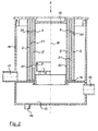
- FIG. 1 The drawing shows an oil mist separator 1 in a first embodiment in a vertical longitudinal section.
- the oil mist separator 1 comprises a housing 10 having a raw gas inlet 11 for crankcase ventilation gas coming from a crankcase of an associated internal combustion engine, a clean gas outlet 12 for de-oiled crankcase ventilation gas, and an oil collection area 13 located at the bottom of the housing 10 with an oil drain 14 for oil separated from the crankcase ventilation gas.
- a hollow cylindrical Diffusionsabscheide endeavor 2 is arranged, which has in its upper region a plurality of distributed over its circumference arranged through the gas channels 20.
- the diffusion separation body 2 is made of a fiber material or foam material or sintered material which is permeable to the crankcase ventilation gas and precipitates the oil mist entrained in the crankcase ventilation gas in the form of fine oil particles from the gas flow by diffusion deposition.
- a further diffusion separation body 2 ' is arranged at a distance from the diffusion separation body 2, which also has a hollow cylindrical shape, but has a lower height than the first diffusion separation body 2.
- Both diffusion separation bodies 2 and 2' are concentric to each other and to a central axis 19 of the oil mist separator 1 arranged.
- Diffusionsabscheide beneficia 2 and 2 ' connected to a housing 10 on the top closing lid 15, for example, glued or welded.
- an annular gap 21 is kept free.
- the outer, higher diffusion separation body 2 is with its lower end face on a base plate 16 and is also connected to this, preferably glued or welded.
- the radially inner diffusion separator body 2 'terminates at a downward distance from the base plate 16.
- the base plate 16 is pierced at its center to provide a flow path for the deoiled crankcase ventilation gas to the clean gas outlet 12.
- the diffusion separation bodies 2 and 2 ' are not yet loaded with oil and other substances entrained in the crankcase ventilation gas, so that they provide a low flow resistance for the crankcase ventilation gas.
- the crankcase ventilation gas flows in a predominant proportion and at low speed through the diffusion separation bodies 2 and 2 ', whereby the entrained oil is separated from the gas by diffusion deposition.
- the partial flow of the gas, which flows through the gas channels 20, then flows through the second diffusion separation body 2 ', whereby this gas partial stream is effectively de-oiled by diffusion deposition.
- the separated oil flows downward under gravity and passes through the perforated base plate 16 into the oil collection region 13, from where it is preferably returned to the crankcase of the associated internal combustion engine by the oil drain 14.
- the diffusion separation body 2 and 2 ' in each state the diffusion separation body 2 and 2 'has an effective oil mist separation, whereby first the oil mist separation takes place by deposition of the oil within the diffusion separation bodies 2 and 2' by diffusion deposition; With increasing loading of the diffusion separation body 2 and 2 ', the gas flow through the gas channels 20 increases, wherein an oil separation by impingement occurs in the surface regions 3. This is an effective oil mist separation and sufficient crankcase ventilation ensures over a very long period of operation, which avoids interference and damage to the associated internal combustion engine.
- crankcase ventilation gas flows substantially radially from outside to inside through the diffusion separation bodies 2 and 2' and then from the interior of the inner diffusion separation body 2 'axially down through the perforated base plate 16 to the clean gas outlet 12.
- the cross section and the number of gas channels 20 are selected such that that even at maximum laden Diffusionsabscheide redesignn 2 and 2 'still a sufficient derivative of crankcase ventilation gas is guaranteed and a maximum allowable pressure drop across the oil mist separator 1 is not exceeded.
- the gas channels 20 are self-cleaning due to the relatively high gas velocities occurring therein, so that there is no danger of blockage of the gas channels 20 even after a long period of operation.
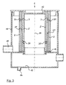
- FIG. 2 shows further embodiments of the oil mist separator 1, wherein in the left and in the right half of FIG. 2 two different versions are shown.
- the housing 10 with the Rohgaseinlass 11, the clean gas outlet 12, the oil collection area 13 and the oil discharge 14 and the lid 15 corresponds to the example according to FIG. 1 ,
- both diffusion separation bodies 2 and 2' together with their lower end face stand on the base plate 16.
- the radially outer diffusion separation body 2 is in the example according to Figure 2 with the example according to FIG. 1 match.
- the radially inner separation body 2 ' has in its lower region, that is, with a relatively large axial offset from the gas channels 20 located at the top in the outer diffusion separation body 2, one or more gas passages 30 in the form of relatively large openings.
- the gas passages 30 allow a low-resistance gas flow, so that the flow resistance of the oil mist separator 1 is kept advantageously low overall, even if the Diffusionsabscheide beneficia 2 and 2 'are heavily loaded.
- a further impact separation surface 4 ' may be provided radially inward of the gas passage 30.
- the impact separation surface 4 ' has a radially outer surface 3' of an annular, hollow cylindrical baffle plate as a deposition effective area, which is here in the circumferential direction into a plurality of sections, in particular per gas passage 30 a section divided.
- About radially resilient, axially extending connecting webs are the portions of the baffle plate 4 'is connected to the base plate 16 to hold it in the position shown and at the same time to allow a resilient movement in the radial direction.
- the impact separation surface 4 'initially abuts radially inward on the inner diffusion separation body 2' and then covers the gas passage 30.
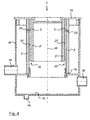
- FIG. 3 shows an embodiment of the oil mist separator 1, which in many parts with the in the FIG. 2 in the right half of the embodiment shown matches. It is different that in the example of the oil mist separator 1 after FIG. 3 the gas passages 30 are formed by inclined channels, wherein the channels 30 are designed to run obliquely downward in the radial direction from the outside inwards. As a result, in the region of the gas passages 30, sharp flow deflections which would lead to an increase in the flow resistance are avoided. Otherwise corresponds to the embodiment of the oil mist separator 1 according to FIG. 3 the examples described above.
- FIG. 4 shows an embodiment of the oil mist separator 1, which in many parts the embodiment of the oil mist separator 1 according to FIG. 1 equivalent.
- the base plate 16 is designed differently.
- the base plate has a maximum large central opening, whereby a particularly large flow cross-section is provided for the deoiled crankcase ventilation gas flowing out of the inner region of the inner diffusion separator body 2 'and out of the annular gap 21 on the way to the clean gas outlet 12.
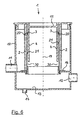
- FIG. 5 shows an example of the oil mist separator 1, in which the Diffusionsabscheide beneficia 2 and 2 'are made flat and plate-shaped.
- the two diffusion separation bodies 2 and 2 ' are likewise arranged here in a housing 10 into which the crankcase ventilation gas to be de-oiled is introduced via the raw gas inlet 11.
- the oil separation is wholly or largely predominantly within the Diffusionsabscheide endeavor 2 and 2' by diffusion deposition.
- an increasingly larger partial flow of the crankcase ventilation gas also flows through the gas channels 20 provided in the upper region of the first diffusion separation body 2.
- the gas channels 20 are in accordance with the present example FIG. 5 arranged perpendicular to the plane of the drawing one behind the other, whereby FIG. 5 only a single gas channel 20 is visible.
- crankcase ventilation gas stream flowing through the gas passages 20 strikes the surface 3, which is formed here by the surface of the second diffusion separation body 2 'facing the first diffusion separation body 2.
- the crankcase ventilation gas then flows partly through the second diffusion separation body 2 'according to FIG FIG. 5 to the right and partly through the gap 21 'between the Diffusionsabscheide benefician 2 and 2 'down and then through the at least one gas passage 30 in the second Diffusionsabscheide redesign 2' also to the right, from where the now de-oiled crankcase ventilation gas can flow through the total clean gas outlet 12.
- a lower portion of the housing 1 also forms an oil collection area 13, from where the separated oil can be removed by the oil discharge 14.
- Diffusionsabscheide endeavor 2 For holding and positioning the two flat, plate-shaped Diffusionsabscheide endeavor 2, 2 ' also serves a base plate 16, on which the two Diffusionsabscheide endeavor 2 and 2' are with their lower edge or lower edge. Further positioning takes place through the cover 15, which is connected on its underside to the upper edge of the two diffusion separation bodies 2 and 2 '.
- the Diffusionsabscheide endeavor 2 and 2 'thus together with the lid 15 also form an interconnected unit, which allows a simple replacement of Diffusionsabscheide redesign 2 and 2' in the context of maintenance.
- the exemplary embodiment of the oil mist separator 1 shown has only a single diffusion separation body 2.
- This diffusion separation body 2 is here again, similar to the examples according to FIGS FIGS. 1 to 4 , designed as a hollow cylinder.
- a hollow-cylindrical impact separation surface 4 Radially inwardly from the diffusion separation body 2 there is likewise arranged a hollow-cylindrical impact separation surface 4 with a radially outer, deposit-effective surface 3, which, like the diffusion separation body 2, extends concentrically to the central axis 19 of the oil mist separator 1.
- the hollow-cylindrical impact separation surface 4 is designed here in one piece with the lid 15 of the housing 10 for reasons of simple production.
- crankcase ventilation gas flows completely or largely predominantly through the diffusion separation body 2, whereby the entrained oil particles within the diffusion separation body 2 are deposited by diffusion deposition.
- crankcase ventilation gas With increasing loading of the diffusion separation body 2, an increasingly larger proportion of the crankcase ventilation gas also flows through the gas passages 20, which also run through the latter in the radial direction in the upper region of the diffusion separation body 2.
- the radially outer surface 3 of the Prallabscheide simulation 4 now forms the surface on which the flowing through the gas channels 20 partial flows of the crankcase ventilation gas, whereby an impact separation of entrained oil particles from the gas flow is effected.
- Severed oil flows here under gravity into the trained below in the housing 10 oil collection area 13, from where again an oil discharge 14 dissipates the collected oil.
- the diffusion separation body 2 is also connected at its upper front end to the underside of the lid 15 here.
- the lower end of the DiffusionsabscheideSchs 2 is connected to the base plate 16, whereby the Diffusionsabscheidelik 2, the lid 15 with the baffle plate 4 and the base plate 16 form an exchangeable unit.
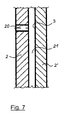
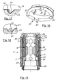
- FIG. 7 shows in enlarged scale a detail of one of the oil mist separator according to the FIGS. 1 to 5 ,
- the detail shows according to FIG. 7 a detail of the two Diffusionsabscheide redesignn 2 and 2 'with a running through the Diffusionsabscheide endeavor 2 gas channel 20.
- the gas channel 20 formed directly in the Diffusionsabscheide redesign 2, for example, by melting or welding or drilling or punching.
- a solidified surface of the gas channels 20 is advantageously obtained when the gas channels 20 melt, which gives them good dimensional stability without special measures.
- FIG. 8 shows in the same representation as the FIG. 7 a modified version.
- the difference to FIG. 7 is that in the example after FIG. 8 in the annular gap 21 between the two Diffusionsabscheide redesignn 2 and 2 ', a support body 5 is arranged.
- This support body 5 is expediently formed by a three-dimensional grid which keeps the annular gap 21 open and avoids deformation of the diffusion separation body 2 and 2 'during operation.
- the spatial structure of the support body 5 is of course designed so that a possible low-resistance flow through the crankcase ventilation gas along the annular gap 21 remains possible.
- the support body 5 may have a flow-guiding function and / or oil-separating function by a corresponding shape and structure.
- FIG. 9 shows again in the same representation as the FIGS. 7 and 8th another embodiment.
- the gas channels 20 are formed here by sleeves 22 inserted into the first diffusion separation body 2.
- the gas channels 20 receive a permanently resistant contour, which can also be produced with high accuracy.
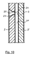
- FIG. 10 shows in the same representation as the FIGS. 7 to 9 an example in which the gas channels 20 upstream, that is in FIG. 10 on the left, are formed with an inflow funnel 23. Relative to that forms in the gas flow direction subsequent, ie in FIG. 10 right part of the gas channel 20 a constriction 24, whereby the gas channel 20 acts like a nozzle.
- FIG. 11 shows a modification of the embodiment according to FIG. 1 , where in the left half of FIG. 11 a Prallabscheide Chemistry 4 held in a resilient bearing 40 with a gas channel 20 facing surface 3 is shown.
- the surface 3 is under the action of a spring of the bearing 40 on the radially inner side of the DiffusionsabscheideSchs 2 and covers the gas channel 20.
- the entire gas flow now forcibly flows through the Diffusionsabscheide endeavor 2 and at least a partial flow of the gas subsequently the inner, further diffusion separation body 2 '.
- the impact separation surface 4 as a leaf valve made of a flexible metal plate or nonwoven platelets or elastomer platelets, each loaded in the closing direction with a spring or equipped with an inherent restoring force. Shown is the leaf valve in its open position.
- the deposition-effective surface 3 here is the surface of the platelet facing the diffusion deposition body 2.
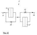
- FIG. 12 is a schematic diagram of the oil mist separator 1 according to FIG. 1 shown.
- On the left is the raw gas inlet 11, through which crankcase ventilation gas laden with oil mist is supplied.
- the gas stream flows through the diffusion separation body 2 and the free gas channels 20 in parallel, the latter acting as a throttle.
- the ratio of the partial flows adjusts according to the ratio of the flow resistances between the separation body 2 and the free gas channels 20.
- a fresh, unloaded separation body 2 by far the greater part of the gas flows through the separation body 2; With increasing loading of the separation body 2, an increasing part of the gas flows through the free gas channels 20, so that a gas flow is always ensured.
- crankcase ventilation gas stream Downstream of the second separation body 2' and the annular gap 21, the crankcase ventilation gas stream is reunited and now gets de-oiled in the clean gas outlet 12 also at strong or maximum laden AbscheideEff 2 and 2 'remains a sufficiently large flow cross-section through the gas channels 20 and the annular gap 21, so that always a sufficient crankcase ventilation is guaranteed. An impermissibly high pressure in the crankcase is thus reliably avoided.
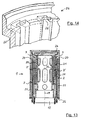
- FIG. 13 shows an example of a ⁇ lnebelabscheiders 1, which again has two concentrically arranged, hollow cylindrical Diffusionsabscheide endeavor 2 and 2 '.
- the separation bodies 2 and 2 ' are each formed by a fiber body 25, wherein the fiber bodies 25 are supported by a support body 26, which is designed here in several parts.
- the raw gas flows from radially outward and flows through first the outer diffusion separation body 2 and then the inner diffusion separation body 2 '.
- the free gas channels 20 are here in a transition region from the upper end face of the outer Abscheide stresses 2 to one of these facing side of the upper part of the support body 26 is formed.
- FIG. 14 shows in an enlarged section of the upper part of the support body 26 whose design.
- open grooves 26 'are formed which are bounded in the circumferential direction and upwards by the material of the support body 26 and which are initially open axially downwards.
- FIG. 15 also shows in a longitudinal section a further embodiment of the oil mist separator 1, which in other parts with the oil mist separator 1 according to FIG. 13 matches. The way is different, as in the oil mist separator 1 according to FIG. 15 the free gas channels 20 are formed.
- the support body 26 is formed in several parts with an upper, initially separate support member 27 which is connected to the rest of the support body 26, here latched, is.
- the support body part 27 has at its upper end face of the fiber body 25 of the outer Diffusionsabscheide endeavor 2 side facing in the circumferential direction distributed in the axial direction downwardly projecting lugs 27 'or lugs or the like suitable projections. These lugs 27 ensure that when attaching the support member 27, the material of the fiber body 25 is partially compressed in the axial direction. Since the cleats 27 'according to FIG. 16 On one side very steep, ie executed with an approximately perpendicular to the end face of the support member 27 extending slope, the material of the fiber body 25 of this slope can not follow, whereby the desired free gas channels 20 are formed.
- FIG. 17 shown in an enlarged detail.
- Top in the FIG. 17 is a section of the support member 27 can be seen, from which one of the lugs 27 'protrudes downward.
- FIG. 18 shows a modification of the support member 27 from FIG. 16 .
- FIG. 18 are pairs of two studs 27 'are provided instead of individual studs 27', which are mirror-symmetrical to each other, the steep flanks of the studs 27 'facing each other. In this way, approximately rectangular or square gas passages 20 are each cleared in the cross section when attaching the support member 27 on the rest of the support body 26 and kept free.
Landscapes
- Engineering & Computer Science (AREA)
- Chemical & Material Sciences (AREA)
- Chemical Kinetics & Catalysis (AREA)
- Mechanical Engineering (AREA)
- General Engineering & Computer Science (AREA)
- Lubrication Details And Ventilation Of Internal Combustion Engines (AREA)
Claims (30)
- Séparateur de vapeur d'huile (1) d'un moteur à combustion interne, avec au moins un corps de séparation par diffusion (2) perméable au gaz, pouvant être parcouru par le gaz de purge de vilebrequin du moteur à combustion interne dans lequel de la vapeur d'huile contenue dans le gaz de purge de vilebrequin peut être séparée du gaz,
caractérisé en ce
que des canaux de gaz libres continus (20) sont réalisés en outre dans le/chaque corps de séparation par diffusion (2) et qu'au moins un autre corps de séparation par diffusion (2') ou une surface de séparation par rebondissement (4) est disposé(e) derrière les canaux de gaz (20), vus dans le sens d'écoulement du gaz de purge de vilebrequin, à distance du/de chaque corps de séparation par diffusion (2). - Séparateur de vapeur d'huile selon la revendication 1, caractérisé en ce que les canaux de gaz (20) s'étendent perpendiculairement à un plan superficiel du corps de séparation par diffusion (2) et que l'autre corps de séparation par diffusion (2') ou la surface de séparation par rebondissement (4) s'étend parallèlement au plan superficiel du corps de séparation par diffusion (2).
- Séparateur de vapeur d'huile selon la revendication 1 ou 2, caractérisé en ce que l'autre corps de séparation par diffusion (2') ou la surface de séparation par rebondissement (4) présente au moins un passage de gaz (30) décalé par rapport aux canaux de gaz (20) du corps de séparation par diffusion (2).
- Séparateur de vapeur d'huile selon la revendication 3, caractérisé en ce qu'au moins un autre corps de séparation par diffusion (2") ou une autre surface de séparation par rebondissement (4') est disposé(e) derrière le passage de gaz (30), vu dans le sens d'écoulement du gaz de purge de vilebrequin, à distance de celui-ci.
- Séparateur de vapeur d'huile selon une des revendications 1 à 4, caractérisé en ce que la surface de séparation par rebondissement (4) ou au moins une des surfaces de séparation par rebondissement (4, 4') est formée par une plaque de rebondissement fermée, étanche au gaz et à l'huile.
- Séparateur de vapeur d'huile selon une des revendications 1 à 5, caractérisé en ce que le corps de séparation par diffusion (2) ou les corps de séparation par diffusion (2, 2') et la surface de séparation par rebondissement (4) ou les surfaces de séparation par rebondissement (4, 4') ont chacun une forme cylindrique creuse et sont disposés de manière concentrique les uns par rapport aux autres autour d'un axe médian (19).
- Séparateur de vapeur d'huile selon une des revendications 1 à 5, caractérisé en ce que le corps de séparation par diffusion (2) ou les corps de séparation par diffusion (2, 2') et la surface de séparation par rebondissement (4) ou les surfaces de séparation par rebondissement (4, 4') sont chacun disposés en forme de spirale, vus en coupe transversale.
- Séparateur de vapeur d'huile selon une des revendications 1 à 6, caractérisé en ce que le corps de séparation par diffusion (2) ou les corps de séparation par diffusion (2, 2') et la plaque de rebondissement (4) ou les plaques de rebondissement (4, 4') ont une forme plane plate et sont disposés parallèlement les uns aux autres.
- Séparateur de vapeur d'huile selon une des revendications 1 à 8, caractérisé en ce qu'au moins un corps d'appui perméable au gaz et à l'huile (5) est disposé entre les corps de séparation par diffusion (2, 2') ou entre le corps de séparation par diffusion (2, 2') et la surface de séparation par rebondissement disposée en aval (4).
- Séparateur de vapeur d'huile selon la revendication 9, caractérisé en ce que le corps d'appui (5) est formé par une grille tridimensionnelle.
- Séparateur de vapeur d'huile selon la revendication 9 ou 10, caractérisé en ce que le corps d'appui (5) a une forme et/ou structure qui a une fonction conductrice de gaz pour le gaz parcourant le corps d'appui (5) et/ou une fonction de séparation pour la vapeur d'huile contenue dans le gaz parcourant le corps d'appui (5).
- Séparateur de vapeur d'huile selon une des revendications 1 à 11, caractérisé en ce que le ou chaque corps de séparation par diffusion (2, 2') présente au moins un corps en fibres ou mousse (25).
- Séparateur de vapeur d'huile selon la revendication 12, caractérisé en ce qu'un matériau formant le corps en fibres ou mousse (25) est en forme de bande dans un état de départ et présente une épaisseur assez faible en tant que corps en fibres ou mousse (25), et que le matériau en forme de bande est enroulé en le corps en fibres ou mousse (25).
- Séparateur de vapeur d'huile selon la revendication 12 et la revendication 9 ou 10, caractérisé en ce qu'un matériau formant le corps en fibres ou mousse (25) est en forme de bande dans un état de départ et présente une épaisseur correspondant à l'épaisseur du corps en fibres ou mousse (25), et que le matériau en forme de bande est enroulé avec le corps d'appui également en forme de bande dans un état de départ sous forme de spirale en le corps en fibres ou mousse (25) ou en plusieurs corps en fibres ou mousse (25).
- Séparateur de vapeur d'huile selon la revendication 12, caractérisé en ce que le/chaque corps en fibres ou mousse (25) a la forme d'un profil creux, de préférence d'un cylindre creux.
- Séparateur de vapeur d'huile selon une des revendications 12 à 14, caractérisé en ce que le ou chaque corps de séparation par diffusion (2, 2') présente un corps porteur (26) portant le(s) corps en fibres ou mousse (25), outre l'au moins un corps en fibres ou mousse (25).
- Séparateur de vapeur d'huile selon une des revendications 12 à 16, caractérisé en ce que le ou chaque corps en fibres (25) est fabriqué à partir d'un matériau de feutre en fibres synthétiques thermoplastiques ou thermodurcissables ou fibres métalliques ou fibres de carbone ou fibres de verre ou à partir d'un matériau de papier.
- Séparateur de vapeur d'huile selon une des revendications 12 à 16, caractérisé en ce que le corps en fibres (25) est fabriqué à partir d'un non tissé ou tissu ou d'une tige oscillante ou d'un tissu à mailles ou tricot en fibres synthétiques thermoplastiques ou thermodurcissables ou fibres métalliques ou fibres de carbone ou fibres de verre.
- Séparateur de vapeur d'huile selon la revendication 12, caractérisé en ce que le corps en mousse est fabriqué à partir d'une mousse synthétique ou métallique ou de verre.
- Séparateur de vapeur d'huile selon la revendication 19, caractérisé en ce que le corps en mousse est fabriqué à partir d'un plastique de mousse thermoplastique ou thermodurcissable à cellules ouvertes.
- Séparateur de vapeur d'huile selon une des revendications 1 à 11, caractérisé en ce que le ou chaque corps de séparation par diffusion (2, 2') présente au moins un corps fritté.
- Séparateur de vapeur d'huile selon une des revendications 1 à 21, caractérisé en ce que les canaux de gaz (20) sont fondus ou soudés ou percés ou estampés ou plongés ou découpés directement dans le matériau du corps en fibres (25) ou corps en mousse ou corps fritté.
- Séparateur de vapeur d'huile selon une des revendications 1 à 21, caractérisé en ce que les canaux de gaz (20) sont formés à travers des manchons (22) insérés dans le matériau du corps en fibres (25) ou corps en mousse ou corps fritté.
- Séparateur de vapeur d'huile selon une des revendications 1 à 21, caractérisé en ce que les canaux de gaz (20) sont disposés dans une région de transition entre au moins une extrémité frontale ou un bord du corps en fibres (25) ou corps en mousse ou corps fritté et une région voisine de celui-ci du corps porteur associé (26).
- Séparateur de vapeur d'huile selon la revendication 24, caractérisé en ce que le corps porteur (26) présente sur son côté tourné vers le corps en fibres (25) ou corps en mousse ou corps fritté des rainures (26') ouvertes vers celui-ci qui sont limitées par l'extrémité frontale ou le bord du corps en fibres (25) ou corps en mousse ou corps fritté par rapport aux canaux de gaz (20).
- Séparateur de vapeur d'huile selon la revendication 24, caractérisé en ce que le corps porteur (26) est en deux ou plusieurs parties et qu'une partie de corps porteur (27) possède sur son côté tourné vers l'extrémité frontale ou le bord du corps en fibres (25) ou corps en mousse ou corps fritté une ou plusieurs cannelures saillantes (27') ou paires de cannelures (27') qui enfoncent partiellement du côté du bord à l'état relié des parties de corps porteur (26, 27) le corps en fibres (25) ou corps en mousse ou corps fritté et forment ainsi les canaux de gaz (20).
- Séparateur de vapeur d'huile selon une des revendications 1 à 26, caractérisé en ce que les canaux de gaz (20) sont réalisés avec un rétrécissement de type buse (24) du côté de la sortie.
- Séparateur de vapeur d'huile selon une des revendications 1 à 27, caractérisé en ce que l'autre corps de séparation par diffusion (2') ou encore l'autre corps de séparation par diffusion (2") ou la surface de séparation par rebondissement (4) ou au moins une des surfaces de séparation par rebondissement (4, 4') ou à chaque fois une partie de ceux-ci peuvent être réglés par rapport aux canaux de gaz (20) ou par rapport au passage de gaz (30) à l'encontre d'une force de rappel de sorte qu'en cas de pression différentielle au-dessus du séparateur de vapeur d'huile (1) en dessous d'une valeur limite pouvant être prédéfinie, les canaux de gaz (20) et le passage de gaz (30) sont fermés par l'autre corps de séparation par diffusion (2') ou encore l'autre corps de séparation par diffusion (2") ou la surface de séparation par rebondissement (4), et qu'en cas de pression différentielle au-dessus du séparateur de vapeur d'huile (1) au-dessus d'une valeur limite pouvant être prédéfinie, les canaux de gaz (20) et le passage de gaz (30) sont ouverts par coulissement de l'autre corps de séparation par diffusion (2') ou encore de l'autre corps de séparation par diffusion (2") ou de la/des surface(s) de séparation par rebondissement (4, 4') à l'encontre de la force de rappel.
- Séparateur de vapeur d'huile selon une des revendications 1 à 27, caractérisé en ce qu'au moins une soupape séparée (41) est associée aux canaux de gaz (20) ou au passage de gaz (30).
- Séparateur de vapeur d'huile selon une des revendications 1 à 29, caractérisé en ce que le séparateur de vapeur d'huile (1) présente un logement qui est fermé en fonctionnement avec un couvercle de logement amovible (15), et que le ou les corps de séparation par diffusion (2, 2', 2") forment une unité modulaire permutable.
Applications Claiming Priority (2)
| Application Number | Priority Date | Filing Date | Title |
|---|---|---|---|
| DE202007014378U DE202007014378U1 (de) | 2007-10-12 | 2007-10-12 | Ölnebelabscheider einer Brennkraftmaschine |
| PCT/EP2008/008528 WO2009049818A1 (fr) | 2007-10-12 | 2008-10-09 | Séparateur de vapeur d'huile d'un moteur à combustion interne |
Publications (2)
| Publication Number | Publication Date |
|---|---|
| EP2201224A1 EP2201224A1 (fr) | 2010-06-30 |
| EP2201224B1 true EP2201224B1 (fr) | 2015-04-15 |
Family
ID=40351554
Family Applications (1)
| Application Number | Title | Priority Date | Filing Date |
|---|---|---|---|
| EP08838747.7A Active EP2201224B1 (fr) | 2007-10-12 | 2008-10-09 | Séparateur de vapeur d'huile d'un moteur à combustion interne |
Country Status (5)
| Country | Link |
|---|---|
| US (1) | US8449637B2 (fr) |
| EP (1) | EP2201224B1 (fr) |
| CN (1) | CN102317585B (fr) |
| DE (1) | DE202007014378U1 (fr) |
| WO (1) | WO2009049818A1 (fr) |
Cited By (1)
| Publication number | Priority date | Publication date | Assignee | Title |
|---|---|---|---|---|
| WO2018024469A1 (fr) | 2016-08-05 | 2018-02-08 | Mann+Hummel Gmbh | Élément de séparation, dispositif et procédé de séparation de liquide présent dans du gaz brut ou dans un mélange de gaz brut d'un moteur/compresseur |
Families Citing this family (42)
| Publication number | Priority date | Publication date | Assignee | Title |
|---|---|---|---|---|
| DE102007062098A1 (de) * | 2007-12-21 | 2009-06-25 | Mahle International Gmbh | Ölnebelabscheider |
| DE102009024701B4 (de) | 2009-06-12 | 2016-05-04 | Mahle International Gmbh | Ölnebelabscheider |
| DE102009048068A1 (de) * | 2009-10-01 | 2011-04-07 | Valeo Klimasysteme Gmbh | Ansaugeinheit einer Fahrzeugklimaanlage |
| EP2587009B1 (fr) * | 2010-06-24 | 2017-11-08 | Tokyo Roki Co., Ltd. | Séparateur de brouillard d'huile |
| JP5482514B2 (ja) | 2010-06-30 | 2014-05-07 | トヨタ紡織株式会社 | オイルセパレータ |
| US20120255375A1 (en) * | 2011-04-11 | 2012-10-11 | LMS Technologies, Inc. | Apparatuses and methods for capturing and retaining particles |
| JP5791384B2 (ja) * | 2011-06-16 | 2015-10-07 | 株式会社テイエルブイ | 気液分離器 |
| US8236092B1 (en) * | 2011-06-27 | 2012-08-07 | Richards Clyde N | Pressure gradient gas scrubber apparatus and method |
| DE102011087146A1 (de) * | 2011-11-25 | 2013-05-29 | Mahle International Gmbh | Ölabscheider |
| CN104302878B (zh) | 2012-02-27 | 2020-03-13 | 纳博特斯克汽车零部件有限公司 | 具备压缩机、空气干燥器以及油分离器的系统 |
| WO2013129495A1 (fr) * | 2012-02-27 | 2013-09-06 | ナブテスコオートモーティブ 株式会社 | Séparateur d'huile |
| US9656198B2 (en) | 2012-02-27 | 2017-05-23 | Nabtesco Automotive Corporation | Oil separator |
| DE102012008808B4 (de) * | 2012-05-07 | 2014-08-07 | Mann + Hummel Gmbh | Abscheidevorrichtung |
| CN104349829B (zh) | 2012-05-10 | 2016-02-17 | 纳薄特斯克汽车零部件有限公司 | 油分离器 |
| CN104641114B (zh) | 2012-07-02 | 2017-05-17 | 纳薄特斯克汽车零部件有限公司 | 油分离器 |
| US20140076661A1 (en) * | 2012-09-19 | 2014-03-20 | United Technologies Corporation | Lubrication system having porous feature |
| CN103084029A (zh) * | 2012-12-29 | 2013-05-08 | 苏州韩博厨房电器科技有限公司 | 一种油烟净化器 |
| CN103084030A (zh) * | 2012-12-29 | 2013-05-08 | 苏州韩博厨房电器科技有限公司 | 丝网碰撞油滴去除分离装置 |
| CN103084031A (zh) * | 2012-12-29 | 2013-05-08 | 苏州韩博厨房电器科技有限公司 | 去油溶剂喷淋装置 |
| DE202013008611U1 (de) * | 2013-09-26 | 2014-09-29 | Reinz-Dichtungs-Gmbh | Entlüftungssystem für aufgeladene Brennkraftmaschinen |
| US9732707B1 (en) | 2013-12-09 | 2017-08-15 | High Output Technology, LLC | Vent for engine crankcases |
| US8968446B1 (en) * | 2014-03-06 | 2015-03-03 | UPR Products, Inc. | Oil and air separation system and method |
| US10843112B2 (en) * | 2014-08-29 | 2020-11-24 | Nabtesco Automotive Corporation | Oil separator and compressed air drying system |
| AT516310B1 (de) | 2014-09-15 | 2016-06-15 | Ge Jenbacher Gmbh & Co Og | Filtereinsatz |
| JP6094555B2 (ja) * | 2014-10-02 | 2017-03-15 | トヨタ自動車株式会社 | オイル除去装置 |
| US20160208667A1 (en) * | 2015-01-16 | 2016-07-21 | Caterpillar Inc. | Engine emission absorber assembly and method for operating same |
| DE102015205216A1 (de) * | 2015-03-23 | 2016-05-19 | Mtu Friedrichshafen Gmbh | Abscheideeinrichtung, Kurbelgehäuse-Entlüftung für eine Brennkraftmaschine und Brennkraftmaschine |
| DE102016006095B4 (de) * | 2015-07-16 | 2023-05-25 | Mann+Hummel Gmbh | Abscheidemodul, Leitungsmodul sowie Entlüftungsvorrichtung |
| DE102016100419B4 (de) * | 2016-01-12 | 2019-07-04 | BRUSS Sealing Systems GmbH | Ölabscheidevorrichtung für die Kurbelgehäuseentlüftung eines Verbrennungsmotors |
| US20170225109A1 (en) * | 2016-02-10 | 2017-08-10 | United Air Specialists, Inc. | Nested filter for use in a mist coalescer unit |
| CN105697600A (zh) * | 2016-03-01 | 2016-06-22 | 宁波华盛联合制动科技有限公司 | 一种液力缓速器的油气分离装置 |
| CN105697592A (zh) * | 2016-03-01 | 2016-06-22 | 宁波华盛联合制动科技有限公司 | 液力缓速器的油气分离装置 |
| CN105756761A (zh) * | 2016-04-14 | 2016-07-13 | 王东明 | 多级变换流速滤烟器 |
| WO2018011749A1 (fr) * | 2016-07-15 | 2018-01-18 | MARQUES RODRIGUES, Carlos Jorge | Séparateur d'huile pour gaz à partir de la tête d'un moteur à combustion interne d'un véhicule, système le contenant et son procédé d'installation |
| US10596509B2 (en) * | 2016-07-22 | 2020-03-24 | Mann+Hummel Gmbh | Ring filter element, in particular for oil separation of a crankcase, and filter device |
| GB2552986B (en) | 2016-08-17 | 2020-09-16 | Nifco Inc | A device for separating oil from a blow-by gas |
| DE102016218357A1 (de) | 2016-09-23 | 2018-03-29 | Mahle International Gmbh | Abscheideeinrichtung |
| US10837376B2 (en) * | 2016-09-28 | 2020-11-17 | Transportation Ip Holdings, Llc | Systems for diagnosing a condition of an engine |
| CN109772077B (zh) * | 2017-11-13 | 2023-11-10 | 新乡航空工业(集团)有限公司 | 气体过滤单元、轨道车辆及其空气过滤器 |
| US11047274B2 (en) * | 2018-11-14 | 2021-06-29 | GM Global Technology Operations LLC | Air-oil separator |
| DE102019201046B4 (de) * | 2019-01-28 | 2023-03-02 | Mahle International Gmbh | Ölnebelabscheider und Kurbelgehäuseentlüftungseinrichtung |
| US12241461B2 (en) * | 2022-08-23 | 2025-03-04 | Bauer Compressors, Inc. | Compressor crankcase oil reclamation system |
Citations (1)
| Publication number | Priority date | Publication date | Assignee | Title |
|---|---|---|---|---|
| JPH02127722U (fr) * | 1989-03-30 | 1990-10-22 |
Family Cites Families (19)
| Publication number | Priority date | Publication date | Assignee | Title |
|---|---|---|---|---|
| US3712030A (en) * | 1970-09-14 | 1973-01-23 | J Priest | Exhaust depurator |
| JPS60173614U (ja) * | 1984-04-27 | 1985-11-18 | 日産ディーゼル工業株式会社 | エンジンのオイルセパレ−タ |
| US4627406A (en) * | 1984-12-05 | 1986-12-09 | Kabushiki Kaisha Tsuchiya Seisakusho | Oil separator for recycled blow-by gas |
| DE3910559A1 (de) * | 1989-04-01 | 1990-10-04 | Bayerische Motoren Werke Ag | Oelabscheider mit labyrinthartiger stroemungsfuehrung |
| US5024203A (en) * | 1990-08-22 | 1991-06-18 | Sealed Power Technologies, L.P. | PCV oil separator system |
| JPH0630456U (ja) * | 1992-09-24 | 1994-04-22 | 株式会社土屋製作所 | 合成樹脂製のシリンダヘッドカバー |
| JPH06193424A (ja) * | 1992-12-25 | 1994-07-12 | Toyoda Spinning & Weaving Co Ltd | ブローバイガス用オイル分離装置 |
| JP3313553B2 (ja) * | 1995-09-29 | 2002-08-12 | 株式会社 マーレ テネックス | オイルミストセパレータ |
| US5669366A (en) | 1996-07-10 | 1997-09-23 | Fleetguard, Inc. | Closed crankcase ventilation system |
| DE29700579U1 (de) * | 1997-01-15 | 1997-03-13 | Mann & Hummel Filter | Anordnung zum Abscheiden von Flüssigkeitspartikeln aus einem Gasstrom |
| DE19803094A1 (de) * | 1998-01-28 | 1999-08-05 | Bosch Gmbh Robert | Reinigungsvorrichtung zum Abscheiden von Partikeln aus einem Gasstrom |
| DE19824041A1 (de) * | 1998-05-29 | 1999-12-02 | Stihl Maschf Andreas | Verbrennungsmotor |
| JP2000274225A (ja) * | 1999-03-25 | 2000-10-03 | Toyota Autom Loom Works Ltd | ブローバイガス用オイルセパレータ |
| US6290738B1 (en) | 1999-07-16 | 2001-09-18 | Nelson Industries, Inc. | Inertial gas-liquid separator having an inertial collector spaced from a nozzle structure |
| JP2003301710A (ja) * | 2002-04-08 | 2003-10-24 | Toyota Industries Corp | オイルセパレータ及び内燃機関 |
| US7473291B2 (en) | 2004-09-21 | 2009-01-06 | Cummins Filtration Ip, Inc. | Inertial gas-liquid separator with variable flow actuator |
| DE102005042286A1 (de) * | 2005-09-06 | 2007-04-12 | Mahle International Gmbh | Einrichtung zur Trennung eines Gas-Flüssigkeitsgemisches |
| US7604676B2 (en) | 2006-02-02 | 2009-10-20 | Detroit Diesel Corporation | Inertial impactor for closed crankcase ventilation |
| DE102006041213B4 (de) * | 2006-09-02 | 2017-06-29 | Mahle International Gmbh | Einrichtung zur Kurbelraumentlüftung |
-
2007
- 2007-10-12 DE DE202007014378U patent/DE202007014378U1/de not_active Expired - Lifetime
-
2008
- 2008-10-09 EP EP08838747.7A patent/EP2201224B1/fr active Active
- 2008-10-09 US US12/682,320 patent/US8449637B2/en not_active Expired - Fee Related
- 2008-10-09 WO PCT/EP2008/008528 patent/WO2009049818A1/fr not_active Ceased
- 2008-10-09 CN CN200880111146.6A patent/CN102317585B/zh active Active
Patent Citations (1)
| Publication number | Priority date | Publication date | Assignee | Title |
|---|---|---|---|---|
| JPH02127722U (fr) * | 1989-03-30 | 1990-10-22 |
Cited By (3)
| Publication number | Priority date | Publication date | Assignee | Title |
|---|---|---|---|---|
| WO2018024469A1 (fr) | 2016-08-05 | 2018-02-08 | Mann+Hummel Gmbh | Élément de séparation, dispositif et procédé de séparation de liquide présent dans du gaz brut ou dans un mélange de gaz brut d'un moteur/compresseur |
| DE102016009487A1 (de) | 2016-08-05 | 2018-02-08 | Mann + Hummel Gmbh | Abscheideelement, Vorrichtung sowie Verfahren zur Abscheidung von Flüssigkeit aus Rohgas oder aus Rohgasgemisch einer Kraftmaschine/Kompressors |
| DE102016009487B4 (de) | 2016-08-05 | 2024-07-04 | Mann+Hummel Gmbh | Abscheideelement, Vorrichtung sowie Verfahren zur Abscheidung von Flüssigkeit aus Rohgas oder aus Rohgasgemisch einer Kraftmaschine oder eines Kompressors |
Also Published As
| Publication number | Publication date |
|---|---|
| CN102317585A (zh) | 2012-01-11 |
| EP2201224A1 (fr) | 2010-06-30 |
| DE202007014378U1 (de) | 2009-02-26 |
| US8449637B2 (en) | 2013-05-28 |
| CN102317585B (zh) | 2016-03-09 |
| WO2009049818A1 (fr) | 2009-04-23 |
| US20100229510A1 (en) | 2010-09-16 |
Similar Documents
| Publication | Publication Date | Title |
|---|---|---|
| EP2201224B1 (fr) | Séparateur de vapeur d'huile d'un moteur à combustion interne | |
| EP2313620B1 (fr) | Dispositif de séparation de particules pour un écoulement d'aérosol | |
| DE102010029322B4 (de) | Druckbegrenzungsventil einer Vorrichtung zum Entlüften des Kurbelgehäuses einer Brennkraftmaschine und Vorrichtung mit einem solchen Druckbegrenzungsventil | |
| DE102011120653B4 (de) | Kraftstofffilter einer Brennkraftmaschine und Filterelement eines Kraftstofffilters | |
| EP2220347B1 (fr) | Séparateur de vapeur d'huile | |
| DE102009018000B4 (de) | Abscheider zum Abscheiden von Flüssigkeitströpfchen aus einem Aerosol | |
| EP1294466A2 (fr) | Piege a particules destine a extraire des particules d'un courant de fluide, procede d'extraction de particules d'un courant de fluide, et utilisation d'un piege a particules | |
| DE2510225A1 (de) | Abscheider zum abscheiden von fluessigkeit aus gasen | |
| DE102014016301A1 (de) | Hohlfilterelement eines Filters zur Filtrierung von Fluid, Filter, Filtergehäuse und Dichtung eines Hohlfilterelements | |
| DE10224224A1 (de) | Filterelement, insbesondere zur Flüssigkeitsfilterung | |
| DE112019005296T5 (de) | Luftfilterbaugruppe mit durchlässigem leitblech | |
| WO2018024469A1 (fr) | Élément de séparation, dispositif et procédé de séparation de liquide présent dans du gaz brut ou dans un mélange de gaz brut d'un moteur/compresseur | |
| EP3000520B1 (fr) | Insert de filtre | |
| DE102016008007A1 (de) | Abscheideelement eines Flüssigkeitsabscheiders, Abscheidemedium, Flüssigkeitsabscheider und Verfahren zur Herstellung eines Abscheideelements | |
| DE202012002218U1 (de) | Ölabscheider | |
| DE102016102309A1 (de) | Abscheidemediumkörper zur Verwendung in einem Abscheider | |
| DE102005027415B4 (de) | Ölabscheider für ein Kurbelgehäuse einer Brennkraftmaschine | |
| DE102022106035A1 (de) | Abscheidevorrichtung, Impaktorabscheid-Element und Gasstromreinigungsverfahren | |
| DE102011100239B4 (de) | Umgehungsvorrichtung eines Kurbelgehäuseentlüftungssystems | |
| WO2012065835A1 (fr) | Séparateur de particules pouvant être nettoyé | |
| DD142500A1 (de) | Filtereinrichtung | |
| DE1401246A1 (de) | Luftfilter |
Legal Events
| Date | Code | Title | Description |
|---|---|---|---|
| PUAI | Public reference made under article 153(3) epc to a published international application that has entered the european phase |
Free format text: ORIGINAL CODE: 0009012 |
|
| 17P | Request for examination filed |
Effective date: 20100511 |
|
| AK | Designated contracting states |
Kind code of ref document: A1 Designated state(s): AT BE BG CH CY CZ DE DK EE ES FI FR GB GR HR HU IE IS IT LI LT LU LV MC MT NL NO PL PT RO SE SI SK TR |
|
| AX | Request for extension of the european patent |
Extension state: AL BA MK RS |
|
| DAX | Request for extension of the european patent (deleted) | ||
| 17Q | First examination report despatched |
Effective date: 20120629 |
|
| RAP1 | Party data changed (applicant data changed or rights of an application transferred) |
Owner name: HENGST SE & CO. KG |
|
| GRAP | Despatch of communication of intention to grant a patent |
Free format text: ORIGINAL CODE: EPIDOSNIGR1 |
|
| INTG | Intention to grant announced |
Effective date: 20141103 |
|
| GRAS | Grant fee paid |
Free format text: ORIGINAL CODE: EPIDOSNIGR3 |
|
| GRAA | (expected) grant |
Free format text: ORIGINAL CODE: 0009210 |
|
| AK | Designated contracting states |
Kind code of ref document: B1 Designated state(s): AT BE BG CH CY CZ DE DK EE ES FI FR GB GR HR HU IE IS IT LI LT LU LV MC MT NL NO PL PT RO SE SI SK TR |
|
| REG | Reference to a national code |
Ref country code: GB Ref legal event code: FG4D Free format text: NOT ENGLISH Ref country code: CH Ref legal event code: EP |
|
| REG | Reference to a national code |
Ref country code: IE Ref legal event code: FG4D Free format text: LANGUAGE OF EP DOCUMENT: GERMAN |
|
| REG | Reference to a national code |
Ref country code: AT Ref legal event code: REF Ref document number: 722122 Country of ref document: AT Kind code of ref document: T Effective date: 20150515 |
|
| REG | Reference to a national code |
Ref country code: DE Ref legal event code: R096 Ref document number: 502008012894 Country of ref document: DE Effective date: 20150528 |
|
| REG | Reference to a national code |
Ref country code: NL Ref legal event code: VDEP Effective date: 20150415 |
|
| REG | Reference to a national code |
Ref country code: LT Ref legal event code: MG4D |
|
| PG25 | Lapsed in a contracting state [announced via postgrant information from national office to epo] |
Ref country code: NL Free format text: LAPSE BECAUSE OF FAILURE TO SUBMIT A TRANSLATION OF THE DESCRIPTION OR TO PAY THE FEE WITHIN THE PRESCRIBED TIME-LIMIT Effective date: 20150415 |
|
| PG25 | Lapsed in a contracting state [announced via postgrant information from national office to epo] |
Ref country code: NO Free format text: LAPSE BECAUSE OF FAILURE TO SUBMIT A TRANSLATION OF THE DESCRIPTION OR TO PAY THE FEE WITHIN THE PRESCRIBED TIME-LIMIT Effective date: 20150715 Ref country code: PT Free format text: LAPSE BECAUSE OF FAILURE TO SUBMIT A TRANSLATION OF THE DESCRIPTION OR TO PAY THE FEE WITHIN THE PRESCRIBED TIME-LIMIT Effective date: 20150817 Ref country code: LT Free format text: LAPSE BECAUSE OF FAILURE TO SUBMIT A TRANSLATION OF THE DESCRIPTION OR TO PAY THE FEE WITHIN THE PRESCRIBED TIME-LIMIT Effective date: 20150415 Ref country code: FI Free format text: LAPSE BECAUSE OF FAILURE TO SUBMIT A TRANSLATION OF THE DESCRIPTION OR TO PAY THE FEE WITHIN THE PRESCRIBED TIME-LIMIT Effective date: 20150415 Ref country code: ES Free format text: LAPSE BECAUSE OF FAILURE TO SUBMIT A TRANSLATION OF THE DESCRIPTION OR TO PAY THE FEE WITHIN THE PRESCRIBED TIME-LIMIT Effective date: 20150415 Ref country code: HR Free format text: LAPSE BECAUSE OF FAILURE TO SUBMIT A TRANSLATION OF THE DESCRIPTION OR TO PAY THE FEE WITHIN THE PRESCRIBED TIME-LIMIT Effective date: 20150415 |
|
| PG25 | Lapsed in a contracting state [announced via postgrant information from national office to epo] |
Ref country code: LV Free format text: LAPSE BECAUSE OF FAILURE TO SUBMIT A TRANSLATION OF THE DESCRIPTION OR TO PAY THE FEE WITHIN THE PRESCRIBED TIME-LIMIT Effective date: 20150415 Ref country code: IS Free format text: LAPSE BECAUSE OF FAILURE TO SUBMIT A TRANSLATION OF THE DESCRIPTION OR TO PAY THE FEE WITHIN THE PRESCRIBED TIME-LIMIT Effective date: 20150815 Ref country code: GR Free format text: LAPSE BECAUSE OF FAILURE TO SUBMIT A TRANSLATION OF THE DESCRIPTION OR TO PAY THE FEE WITHIN THE PRESCRIBED TIME-LIMIT Effective date: 20150716 |
|
| REG | Reference to a national code |
Ref country code: DE Ref legal event code: R097 Ref document number: 502008012894 Country of ref document: DE |
|
| PG25 | Lapsed in a contracting state [announced via postgrant information from national office to epo] |
Ref country code: DK Free format text: LAPSE BECAUSE OF FAILURE TO SUBMIT A TRANSLATION OF THE DESCRIPTION OR TO PAY THE FEE WITHIN THE PRESCRIBED TIME-LIMIT Effective date: 20150415 Ref country code: EE Free format text: LAPSE BECAUSE OF FAILURE TO SUBMIT A TRANSLATION OF THE DESCRIPTION OR TO PAY THE FEE WITHIN THE PRESCRIBED TIME-LIMIT Effective date: 20150415 |
|
| PLBE | No opposition filed within time limit |
Free format text: ORIGINAL CODE: 0009261 |
|
| STAA | Information on the status of an ep patent application or granted ep patent |
Free format text: STATUS: NO OPPOSITION FILED WITHIN TIME LIMIT |
|
| PG25 | Lapsed in a contracting state [announced via postgrant information from national office to epo] |
Ref country code: CZ Free format text: LAPSE BECAUSE OF FAILURE TO SUBMIT A TRANSLATION OF THE DESCRIPTION OR TO PAY THE FEE WITHIN THE PRESCRIBED TIME-LIMIT Effective date: 20150415 Ref country code: PL Free format text: LAPSE BECAUSE OF FAILURE TO SUBMIT A TRANSLATION OF THE DESCRIPTION OR TO PAY THE FEE WITHIN THE PRESCRIBED TIME-LIMIT Effective date: 20150415 Ref country code: SK Free format text: LAPSE BECAUSE OF FAILURE TO SUBMIT A TRANSLATION OF THE DESCRIPTION OR TO PAY THE FEE WITHIN THE PRESCRIBED TIME-LIMIT Effective date: 20150415 Ref country code: RO Free format text: LAPSE BECAUSE OF NON-PAYMENT OF DUE FEES Effective date: 20150415 |
|
| 26N | No opposition filed |
Effective date: 20160118 |
|
| PG25 | Lapsed in a contracting state [announced via postgrant information from national office to epo] |
Ref country code: IT Free format text: LAPSE BECAUSE OF FAILURE TO SUBMIT A TRANSLATION OF THE DESCRIPTION OR TO PAY THE FEE WITHIN THE PRESCRIBED TIME-LIMIT Effective date: 20150415 |
|
| PG25 | Lapsed in a contracting state [announced via postgrant information from national office to epo] |
Ref country code: SI Free format text: LAPSE BECAUSE OF FAILURE TO SUBMIT A TRANSLATION OF THE DESCRIPTION OR TO PAY THE FEE WITHIN THE PRESCRIBED TIME-LIMIT Effective date: 20150415 Ref country code: LU Free format text: LAPSE BECAUSE OF FAILURE TO SUBMIT A TRANSLATION OF THE DESCRIPTION OR TO PAY THE FEE WITHIN THE PRESCRIBED TIME-LIMIT Effective date: 20151009 |
|
| REG | Reference to a national code |
Ref country code: CH Ref legal event code: PL |
|
| GBPC | Gb: european patent ceased through non-payment of renewal fee |
Effective date: 20151009 |
|
| PG25 | Lapsed in a contracting state [announced via postgrant information from national office to epo] |
Ref country code: MC Free format text: LAPSE BECAUSE OF FAILURE TO SUBMIT A TRANSLATION OF THE DESCRIPTION OR TO PAY THE FEE WITHIN THE PRESCRIBED TIME-LIMIT Effective date: 20150415 |
|
| REG | Reference to a national code |
Ref country code: IE Ref legal event code: MM4A |
|
| PG25 | Lapsed in a contracting state [announced via postgrant information from national office to epo] |
Ref country code: LI Free format text: LAPSE BECAUSE OF NON-PAYMENT OF DUE FEES Effective date: 20151031 Ref country code: CH Free format text: LAPSE BECAUSE OF NON-PAYMENT OF DUE FEES Effective date: 20151031 Ref country code: GB Free format text: LAPSE BECAUSE OF NON-PAYMENT OF DUE FEES Effective date: 20151009 |
|
| REG | Reference to a national code |
Ref country code: FR Ref legal event code: ST Effective date: 20160630 |
|
| PG25 | Lapsed in a contracting state [announced via postgrant information from national office to epo] |
Ref country code: FR Free format text: LAPSE BECAUSE OF NON-PAYMENT OF DUE FEES Effective date: 20151102 |
|
| PG25 | Lapsed in a contracting state [announced via postgrant information from national office to epo] |
Ref country code: IE Free format text: LAPSE BECAUSE OF NON-PAYMENT OF DUE FEES Effective date: 20151009 |
|
| REG | Reference to a national code |
Ref country code: AT Ref legal event code: MM01 Ref document number: 722122 Country of ref document: AT Kind code of ref document: T Effective date: 20151009 |
|
| PG25 | Lapsed in a contracting state [announced via postgrant information from national office to epo] |
Ref country code: AT Free format text: LAPSE BECAUSE OF NON-PAYMENT OF DUE FEES Effective date: 20151009 |
|
| PG25 | Lapsed in a contracting state [announced via postgrant information from national office to epo] |
Ref country code: HU Free format text: LAPSE BECAUSE OF FAILURE TO SUBMIT A TRANSLATION OF THE DESCRIPTION OR TO PAY THE FEE WITHIN THE PRESCRIBED TIME-LIMIT; INVALID AB INITIO Effective date: 20081009 Ref country code: BG Free format text: LAPSE BECAUSE OF FAILURE TO SUBMIT A TRANSLATION OF THE DESCRIPTION OR TO PAY THE FEE WITHIN THE PRESCRIBED TIME-LIMIT Effective date: 20150415 |
|
| PG25 | Lapsed in a contracting state [announced via postgrant information from national office to epo] |
Ref country code: CY Free format text: LAPSE BECAUSE OF FAILURE TO SUBMIT A TRANSLATION OF THE DESCRIPTION OR TO PAY THE FEE WITHIN THE PRESCRIBED TIME-LIMIT Effective date: 20150415 Ref country code: SE Free format text: LAPSE BECAUSE OF FAILURE TO SUBMIT A TRANSLATION OF THE DESCRIPTION OR TO PAY THE FEE WITHIN THE PRESCRIBED TIME-LIMIT Effective date: 20150415 |
|
| PG25 | Lapsed in a contracting state [announced via postgrant information from national office to epo] |
Ref country code: BE Free format text: LAPSE BECAUSE OF NON-PAYMENT OF DUE FEES Effective date: 20151031 |
|
| PG25 | Lapsed in a contracting state [announced via postgrant information from national office to epo] |
Ref country code: MT Free format text: LAPSE BECAUSE OF FAILURE TO SUBMIT A TRANSLATION OF THE DESCRIPTION OR TO PAY THE FEE WITHIN THE PRESCRIBED TIME-LIMIT Effective date: 20150415 Ref country code: TR Free format text: LAPSE BECAUSE OF FAILURE TO SUBMIT A TRANSLATION OF THE DESCRIPTION OR TO PAY THE FEE WITHIN THE PRESCRIBED TIME-LIMIT Effective date: 20150415 |
|
| REG | Reference to a national code |
Ref country code: DE Ref legal event code: R081 Ref document number: 502008012894 Country of ref document: DE Owner name: HENGST SE, DE Free format text: FORMER OWNER: HENGST SE CO. KG, 48147 MUENSTER, DE Ref country code: DE Ref legal event code: R082 Ref document number: 502008012894 Country of ref document: DE Representative=s name: SCHULZE HORN - FACHANWALTSKANZLEI FUER GEWERBL, DE Ref country code: DE Ref legal event code: R082 Ref document number: 502008012894 Country of ref document: DE Representative=s name: SCHULZE HORN & PARTNER GBR, DE Ref country code: DE Ref legal event code: R081 Ref document number: 502008012894 Country of ref document: DE Owner name: HENGST SE, DE Free format text: FORMER OWNER: HENGST SE & CO. KG, 48147 MUENSTER, DE Ref country code: DE Ref legal event code: R082 Ref document number: 502008012894 Country of ref document: DE Representative=s name: SCHULZE HORN & PARTNER GBR PATENT- UND RECHTSA, DE |
|
| REG | Reference to a national code |
Ref country code: DE Ref legal event code: R082 Ref document number: 502008012894 Country of ref document: DE Representative=s name: SCHULZE HORN, KATHRIN, DE |
|
| PGFP | Annual fee paid to national office [announced via postgrant information from national office to epo] |
Ref country code: DE Payment date: 20251205 Year of fee payment: 18 |