EP2201308B1 - Heizkörper mit teillastfunktion - Google Patents
Heizkörper mit teillastfunktion Download PDFInfo
- Publication number
- EP2201308B1 EP2201308B1 EP08748911.8A EP08748911A EP2201308B1 EP 2201308 B1 EP2201308 B1 EP 2201308B1 EP 08748911 A EP08748911 A EP 08748911A EP 2201308 B1 EP2201308 B1 EP 2201308B1
- Authority
- EP
- European Patent Office
- Prior art keywords
- connection
- heating
- heating medium
- panel
- radiator
- Prior art date
- Legal status (The legal status is an assumption and is not a legal conclusion. Google has not performed a legal analysis and makes no representation as to the accuracy of the status listed.)
- Not-in-force
Links
Images

Classifications
-
- F—MECHANICAL ENGINEERING; LIGHTING; HEATING; WEAPONS; BLASTING
- F24—HEATING; RANGES; VENTILATING
- F24D—DOMESTIC- OR SPACE-HEATING SYSTEMS, e.g. CENTRAL HEATING SYSTEMS; DOMESTIC HOT-WATER SUPPLY SYSTEMS; ELEMENTS OR COMPONENTS THEREFOR
- F24D19/00—Details
- F24D19/0002—Means for connecting central heating radiators to circulation pipes
- F24D19/0073—Means for changing the flow of the fluid inside a radiator
-
- F—MECHANICAL ENGINEERING; LIGHTING; HEATING; WEAPONS; BLASTING
- F24—HEATING; RANGES; VENTILATING
- F24D—DOMESTIC- OR SPACE-HEATING SYSTEMS, e.g. CENTRAL HEATING SYSTEMS; DOMESTIC HOT-WATER SUPPLY SYSTEMS; ELEMENTS OR COMPONENTS THEREFOR
- F24D19/00—Details
- F24D19/0002—Means for connecting central heating radiators to circulation pipes
Definitions
- the invention relates to a multi-row radiator, in particular a flat radiator or a heating wall 1, with partial load function.
- radiators with facilities for directional guidance of the heating medium to achieve a partial load function are already known. This is intended to ensure that during the heating process, preferably, the heating plate which is directed into the space to be heated flows through the heating medium, thus resulting in rapid sensible heating.
- Such radiators can be displayed in different ways. One of the possibilities is the serial connection of the individual heating plates in such a way that the plate facing the space is flowed through first and the plate (s) facing away from the space thereafter. Embodiments of such a radiator principle will get more and more importance in the future renovation business, which is why special attention should be paid to variants without an integrated valve with at the same time completely freely selectable terminal assignment.
- Such radiators are used for example in the EP 1 227 290 B1 .
- an insert part is arranged in the region of a preliminary passage, wherein the feed water can be conducted to the other transverse channel through the insert part.
- an insert is arranged in the region of a connecting piece in one of the transverse channels, wherein the insert part prevents an overflow of the heating water from the transverse channel into the connecting piece.
- EP 0 916 911 A2 shows a multi-row radiator, in particular flat radiator or heating wall with a flow connection and a return connection and a first of a heating medium and preferably the heated space facing radiator plate and at least one further flowed through and preferably arranged behind plate and arranged between the heating plates at an upper lateral end portion as a T-piece trained Rangarniture and arranged at a lower lateral end portions designed as T-piece Rangarniture, the Rangarnituren for guiding the heating medium from the front heating plate in the rear (n) heating plate are interconnected by a riser, and wherein the lower the riser connected Anschlußgarnitur the emerging from the rear plate in the return port heating medium separates from the forward of the front plate via the riser in the rear plate heating medium ,
- the object of the present invention is therefore to provide the user with a finished and universally connectable operable in partial load radiator, which is oriented without any reference to the radiator length only on the height and thus easier and less expensive to produce. This advantageously also connection errors can be excluded that affect the partial load function.
- the invention comprises a multi-row radiator, in particular flat radiator or heating wall with a flow connection and a return port and a first flowed through by a heating medium and preferably the space to be heated radiator plate and at least one further flowed through and preferably behind plate arranged and between the heating plates at each upper connecting pieces a, b arranged as a tees and arranged at the lower lateral end portions designed as tees connecting fittings c, d, wherein the connection fittings a, c or b, d for guiding the heating medium from the front heating plate in the rear (n) heating plate by a riser (s) are interconnected.
- connection fittings directed to the rear heating plate (s) flow directions are closed.
- Each of the lower risers connected to the riser (e) separates the heating medium exiting the rear plate into the return port (R) from that of the front plate via the riser (e) into the rear plate fürzu meetingsde heating medium.
- connection of the radiator can therefore take place arbitrarily reciprocally or equal to the heating circuit.
- the heating medium flow can be introduced via the right or left upper connection set. Unwanted flow directions in the connection fittings are prevented by locking disks are provided therein.
- connection diagrams AD, BC the passage to the rear plate is blocked by a locking disc at the upper connection fittings opposite the flow connection.
- the locking discs can be provided with leaking openings. The openings are used for venting or emptying the radiator.
- connection fittings comprising the flow connection separate the heating medium flow (V) from the heating medium to be forwarded from the riser (e) into the rear plate.
- the separation of converging in connection fittings Edelmedienströmen done by Doppelrohr resulten within the connection sets.
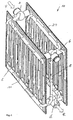
- FIG. 1 is a double-row flat radiator (10) with a flow connection and a return connection and a first flowed through and preferably the space to be heated radiator plate (11) and another flowed through and preferably behind arranged plate (21) and between the heating plates (11, 21) each of the upper side end portion arranged Anschlußgarnituren (a, b) and arranged at the lower side end portions Anschlußgarnituren (c, d) shown.
- connection fittings (a, b, c, d) consist of T-pieces, wherein in the connection fittings (a, c), which are closed to the rear heating plate (21) directed flow directions with locking discs and in the connection fitting (b), the front heating plate (11) directed flow direction is also closed with a locking disc.
- the blocking disks may be provided with a leak opening for venting or emptying the radiator.
- connection fittings (b, d) are connected to each other by a riser pipe (e), with which the flow of heating medium from the front to the rear plate is passed.
- the radiator can be connected to the heating circuit according to the connection diagrams AC, AD, BC, and BD in either direction or on the same side.
- the heating medium supply V can therefore be introduced via the connection set (a) or (b) ( Fig.1 or 2).
- connection fittings (b, d) are connected to each other for guiding the heating medium from the front heating plate (11) in the rear (s) heating plate (21) by a riser (e).
- connection fittings (a, c) opposite the riser (e) In the connection fittings (a, c) opposite the riser (e), the directions of flow directed towards the rear heating plate (s) (21) are closed.
- the lower connecting piece (d) connected to the riser (e) separates the heating medium emerging from the rear plate (21) into the return port (R) from the front plate (11) via the riser (e) into the rear plate (11). 21) to be forwarded heating medium.
- the passage to the rear plate (21) is blocked by a locking disk.
- connection diagram BD the upper connection fitting b comprising the flow connection separates the heating medium flow (V) from the heating medium to be forwarded from the riser pipe (e) to the rear plate (21).
Landscapes
- Engineering & Computer Science (AREA)
- Physics & Mathematics (AREA)
- Thermal Sciences (AREA)
- Chemical & Material Sciences (AREA)
- Combustion & Propulsion (AREA)
- Mechanical Engineering (AREA)
- General Engineering & Computer Science (AREA)
- Domestic Hot-Water Supply Systems And Details Of Heating Systems (AREA)
- Steam Or Hot-Water Central Heating Systems (AREA)
Description
- Die Erfindung betrifft einen mehrreihigen Heizkörper, insbesondere einen Flachheizkörper oder eine Heizwand 1, mit Teillastfunktion.
- Heizkörper mit Einrichtungen zur gerichteten Führung des Heizmediums zur Erreichung einer Teillastfunktion sind bereits bekannt. Dadurch soll erreicht werden, dass beim Heizvorgang bevorzugt die in den zu beheizenden Raum gerichtete Heizplatte mit dem Heizmedium durchströmt wird und so eine schnell fühlbare Erwärmung erfolgt. Derartige Heizkörper können dabei auf verschiedene Weisen dargestellt werden. Eine der Möglichkeiten ist die serielle Schaltung der einzelnen Heizplatten in der Art, dass die dem Raum zugewandte platte zuerst durchströmt wird und die dem Raum abgewandte(n) Platte(n) danach. Ausführungsformen eines solchen Heizkörperprinzips werden im künftigen Renovationsgeschäft eine immer größere Bedeutung bekommen, weshalb besonders Augenmerk auf Varianten ohne integriertes Ventil bei gleichzeitiger völlig frei wählbarer Anschlussbelegung zu legen ist. Derartige Heizkörper werden beispielsweise in der
EP 1 227 290 B1 ,DE 32 16 922 C2 ,DE 20 2004 019 163 U1 ,DE 20 2004 017 628 U1 und der DE-PS 2517611 beschrieben. In derEP 1227 290 B1 wird in einer Ausführungsform in einem der Querkanäle ein Einlegeteil im Bereich eines Vorlaufganges angeordnet, wobei durch das Einlegeteil das Vorlaufwasser zu dem anderen Querkanal leitbar ist. In einer anderen Ausführungsform ist in einem der Querkanäle ein Einlegeteil im Bereich eines Verbindungsstückes angeordnet, wobei durch das Einlegeteil ein Überströmen des Heizwassers aus dem Querkanal in das Verbindungsstück verhindert wird.
In den übrigen Druckschriften sind ähnliche Lösungen mit verschiedenartigen Einlegeteilen beschrieben. Nachteilig bei diesen Lösungen ist, dass vor den Nippeln von Ventil und Absperrverschraubungen die entsprechenden Einlegeteile nach Einbauanleitung in die Anschluss-T-Stücke eingesetzt werden müssen. - Weiter ist aus der
DE 202005012826 U1 bereits eine Armatur bekannt, die sich in Längsrichtung zum Heizkörper selbst erstreckt und die benötigte Schaltung sicherstellt. Nachteilig ist hier die Abhängigkeit von der Baulänge des Heizkörpers. -
EP 0 916 911 A2 zeigt einen mehrreihigen Heizkörper, insbesondere Flachheizkörper oder Heizwand mit einem Vorlaufanschluss und einem Rücklaufanschluss und einer ersten von einem Heizmedium durchströmten und vorzugsweise dem zu beheizenden Raum zugewandten Heizkörperplatte und wenigstens einer weiteren durchströmten und vorzugsweise dahinter angeordneten Platte und zwischen den Heizplatten an einem oberen seitlichen Endabschnitt angeordnete als T-Stück ausgebildete Anschlussgarniture und an einem unteren seitlichen Endabschnitte angeordnete als T-Stück ausgebildete Anschlussgarniture, wobei die Anschlussgarnituren zur Führung des Heizmediums aus der vorderen Heizplatte in die hintere(n) Heizplatte durch ein Steigrohr miteinander verbunden sind, und wobei die untere mit dem Steigrohr verbundene Anschlussgarnitur das aus der hinteren Platte in den Rücklaufanschluss austretende Heizmedium von dem von der vorderen Platte über das Steigrohr in die hintere Platte weiterzuleitende Heizmedium trennt. - Die Aufgabe der vorliegenden Erfindung besteht deshalb darin, dem Anwender einen fertigen und universell anschließbaren in Teillastfunktion betreibbaren Heizkörper bereitzustellen, der sich ohne jeden Bezug auf die Heizkörperbaulänge nur an der Bauhöhe orientiert und damit einfacher und kostengünstiger herstellbar ist. Vorteilhaft können dadurch auch Anschlussfehler ausgeschlossen werden, die die Teillastfunktion beeinträchtigen.
- Erfindungsgemäß wird diese Aufgabe durch die Merkmale des Anspruchs 1 gelöst. In den zugehörigen Ansprüchen 2 bis 7 sind bevorzugte Ausführungen der Erfindung enthalten.
- Demgemäß umfasst die Erfindung einen mehrreihigen Heizkörper, insbesondere Flachheizkörper oder Heizwand mit einem Vorlaufanschluss und einem Rücklaufanschluss und einer ersten von einem Heizmedium durchströmten und vorzugsweise dem zu beheizenden Raum zugewandten Heizkörperplatte und wenigstens einer weiteren durchströmten und vorzugsweise dahinter angeordneten Platte und zwischen den Heizplatten an jedem oberen seitlichen Endabschnitt angeordnete als T- stücke ausgebildete Anschlussgarnituren a, b und an den unteren seitlichen Endabschnitten angeordnete als T- stücke ausgebildete Anschlussgarnituren c, d , wobei die Anschlussgarnituren a, c oder b, d zur Führung des Heizmediums aus der vorderen Heizplatte in die hintere(n) Heizplatte durch ein Steigrohr (e) miteinander verbunden sind. Bei den dem Steigrohr (e) jeweils gegenüberliegenden Anschlussgarnituren sind die zur hinteren Heizplatte(n) gerichteten Strömungsrichtungen verschlossen. Die jeweils unteren mit dem Steigrohr (e) verbundenen Anschlussgarnituren trennen das aus der hinteren Platte in den Rücklaufanschluss (R) austretende Heizmedium von dem von der vorderen Platte über das Steigrohr (e) in die hintere Platte weiterzuleitende Heizmedium. Vorteilhaft ist der Anschluss an den Heizkreislauf nach den Anschlussbildern AC,
- AD, BC, und BD einrichtbar. Der Anschluss des Heizkörpers kann demnach beliebig wechselseitig oder gleichseitig an den Heizkreislauf erfolgen.
- Je nach Anschlussart ist der Heizmedienvorlauf über die rechte oder linke obere Anschlussgarnitur einleitbar. Unerwünschte Strömungsrichtungen in den Anschlussgarnituren werden dadurch verhindert, dass darin Sperrscheiben vorgesehen sind.
- Bei den Anschlussbildern AD, BC ist bei den dem Vorlaufanschluss gegenüberliegenden oberen Anschlussgarnituren der Durchgang zur hinteren Platte durch eine Sperrscheibe versperrt. Die Sperrscheiben können mit Lecköffnungen versehen sein. Die Öffnungen dienen der Entlüftung oder der Entleerung des Heizkörpers.
- Bei den Anschlussbildern AC, BD, trennen die den Vorlaufanschluss umfassenden oberen Anschlussgarnituren den Heizmediumvorlauf (V) von dem aus dem Steigrohr (e) in die hintere Platte weiterzuleitendem Heizmedium. Vorteilhaft kann die Trennung von in Anschlussgarnituren zusammentreffenden Heizmedienströmen durch Doppelrohrausbildungen innerhalb der Anschlussgarnituren erfolgen.
- Nachfolgend wird die Erfindung anhand der in den Zeichnungen dargestellten Figuren näher erläutert. Dabei werden weitere Vorteile der vorliegenden Erfindung offenbart.
- Es zeigen
- Fig.1:
- einen zweireihigen Flachheizkörper in perspektivischer Darstellung mit dem Anschlussbild AD,
- Fig.2:
- ausschnittsweise einen zweireihigen Flachheizkörper in perspektivischer Darstellung mit dem Anschlussbild BD, teilweise geschnitten.
- In der
Figur 1 ist ein zweireihiger Flachheizkörper (10) mit einem Vorlaufanschluss und einem Rücklaufanschluss und einer ersten durchströmten und vorzugsweise dem zu beheizenden Raum zugewandten Heizkörperplatte (11) und einer weiteren durchströmten und vorzugsweise dahinter angeordneten Platte (21) und zwischen den Heizplatten (11, 21) an jedem oberen seitlichen Endabschnitt angeordneten Anschlussgarnituren (a, b) und an den unteren seitlichen Endabschnitten angeordneten Anschlussgarnituren (c, d) dargestellt. - Die Anschlussgarnituren (a, b, c, d) bestehen aus T-Stücken, wobei bei den Anschlussgarnituren (a, c), die zur hinteren Heizplatte (21) gerichteten Strömungsrichtungen mit Sperrscheiben verschlossen sind und bei der Anschlussgarnitur (b), die zur vorderen Heizplatte (11) gerichtete Strömungsrichtung ebenfalls mit einer Sperrscheibe verschlossen ist. Dabei können die Sperrscheiben je nach Anschlussart mit einer Lecköffnung zur Entlüftung oder der Entleerung des Heizkörpers versehen sein.
- Gemäß den
Fig. 1 und2 sind die Anschlussgarnituren (b, d)durch ein Steigrohr (e) miteinander verbunden, mit welchem der Heizmedienstrom von der vorderen zur hinteren Platte geleitet wird. Der Anschluss des Heizkörpers kann beliebig wechselseitig oder gleichseitig an den Heizkreislauf nach den Anschlussbildern AC, AD, BC, und BD erfolgen. Der Heizmedienvorlauf V ist also je nach Anschlussart über die Anschlussgarnitur (a) oder (b) einleitbar (Fig.1 bzw. 2). - Die Anschlussgarnituren (b, d) sind zur Führung des Heizmediums aus der vorderen Heizplatte (11) in die hintere(n) Heizplatte (21) durch ein Steigrohr (e) miteinander verbunden.
- Bei den dem Steigrohr (e) gegenüberliegenden Anschlussgarnituren (a, c) sind die zur hinteren Heizplatte(n) (21) gerichteten Strömungsrichtungen verschlossen.
- Die untere mit dem Steigrohr (e) verbundene Anschlussgarnitur (d) trennt das aus der hinteren Platte (21) in den Rücklaufanschluss (R) austretende Heizmedium von dem von der vorderen Platte (11) über das Steigrohr (e) in die hintere Platte (21) weiterzuleitende Heizmedium. Bei der dem Vorlaufanschluss gegenüberliegenden oberen Anschlussgarnitur b ist der Durchgang zur hinteren Platte (21) durch eine Sperrscheibe versperrt.
- Aus der
Fig. 2 wird deutlich, dass beim Anschlussbild BD, die den Vorlaufanschluss umfassende obere Anschlussgarnitur b den Heizmediumvorlauf (V) von dem aus dem Steigrohr (e) in die hintere Platte (21) weiterzuleitendem Heizmedium trennt.
Claims (7)
- Mehrreihiger Heizkörper, insbesondere Flachheizkörper oder Heizwand (10) mit einem Vorlaufanschluss (V) und einem Rücklaufanschluss (R) und einer ersten von einem Heizmedium durchströmten und vorzugsweise dem zu beheizenden Raum zugewandten Heizkörperplatte (11) und wenigstens einer weiteren durchströmten und vorzugsweise dahinter angeordneten Platte (21) und zwischen den Heizplatten (11, 21) an jedem oberen seitlichen Endabschnitt angeordnete als T-Stücke ausgebildete Anschlussgarnituren (a, b) und an den unteren seitlichen Endabschnitten angeordnete als T-Stücke ausgebildete Anschlussgarnituren (c, d), wobei die Anschlussgarnituren (a, c) oder (b, d) zur Führung des Heizmediums aus der vorderen Heizplatte (11) in die hintere(n) Heizplatte (21) durch ein Steigrohr (e) miteinander verbunden sind,
wobei- bei den dem Steigrohr (e) jeweils gegenüberliegenden Anschlussgarnituren, die zur hinteren Heizplatte(n) (21) gerichteten Strömungsrichtungen verschlossen sind,- die jeweils unteren mit dem Steigrohr (e) verbundenen Anschlussgarnituren das aus der hinteren Platte (21) in den Rücklaufanschluss (R) austretende Heizmedium von dem von der vorderen Platte (11) über das Steigrohr (e) in die hintere Platte (21) weiterzuleitende Heizmedium trennen. - Heizkörper nach Anspruch 1, dadurch gekennzeichnet, dass der Anschluss an den Heizkreislauf nach den Anschlussbildern AC, AD, BC, und BD einrichtbar ist.
- Heizkörper nach den Ansprüchen 1 und 2, dadurch gekennzeichnet, dass der Heizmedienvorlauf (V) je nach Anschlussart über die Anschlussgarnitur (a) oder (b) einleitbar ist.
- Heizkörper nach den Ansprüchen 1 bis 3, dadurch gekennzeichnet, dass bei den Anschlussbildern AD, BC bei den dem Vorlaufanschluss gegenüberliegenden oberen Anschlussgarnituren der Durchgang zur hinteren Platte (21) durch eine Sperrscheibe versperrt ist.
- Heizkörper nach den Ansprüchen 1 bis 3, dadurch gekennzeichnet, dass den Anschlussbildern AC,BD, die den Vorlaufanschluss umfassenden oberen Anschlussgarnituren den Heizmediumvorlauf (V) von dem aus dem Steigrohr (e) in die hintere Platte (21) weiterzuleitendem Heizmedium trennen.
- Heizkörper nach einem der o.g. Ansprüche, dadurch gekennzeichnet, dass die Sperrscheiben zum Verschließen der Anschlussgarnituren (a, b) mit Lecköffnungen versehen sind.
- Heizkörper nach einem der o.g. Ansprüche, dadurch gekennzeichnet, dass die Trennung von in Anschlussgarnituren (a, b) zusammentreffenden Heizmedienströmen durch Doppelrohrausbildungen innerhalb der Anschlussgarnituren erfolgt.
Applications Claiming Priority (2)
| Application Number | Priority Date | Filing Date | Title |
|---|---|---|---|
| DE200720015143 DE202007015143U1 (de) | 2007-10-26 | 2007-10-26 | Heizkörper mit Teillastfunktion |
| PCT/EP2008/002962 WO2009052873A1 (de) | 2007-10-26 | 2008-04-09 | Heizkörper mit teillastfunktion |
Publications (2)
| Publication Number | Publication Date |
|---|---|
| EP2201308A1 EP2201308A1 (de) | 2010-06-30 |
| EP2201308B1 true EP2201308B1 (de) | 2016-08-24 |
Family
ID=38860022
Family Applications (1)
| Application Number | Title | Priority Date | Filing Date |
|---|---|---|---|
| EP08748911.8A Not-in-force EP2201308B1 (de) | 2007-10-26 | 2008-04-09 | Heizkörper mit teillastfunktion |
Country Status (6)
| Country | Link |
|---|---|
| EP (1) | EP2201308B1 (de) |
| CN (1) | CN101796351A (de) |
| DE (1) | DE202007015143U1 (de) |
| PL (1) | PL2201308T3 (de) |
| RU (1) | RU2455581C2 (de) |
| WO (1) | WO2009052873A1 (de) |
Cited By (1)
| Publication number | Priority date | Publication date | Assignee | Title |
|---|---|---|---|---|
| EP4600595A1 (de) * | 2024-02-08 | 2025-08-13 | Commital isi Ekipmanlari Kalip Sanayi Ve Tic. Ltd. Sti | Heizkörper |
Families Citing this family (4)
| Publication number | Priority date | Publication date | Assignee | Title |
|---|---|---|---|---|
| DE202008007454U1 (de) * | 2008-06-04 | 2008-07-31 | Kermi Gmbh | Heizkörper mit Teillastfunktion |
| WO2022060244A1 (ru) * | 2020-09-15 | 2022-03-24 | Фёдор Васильевич ИЛЬИН | Радиатор водяного отопления универсального подключения |
| RU204144U1 (ru) * | 2020-09-15 | 2021-05-11 | Фёдор Васильевич Ильин | Радиатор водяного отопления универсального подключения |
| DE102021203900A1 (de) * | 2021-04-20 | 2022-10-20 | Kermi Gmbh | Ein- oder mehrreihiger Heizkörper |
Family Cites Families (7)
| Publication number | Priority date | Publication date | Assignee | Title |
|---|---|---|---|---|
| DE29511076U1 (de) * | 1995-07-07 | 1995-09-21 | König, Christel, 63674 Altenstadt | Heizkörperanordnung |
| DE19750109C2 (de) * | 1997-11-12 | 2000-09-21 | Kermi Gmbh | Anschlußgarnitur und Heizkörper |
| RU2145691C1 (ru) * | 1999-07-08 | 2000-02-20 | Зелиско Павел Михайлович | Отопительный конвектор |
| DE20101345U1 (de) * | 2001-01-25 | 2001-03-29 | König, Christel, 63674 Altenstadt | Heizkörperanordnung |
| DE20102602U1 (de) * | 2001-02-11 | 2002-03-21 | Pause, Jan-Peter, 21075 Hamburg | Mehrlagiger Plattenheizkörper |
| RU19150U1 (ru) * | 2001-02-20 | 2001-08-10 | Открытое акционерное общество "Механический завод" | Радиатор водяного отопления |
| DE202005012826U1 (de) * | 2005-08-09 | 2005-10-20 | Kermi Gmbh | Heizkörper mit Teillastfunktion |
-
2007
- 2007-10-26 DE DE200720015143 patent/DE202007015143U1/de not_active Expired - Lifetime
-
2008
- 2008-04-09 RU RU2010120797/06A patent/RU2455581C2/ru not_active IP Right Cessation
- 2008-04-09 CN CN200880105555A patent/CN101796351A/zh active Pending
- 2008-04-09 WO PCT/EP2008/002962 patent/WO2009052873A1/de not_active Ceased
- 2008-04-09 PL PL08748911T patent/PL2201308T3/pl unknown
- 2008-04-09 EP EP08748911.8A patent/EP2201308B1/de not_active Not-in-force
Cited By (1)
| Publication number | Priority date | Publication date | Assignee | Title |
|---|---|---|---|---|
| EP4600595A1 (de) * | 2024-02-08 | 2025-08-13 | Commital isi Ekipmanlari Kalip Sanayi Ve Tic. Ltd. Sti | Heizkörper |
Also Published As
| Publication number | Publication date |
|---|---|
| PL2201308T3 (pl) | 2017-02-28 |
| CN101796351A (zh) | 2010-08-04 |
| RU2010120797A (ru) | 2011-12-10 |
| WO2009052873A1 (de) | 2009-04-30 |
| DE202007015143U1 (de) | 2007-12-27 |
| RU2455581C2 (ru) | 2012-07-10 |
| EP2201308A1 (de) | 2010-06-30 |
Similar Documents
| Publication | Publication Date | Title |
|---|---|---|
| EP2201308B1 (de) | Heizkörper mit teillastfunktion | |
| EP2131118B1 (de) | Heizkörper mit Teillastfunktion | |
| EP2023057B1 (de) | Vorschaltgarnitur für Heizkörper | |
| EP1752719B1 (de) | Heizkörper mit Teillastfunktion | |
| EP1418387A1 (de) | Kompaktheizungsanlage mit zwei Heizkreisen | |
| EP2171365B1 (de) | Heizkörper mit teillastfunktion | |
| EP2171366A1 (de) | Heizkörper mit teillastfunktion | |
| DE102005061297B4 (de) | Kugelventil | |
| DE10223790B4 (de) | Plattenheizkörper | |
| DE102007002340B3 (de) | Hochdruckwärmetauscher | |
| EP1669691B1 (de) | Mehrreihiger Heizkörper, insbesondere Flachheizkörper | |
| EP2479510A2 (de) | Ventilgarnitur sowie Heizkörper mit einer solchen | |
| DE3120396A1 (de) | "thermostatische ventilgarnitur mit einer umstelleinrichtung zur verwendung in einrohr- und zweirohrheizungsanlagen" | |
| DE69520441T2 (de) | Plattenwärmetauscher | |
| DE102006031406A1 (de) | Heizkörper, insbesondere Röhrenradiator | |
| DE10215844B4 (de) | System zum universellen Anschluss eines Heizkörpers | |
| EP2136153B1 (de) | Flachheizkörper | |
| DE102021203900A1 (de) | Ein- oder mehrreihiger Heizkörper | |
| AT411293B (de) | Heiz-(kühl-)körper | |
| EP2824399B1 (de) | Anschlussteil, Heizkörper und Verfahren zum Anschluss eines Heizkörpers | |
| DE102009003193A1 (de) | Verfahren zum Entlüften eines Plattenheizkörpers und Plattenheizkörper | |
| DE102017001992A1 (de) | Heizkörper und zugehöriges Heizkörperventil | |
| DE20021519U1 (de) | Heizkörper mit einer mittig angeordneten Verteilergarnitur | |
| WO2009015629A2 (de) | Röhrenradiator | |
| DE10113125A1 (de) | Heizkörper mit einer mittig angeordneten Ventilgarnitur |
Legal Events
| Date | Code | Title | Description |
|---|---|---|---|
| PUAI | Public reference made under article 153(3) epc to a published international application that has entered the european phase |
Free format text: ORIGINAL CODE: 0009012 |
|
| 17P | Request for examination filed |
Effective date: 20100120 |
|
| AK | Designated contracting states |
Kind code of ref document: A1 Designated state(s): AT BE BG CH CY CZ DE DK EE ES FI FR GB GR HR HU IE IS IT LI LT LU LV MC MT NL NO PL PT RO SE SI SK TR |
|
| AX | Request for extension of the european patent |
Extension state: AL BA MK RS |
|
| DAX | Request for extension of the european patent (deleted) | ||
| REG | Reference to a national code |
Ref country code: DE Ref legal event code: R079 Ref document number: 502008014558 Country of ref document: DE Free format text: PREVIOUS MAIN CLASS: F24H0009120000 Ipc: F24D0019000000 |
|
| RIC1 | Information provided on ipc code assigned before grant |
Ipc: F24D 19/00 20060101AFI20151218BHEP |
|
| GRAP | Despatch of communication of intention to grant a patent |
Free format text: ORIGINAL CODE: EPIDOSNIGR1 |
|
| INTG | Intention to grant announced |
Effective date: 20160404 |
|
| GRAS | Grant fee paid |
Free format text: ORIGINAL CODE: EPIDOSNIGR3 |
|
| GRAA | (expected) grant |
Free format text: ORIGINAL CODE: 0009210 |
|
| AK | Designated contracting states |
Kind code of ref document: B1 Designated state(s): AT BE BG CH CY CZ DE DK EE ES FI FR GB GR HR HU IE IS IT LI LT LU LV MC MT NL NO PL PT RO SE SI SK TR |
|
| REG | Reference to a national code |
Ref country code: GB Ref legal event code: FG4D Free format text: NOT ENGLISH |
|
| REG | Reference to a national code |
Ref country code: CH Ref legal event code: EP |
|
| REG | Reference to a national code |
Ref country code: AT Ref legal event code: REF Ref document number: 823461 Country of ref document: AT Kind code of ref document: T Effective date: 20160915 |
|
| REG | Reference to a national code |
Ref country code: IE Ref legal event code: FG4D Free format text: LANGUAGE OF EP DOCUMENT: GERMAN |
|
| REG | Reference to a national code |
Ref country code: DE Ref legal event code: R096 Ref document number: 502008014558 Country of ref document: DE |
|
| REG | Reference to a national code |
Ref country code: CH Ref legal event code: NV Representative=s name: GACHNANG AG PATENTANWAELTE, CH |
|
| REG | Reference to a national code |
Ref country code: NL Ref legal event code: FP |
|
| REG | Reference to a national code |
Ref country code: LT Ref legal event code: MG4D |
|
| PG25 | Lapsed in a contracting state [announced via postgrant information from national office to epo] |
Ref country code: NO Free format text: LAPSE BECAUSE OF FAILURE TO SUBMIT A TRANSLATION OF THE DESCRIPTION OR TO PAY THE FEE WITHIN THE PRESCRIBED TIME-LIMIT Effective date: 20161124 Ref country code: IT Free format text: LAPSE BECAUSE OF FAILURE TO SUBMIT A TRANSLATION OF THE DESCRIPTION OR TO PAY THE FEE WITHIN THE PRESCRIBED TIME-LIMIT Effective date: 20160824 Ref country code: HR Free format text: LAPSE BECAUSE OF FAILURE TO SUBMIT A TRANSLATION OF THE DESCRIPTION OR TO PAY THE FEE WITHIN THE PRESCRIBED TIME-LIMIT Effective date: 20160824 Ref country code: LT Free format text: LAPSE BECAUSE OF FAILURE TO SUBMIT A TRANSLATION OF THE DESCRIPTION OR TO PAY THE FEE WITHIN THE PRESCRIBED TIME-LIMIT Effective date: 20160824 |
|
| REG | Reference to a national code |
Ref country code: SK Ref legal event code: T3 Ref document number: E 22345 Country of ref document: SK |
|
| PG25 | Lapsed in a contracting state [announced via postgrant information from national office to epo] |
Ref country code: ES Free format text: LAPSE BECAUSE OF FAILURE TO SUBMIT A TRANSLATION OF THE DESCRIPTION OR TO PAY THE FEE WITHIN THE PRESCRIBED TIME-LIMIT Effective date: 20160824 Ref country code: LV Free format text: LAPSE BECAUSE OF FAILURE TO SUBMIT A TRANSLATION OF THE DESCRIPTION OR TO PAY THE FEE WITHIN THE PRESCRIBED TIME-LIMIT Effective date: 20160824 Ref country code: GR Free format text: LAPSE BECAUSE OF FAILURE TO SUBMIT A TRANSLATION OF THE DESCRIPTION OR TO PAY THE FEE WITHIN THE PRESCRIBED TIME-LIMIT Effective date: 20161125 Ref country code: PT Free format text: LAPSE BECAUSE OF FAILURE TO SUBMIT A TRANSLATION OF THE DESCRIPTION OR TO PAY THE FEE WITHIN THE PRESCRIBED TIME-LIMIT Effective date: 20161226 Ref country code: SE Free format text: LAPSE BECAUSE OF FAILURE TO SUBMIT A TRANSLATION OF THE DESCRIPTION OR TO PAY THE FEE WITHIN THE PRESCRIBED TIME-LIMIT Effective date: 20160824 |
|
| REG | Reference to a national code |
Ref country code: FR Ref legal event code: PLFP Year of fee payment: 10 |
|
| PG25 | Lapsed in a contracting state [announced via postgrant information from national office to epo] |
Ref country code: EE Free format text: LAPSE BECAUSE OF FAILURE TO SUBMIT A TRANSLATION OF THE DESCRIPTION OR TO PAY THE FEE WITHIN THE PRESCRIBED TIME-LIMIT Effective date: 20160824 Ref country code: RO Free format text: LAPSE BECAUSE OF FAILURE TO SUBMIT A TRANSLATION OF THE DESCRIPTION OR TO PAY THE FEE WITHIN THE PRESCRIBED TIME-LIMIT Effective date: 20160824 |
|
| REG | Reference to a national code |
Ref country code: DE Ref legal event code: R097 Ref document number: 502008014558 Country of ref document: DE |
|
| PG25 | Lapsed in a contracting state [announced via postgrant information from national office to epo] |
Ref country code: BG Free format text: LAPSE BECAUSE OF FAILURE TO SUBMIT A TRANSLATION OF THE DESCRIPTION OR TO PAY THE FEE WITHIN THE PRESCRIBED TIME-LIMIT Effective date: 20161124 Ref country code: DK Free format text: LAPSE BECAUSE OF FAILURE TO SUBMIT A TRANSLATION OF THE DESCRIPTION OR TO PAY THE FEE WITHIN THE PRESCRIBED TIME-LIMIT Effective date: 20160824 |
|
| PGFP | Annual fee paid to national office [announced via postgrant information from national office to epo] |
Ref country code: PL Payment date: 20170323 Year of fee payment: 10 |
|
| PGFP | Annual fee paid to national office [announced via postgrant information from national office to epo] |
Ref country code: NL Payment date: 20170419 Year of fee payment: 10 Ref country code: TR Payment date: 20170328 Year of fee payment: 10 |
|
| PLBE | No opposition filed within time limit |
Free format text: ORIGINAL CODE: 0009261 |
|
| STAA | Information on the status of an ep patent application or granted ep patent |
Free format text: STATUS: NO OPPOSITION FILED WITHIN TIME LIMIT |
|
| PGFP | Annual fee paid to national office [announced via postgrant information from national office to epo] |
Ref country code: GB Payment date: 20170419 Year of fee payment: 10 Ref country code: DE Payment date: 20170314 Year of fee payment: 10 Ref country code: CZ Payment date: 20170407 Year of fee payment: 10 Ref country code: CH Payment date: 20170419 Year of fee payment: 10 Ref country code: FR Payment date: 20170419 Year of fee payment: 10 Ref country code: SK Payment date: 20170407 Year of fee payment: 10 |
|
| 26N | No opposition filed |
Effective date: 20170526 |
|
| PG25 | Lapsed in a contracting state [announced via postgrant information from national office to epo] |
Ref country code: SI Free format text: LAPSE BECAUSE OF FAILURE TO SUBMIT A TRANSLATION OF THE DESCRIPTION OR TO PAY THE FEE WITHIN THE PRESCRIBED TIME-LIMIT Effective date: 20160824 |
|
| PGFP | Annual fee paid to national office [announced via postgrant information from national office to epo] |
Ref country code: FI Payment date: 20170412 Year of fee payment: 10 Ref country code: BE Payment date: 20170419 Year of fee payment: 10 Ref country code: AT Payment date: 20170420 Year of fee payment: 10 |
|
| REG | Reference to a national code |
Ref country code: IE Ref legal event code: MM4A |
|
| PG25 | Lapsed in a contracting state [announced via postgrant information from national office to epo] |
Ref country code: MC Free format text: LAPSE BECAUSE OF FAILURE TO SUBMIT A TRANSLATION OF THE DESCRIPTION OR TO PAY THE FEE WITHIN THE PRESCRIBED TIME-LIMIT Effective date: 20160824 |
|
| PG25 | Lapsed in a contracting state [announced via postgrant information from national office to epo] |
Ref country code: LU Free format text: LAPSE BECAUSE OF NON-PAYMENT OF DUE FEES Effective date: 20170409 |
|
| PG25 | Lapsed in a contracting state [announced via postgrant information from national office to epo] |
Ref country code: IE Free format text: LAPSE BECAUSE OF NON-PAYMENT OF DUE FEES Effective date: 20170409 |
|
| PG25 | Lapsed in a contracting state [announced via postgrant information from national office to epo] |
Ref country code: MT Free format text: LAPSE BECAUSE OF FAILURE TO SUBMIT A TRANSLATION OF THE DESCRIPTION OR TO PAY THE FEE WITHIN THE PRESCRIBED TIME-LIMIT Effective date: 20160824 |
|
| REG | Reference to a national code |
Ref country code: DE Ref legal event code: R119 Ref document number: 502008014558 Country of ref document: DE |
|
| PG25 | Lapsed in a contracting state [announced via postgrant information from national office to epo] |
Ref country code: CZ Free format text: LAPSE BECAUSE OF NON-PAYMENT OF DUE FEES Effective date: 20180409 |
|
| REG | Reference to a national code |
Ref country code: CH Ref legal event code: PL |
|
| REG | Reference to a national code |
Ref country code: NL Ref legal event code: MM Effective date: 20180501 |
|
| REG | Reference to a national code |
Ref country code: AT Ref legal event code: MM01 Ref document number: 823461 Country of ref document: AT Kind code of ref document: T Effective date: 20180409 |
|
| REG | Reference to a national code |
Ref country code: BE Ref legal event code: MM Effective date: 20180430 |
|
| GBPC | Gb: european patent ceased through non-payment of renewal fee |
Effective date: 20180409 |
|
| REG | Reference to a national code |
Ref country code: SK Ref legal event code: MM4A Ref document number: E 22345 Country of ref document: SK Effective date: 20180409 |
|
| PG25 | Lapsed in a contracting state [announced via postgrant information from national office to epo] |
Ref country code: SK Free format text: LAPSE BECAUSE OF NON-PAYMENT OF DUE FEES Effective date: 20180409 Ref country code: DE Free format text: LAPSE BECAUSE OF NON-PAYMENT OF DUE FEES Effective date: 20181101 Ref country code: NL Free format text: LAPSE BECAUSE OF NON-PAYMENT OF DUE FEES Effective date: 20180501 Ref country code: FI Free format text: LAPSE BECAUSE OF NON-PAYMENT OF DUE FEES Effective date: 20180409 Ref country code: AT Free format text: LAPSE BECAUSE OF NON-PAYMENT OF DUE FEES Effective date: 20180409 |
|
| PG25 | Lapsed in a contracting state [announced via postgrant information from national office to epo] |
Ref country code: GB Free format text: LAPSE BECAUSE OF NON-PAYMENT OF DUE FEES Effective date: 20180409 Ref country code: CH Free format text: LAPSE BECAUSE OF NON-PAYMENT OF DUE FEES Effective date: 20180430 Ref country code: LI Free format text: LAPSE BECAUSE OF NON-PAYMENT OF DUE FEES Effective date: 20180430 Ref country code: BE Free format text: LAPSE BECAUSE OF NON-PAYMENT OF DUE FEES Effective date: 20180430 |
|
| PG25 | Lapsed in a contracting state [announced via postgrant information from national office to epo] |
Ref country code: FR Free format text: LAPSE BECAUSE OF NON-PAYMENT OF DUE FEES Effective date: 20180430 |
|
| PG25 | Lapsed in a contracting state [announced via postgrant information from national office to epo] |
Ref country code: HU Free format text: LAPSE BECAUSE OF FAILURE TO SUBMIT A TRANSLATION OF THE DESCRIPTION OR TO PAY THE FEE WITHIN THE PRESCRIBED TIME-LIMIT; INVALID AB INITIO Effective date: 20080409 |
|
| PG25 | Lapsed in a contracting state [announced via postgrant information from national office to epo] |
Ref country code: CY Free format text: LAPSE BECAUSE OF NON-PAYMENT OF DUE FEES Effective date: 20160824 |
|
| PG25 | Lapsed in a contracting state [announced via postgrant information from national office to epo] |
Ref country code: PL Free format text: LAPSE BECAUSE OF NON-PAYMENT OF DUE FEES Effective date: 20180409 |
|
| PG25 | Lapsed in a contracting state [announced via postgrant information from national office to epo] |
Ref country code: IS Free format text: LAPSE BECAUSE OF FAILURE TO SUBMIT A TRANSLATION OF THE DESCRIPTION OR TO PAY THE FEE WITHIN THE PRESCRIBED TIME-LIMIT Effective date: 20161224 |
|
| PG25 | Lapsed in a contracting state [announced via postgrant information from national office to epo] |
Ref country code: TR Free format text: LAPSE BECAUSE OF NON-PAYMENT OF DUE FEES Effective date: 20180409 |