EP2201762B1 - Konfigurierung von videokonferenzsystemen zur herstellung von videositzungen mit realistischer präsenz - Google Patents
Konfigurierung von videokonferenzsystemen zur herstellung von videositzungen mit realistischer präsenz Download PDFInfo
- Publication number
- EP2201762B1 EP2201762B1 EP08837376.6A EP08837376A EP2201762B1 EP 2201762 B1 EP2201762 B1 EP 2201762B1 EP 08837376 A EP08837376 A EP 08837376A EP 2201762 B1 EP2201762 B1 EP 2201762B1
- Authority
- EP
- European Patent Office
- Prior art keywords
- far
- video
- videoconferencing system
- configuration information
- cameras
- Prior art date
- Legal status (The legal status is an assumption and is not a legal conclusion. Google has not performed a legal analysis and makes no representation as to the accuracy of the status listed.)
- Active
Links
Images


Classifications
-
- H—ELECTRICITY
- H04—ELECTRIC COMMUNICATION TECHNIQUE
- H04N—PICTORIAL COMMUNICATION, e.g. TELEVISION
- H04N7/00—Television systems
- H04N7/14—Systems for two-way working
- H04N7/141—Systems for two-way working between two video terminals, e.g. videophone
- H04N7/142—Constructional details of the terminal equipment, e.g. arrangements of the camera and the display
-
- H—ELECTRICITY
- H04—ELECTRIC COMMUNICATION TECHNIQUE
- H04N—PICTORIAL COMMUNICATION, e.g. TELEVISION
- H04N7/00—Television systems
- H04N7/14—Systems for two-way working
- H04N7/141—Systems for two-way working between two video terminals, e.g. videophone
- H04N7/148—Interfacing a video terminal to a particular transmission medium, e.g. ISDN
-
- H—ELECTRICITY
- H04—ELECTRIC COMMUNICATION TECHNIQUE
- H04N—PICTORIAL COMMUNICATION, e.g. TELEVISION
- H04N7/00—Television systems
- H04N7/14—Systems for two-way working
- H04N7/15—Conference systems
Definitions
- the subject matter of the present disclosure relates to systems and methods for configuring videoconferencing systems by exchanging information between videoconferencing systems to create a videoconferencing session with a realistic presence.
- Videoconferencing systems are increasingly being used to conduct meetings when not all participants are present at the same location.
- a user of a near-end videoconferencing system manually selects presets for the near-end system (e.g., selects the number or type of video displays) and manually adjusts one or more video cameras at the near-end system to interface with a far-end videoconferencing system.
- Manual configuration becomes increasingly difficult for users because the users must account for different features (i.e., the number of displays and corresponding monitors, the aspect ratio of each display, etc.) in different systems intended to interface with each other.
- European Patent Application EP 1 601 196 A1 discloses a system and method for preparing video communication images for wide screen displays.
- An endpoint has a wide screen display.
- the disclosed system creates an image with an aspect ratio of about 16:9 for the endpoint.
- the image is altered or modified to change aspect ratio to about 4:3.
- two portions can be added to the image to increase the overall height of the image.
- the wide screen display is set to a zoom mode and is capable of substantially displaying the image without the added portions.
- the image is stretched along its height by a factor or 4/3.
- the wide screen display is set to the wide screen mode and is capable of substantially displaying the image without the stretched height.
- the system and method can receive signals that the endpoint has a wide screen display and can also inform a user at the endpoint to set the wide screen display to the wide or zoom modes.
- a configuration process automates the configuration between different videoconferencing systems that have different configurations for handling (displaying and capturing) video for a videoconference session.
- the two systems exchange their configuration information indicative of the video handling capabilities of the systems.
- This configuration information can include the video capturing capabilities of the system, such as the number and position of cameras useable for capturing video, the aspect ratio used by the system for capturing video, and the field of view of the cameras ( e.g., pan/tilt/zoom orientation of the cameras).
- the configuration information can also include video displaying capabilities of the system, such as the number and position of displays at the system available for displaying video and the aspect ratio used by the system for displaying video.
- the configuration information can be exchanged in detail, or the two systems can exchange an identification or some other indicia that the other system can then use to determine the system's configuration using a cross-reference look-up or the like.
- each system uses the other system's information to set up custom camera and/or display settings to accommodate the other system's configuration. In this way, the two videoconferencing systems can create videoconferencing sessions that offer a realistic presence for participants without the need to manually adjust settings to get an acceptable configuration.
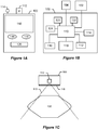
- a representative videoconferencing system 100 shown in FIG. 1A has a video camera 112, a microphone 114, speakers 116, a video display 118, and a control interface 120. While each of these components is shown in a particular physical configuration, the exact number, position, and capabilities of each of these components may vary, as will be discussed in detail below. Further, other components not shown in FIG. 1A may also be present in the videoconferencing system 100.
- the videoconferencing system 100 representing a near-end system can connect to one or more far-end videoconferencing systems 104. Additionally, the near-end system 100 can connect to one or more local videoconferencing systems 102.
- the videoconferencing system 100 includes a control unit 110 to handle control and input/output (I/O) functions of the system 100.
- the control unit 110 can be, for example, a dedicated microprocessor system, or other combinations of hardware and/or software configured to control functions of the local videoconferencing system 100.
- the control unit 110 connects to the video camera 112, microphone 114, speaker 116, video display 118, user interface (e.g., control panel) 120, status display 122, and a compression/decompression unit (codec) 124.
- codec compression/decompression unit
- the near-end videoconferencing system 100 is shown connected to one local system 102, any number of such local systems may be connected to the near-end system 100.
- the near-end system 100 may serve as a master system to the other local systems 102 so it can control some of the functionality of the other systems 102.
- the codec 124 may serve as a primary codec for the combined systems 100, 102.
- the near-end system 100 communicates with the far-end system 104 using protocols well-known in the art, including H.224, H.225, H.281, H.261, H.263, H.320, H.323, etc.
- the near-end videoconferencing system 100 communicates configuration information to the far-end videoconferencing system 104 using a known signalling protocol (e.g., H.225).
- a known signalling protocol e.g., H.225
- the near-end system 100 can receive configuration information in a similar way from the far-end system 104.
- the configuration information exchanged between systems 100 and 104 is indicative of the video handling (displaying and capturing) capabilities or physical makeup of components available at the system.
- the configuration information describes the physical configuration or processing capabilities of the given system for displaying and capturing video signals for a videoconference session.
- the configuration information can include how many video displays are available locally, the aspect ratio of the local video displays, the number and position of the local video cameras, the aspect ratio of the local video cameras and displays, etc.
- the configuration information may be an identification or other such identifier of the system sending the information.
- the identification can be a model number or other dataset that identifies the model of the system.
- the primary codec in each system 100/104 can append such an identification (indicative of features such as aspect ratios of video displays and video cameras, and the numbers of displays and cameras available) to the software version string that is sent via the H.225 setup message to the other system.
- the systems 100/104 can use the identifications as indications of the configuration of the other system.
- a calling system e.g., 100
- the far-end system e.g., 104
- the systems 100 and 104 can use a cross-reference lookup in memory to determine the configuration of the other system. In this way, the configuration information may be sent as part of the setup message or as part of the connect message during setup of a videoconferencing session.
- the near-end videoconferencing system (e.g., 100) automatically adjusts its video camera(s) 112 so that the video signals that the system 100 captures and sends corresponds to the available video display(s) on the far-end system 104 receiving the video signal.
- Adjustment of the video cameras 112 may include several aspects.
- the near-end system 100 may automatically select some number of video cameras 112 to capture video out of a total number of available cameras. The selected number of cameras 112 may vary depending upon the capabilities of the far-end system 104, which will be discussed in further detail below.
- the near-end system 100 may automatically select pan, tilt, and zoom settings for each camera 112 used to capture video signals. Optimally, these settings correspond to the video display capabilities of the far-end system 104.
- the videoconferencing system 100 having the video camera 112 and the video display 118 is positioned relative to a table 130 in front of the system 100.
- the field of view 113 of the video camera 112 may be adjusted by changing the pan, tilt, and/or zoom of the video camera 112, as mentioned briefly above.
- the field of view 113 of the camera 112 may be zoomed in to focus on a particular area or person, or zoomed out to encompass a larger area.
- the camera 112 may be tilted up and down to emphasize different portions of the available field of view.
- the camera 112 may be panned from left to right to move the side boundaries of the available field of view. All of these functions can be performed by the videoconferencing system 100 based on configuration information from a far-end system (104).
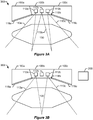
- a videoconferencing system 200 has two videoconferencing components (100a-b)-both of which can be similar to the videoconferencing system 100 discussed above. As such, the system 200 has, among other elements, two video cameras 112a-b and two video displays 118a-b.
- the two video cameras 112a-b are typically positioned such that each camera 112a-b has a different field of view 113a-b, allowing each camera 112a-b to capture video signals of different areas.
- the combination of the different captured video signals seamlessly encompasses a desired area to be broadcast to a far-end videoconferencing system.
- the videoconferencing system 200 receives far-end video signals for display on its video displays 118a-b, local codecs (not shown) interpret the far-end video signals and display the video signals on the displays 118a-b.
- the video captured by cameras at the far-end corresponds to a single, seamless image of a desired field of view
- the video displays 118a-b at the near-end system 200 display the video so that the single, seamless image appears on the video displays 118a-b.
- the first camera 112a does not capture a video image for sending to the far-end
- the second camera 112b has a field of view 113 that encompasses all of the table 130.
- Such a setting may be desirable when the videoconference system 200 sends a video signal to a far-end system having only a single display, as with the system 100 of FIG. 1C .
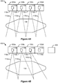
- a videoconferencing system 300 has three videoconferencing components 100a-c-each of which is similar to the videoconferencing system 100 discussed above-and has, among other elements, three video cameras 112a-c and three video displays 118a-c. Similar to the discussion of FIGS. 2A-2B , the fields of view 113 of the cameras 112a-c may be changed depending on the configuration of the far-end system used in a videoconferencing session.
- all three cameras 112a-c may be used to broadcast one-third of the desired field of view.
- the system 300 communicates with another far-end system having a different number of cameras and/or displays, the settings may be changed.
- the cameras 112a and 112c may not be used when the near-end system 300 communicates with a far-end system having only a single video display ( e.g., the system 100 of FIG. 1C ).
- the settings of the middle camera 112b may be adjusted so that its field of view 113b encompasses the entire table 130.
- the middle video camera 112b may not be used. Instead, the outer cameras 112a, 112c may be used, and the fields of view 113a, 113c may be adjusted to encompass the entire table 130. In other words, the settings of the cameras 112a, 112b are adjusted for optimal display on the video displays of the two-display system (200).
- a videoconferencing system 400 has four videoconferencing components 100a-d each of which can be similar to the videoconferencing system 100 discussed above and has, among other elements, four video cameras 112a-d and four video displays 118a-d. It should be apparent after the discussions of the previous systems that the use of the cameras 112a-d may be adjusted depending on the number of cameras available locally and the number of displays available in a connected far-end videoconferencing system.
- the fields of views 113a-d of the cameras 112a-d are set up such that each field of view 113a-d encompasses a potion of the desired area of the room, table 130, etc.
- the fields of views 113a-d of the cameras 112a-d are set up such that each field of view 113a-d encompasses a potion of the desired area of the room, table 130, etc.
- only two displays are available on a far-end system (e.g., as with system 200 in FIG 2A )
- only cameras 112b and 112c may be used, while cameras 112a and 112d are not.
- the choice of these two cameras 112b and 112c may be preferable due to the fact that these cameras are more centrally located and thus offer a wider fields of view 113b, 113c, with less distortion than that of cameras 112a or 112d.
- FIG. 4B when the videoconferencing system 400 communicates with a far-end videoconferencing system having three displays (e.g., as with the system 300 in FIGS. 3A-3B ), only three of the available four video cameras 112a-d are used, and the settings of these cameras 112a-d are adjusted for optimal display on the video displays of the three-display system (300).
- Other configurations of the cameras 112a-d are of course possible, depending on particular constraints defined by, for example, the size and geometry of the arrangement, the size and geometry of furniture in the surrounding room (e.g., table 130) the number of people present, and other factors.
- mapping of the video signals may be performed automatically based on aspect ratio signalling (e.g., using the H.241 videoconferencing standard) and signalling of the videoconferencing system type (e.g., by the version string in the H.225 videoconferencing standard) discussed previously.
- each video display 118a-b has an aspect ratio of 4:3 and displays video data received from another system.
- the video data is received from two of the video cameras of a far-end, three-camera system (e.g., cameras 112a and 112c of the system 300 in FIG. 3B ).
- Each of the far-end cameras may have a 16:9 aspect ratio.
- each video display 118a-b displays the appropriate video data using a letterbox effect similar to that used to display wide-angle video images in conventional 4:3 aspect ratio displays. In other words, a portion of the top and the bottom of each display 118a-b is not used. In this manner, the video from the far-end system appears as a single seamless image on the displays 118a-b.
- each video display 118a-b receives video data from another system.
- the video is received from two of the video cameras of a four-camera system (e.g., cameras 112b and 112c of the system 400 in FIG. 4A ).
- Each far-end camera (112b, 112c) may have the same 4:3 aspect ratio as the video displays 118a-b. Accordingly, each video display 118a-b displays the video data as it is sent from the far-end system using the same aspect ratio.
- a single video camera e.g., camera 112 from a one-monitor videoconferencing system (e.g., system 100 in FIG. 1C ) is used to send data to the exemplary two display system 200 having displays 118a-b
- only one of the video displays e.g., 118a
- the other e.g., 118b
- the letterbox effect could also be used in such a situation if the far-end camera from the one-monitor videoconferencing system (100) captures data in a wide-angle format.
- three video displays 118a-c for a three-display system 300 as in FIGS. 3A-3B can have a wide (16:9) aspect ratio and may be used to receive video signals from various videoconferencing systems.
- two video displays 118a-b each of which have an aspect ratio of 16:9, receive video signals from another system, where the video cameras have a 4:3 aspect ratio.
- the other system may be, for example, the two-camera videoconferencing system 200 shown in FIG. 2A .
- the third video display 118c of the videoconferencing system is not used when receiving video from such a far-end two-camera system.
- a single video display e.g., 118b
- the central display 118b may be used as preferred because of its central location. This selection can be made based on the configuration information exchanged, which can include the position of displays for a system.
- a common "pillaring" effect cannot be used to display the signals on the video displays.
- a pillaring effect implies that the side ends of the wide display (118a-b) are not used to display the video signal having a narrower aspect ratio. If such a pillaring effect were used in this case, there would be a gap between the two images in the displays 118a-b (i.e., a large portion at the interface of the two displays with no video data), which would result in a loss of a seamless videoconferencing image.
- the video cameras 112a-b of the far-end system that send video data to the video displays 118a-b are adjusted (e.g., using pan, tilt, and zoom, as described above) so that each video display 118-b displays the appropriate video data when a portion of the top and bottom of the signals sent from the video cameras 112a-b are cut off for display in each video display 118a-b.
- the video cameras 112a-b ideally, are adjusted so that the portion of the 4:3 signal that is not used would not encompass people or other features in the far conference room that would be desired to be viewed.
- the top and bottom portions of the 4:3 video signal are cropped asymmetrically (e.g., more of the top is cropped than of the bottom), due to the room arrangement at the far-end.
- FIG. 6B shows how the exemplary video displays 118a-c may be used to receive video signals from a videoconferencing system having more video cameras than available video displays.
- the far system is a four-camera system (e.g., system 400 shown in FIG. 4B ), which has already been configured to send video signals from only three of its available four video cameras.
- all three of the video displays 118a-c are used to display one-third of the far-end conference site, using video signals sent from the video cameras 112a-c. Similar to the interface to the two-camera system shown in FIG.
- the tops and bottoms of the received video signals from the video cameras 112a-c are cropped such that a portion of the top and a portion of the bottom of the signals are removed, resulting in a seamless image across the three video displays 118a-c.
- a single video signal from a single-camera system may be displayed on one video display (e.g., 118b).
- the above-discussed cropping is not necessary.
- FIGS. 7A-7B show how an exemplary four-monitor video display 118a-d having a normal (4:3) aspect ratio (i.e., from the videoconferencing components 100a-d shown in FIG. 4A-4B ) may be used to receive video signals from various videoconferencing systems.
- a normal (4:3) aspect ratio i.e., from the videoconferencing components 100a-d shown in FIG. 4A-4B
- FIGS. 7A-7B show how an exemplary four-monitor video display 118a-d having a normal (4:3) aspect ratio (i.e., from the videoconferencing components 100a-d shown in FIG. 4A-4B ) may be used to receive video signals from various videoconferencing systems.
- FIG. 7A shows how an exemplary four-monitor video display 118a-d having a normal (4:3) aspect ratio (i.e., from the videoconferencing components 100a-d shown in FIG. 4A-4B ) may be used to receive video signals from various videoconferencing systems.
- FIG. 7A shows
- the near-end system uses a letterbox effect to display the far-end video signals.
- FIG. 7B When even fewer far-end video cameras are used, fewer corresponding near-end video displays are also used, as is shown in FIG. 7B .
- a two-camera far-end system is used, so only two corresponding near-end video displays (e.g., 118b, 118c) are used to display the far-end video signals from the two-camera system.
- the near-end system uses only a single near-end display (e.g., 118b).
- the far-end system has more far-end video cameras available than four (i.e., the number of near-end displays available), only four far-end video cameras are used and the resulting video signals are displayed on all four near-end video displays 118a-d.
- the number of codecs used in a given system may also be varied depending on the capabilities and configuration of two communicating videoconferencing systems. For example, if a given near-end system has only two codecs available to process video signals, only two far-end video signals are sent from a configured far-end system.
- the actual number of codecs in a system may vary, and further, the capabilities of each codec may vary. For example, a single codec capable of handling multiple video streams can handle additional video signals from a far-end system, etc.
- the exchange of configuration information between the near and far-end systems can accommodate these varying capabilities between codecs so that adjustments similar to those discussed above can be accounted for between the systems.
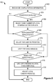
- FIG. 8 is a flowchart showing a configuration process 800 in which a videoconferencing system configures itself for broadcasting video signals to another system and receiving video signals from the other system. It should be understood that the following steps are exemplary, and the actual operation of a videoconferencing system may be altered from the steps the follow. Further, depending on the type of videoconference system, the particular room geometry, and other factors, it may be necessary upon a first videoconferencing session with another system to manually adjust the local components to establish a set of preset values for cameras and displays to use in future videoconferencing sessions. However, if the presets are known, configuration information is exchanged by a near-end system with a far-end system (Block 802). This configuration information may include information such as the number of video displays and video cameras available, and the aspect ratio of each display and camera, in addition to other information, and may be exchanged using the H.225 protocol, as discussed above.
- the near-end system determines whether the far-end system has more or fewer far-end displays than the number of camera at the near-end system (Block 804). If there are fewer far-end displays, the near-end system adjusts its cameras so that the video signals sent to the far-end system correspond to the number and settings of the far-end displays available at the far-end system (Block 806). This may include, for example, using fewer cameras than the near-end system has available, or adjusting the pan, tilt, and/or zoom of the near-end camera(s) to correspond to the available displays at the far-end system.
- the near-end system determines whether the far-end system has a narrower aspect ratio than the near-end system (Block 808). For example, the near-end system may determine that the far-end cameras each use a 4:3 aspect ratio, while the near-end displays each use a 16:9 aspect ratio. If this is the case, then the far-end camera presets need to be adjusted so that the signal sent to the near-end system appears to cover the full field of view of the far-end cameras when the near-end video displays crop and display the video signals from the far-end cameras. In other words, the far-end camera's presets are adjusted so that the cropped video signals from each far-end cameras correspond to the aspect ratio of the near-end video displays (Block 810).
- the near-end video displays crop the received video signals so that it fits in the viewable area of the displays (Block 812). If more than one near-end video display exists, the signals are cropped so that a continuous image is displayed on the multiple near-end video displays.
- a near-end system that uses a 4:3 aspect ratio may make a determination as to whether a far-end system uses a 16:9 aspect ratio. If the far-end system does have a wider aspect ratio than the near-end system, the near-end displays use a letterboxing effect to display the video signal from the far-end system (Block 816).
- the near-end system adjusts the near-end camera presets so that when the video signals from the near-end cameras are cropped at the far-end system, the cropped video signals have the appearance of a single, seamless image.
- each particular videoconferencing system 100, 200, 300, 400 is discussed as having a particular number of cameras and video monitors, and the video monitors for each system are described as using a particular aspect ratio, these features may be varied and are not limited to the embodiments discussed herein. In other words, different numbers of cameras and video monitors from different systems may be combined in manners similar to those discussed above. Similarly, other aspect ratios not discussed above may be sent and received by different systems in manners similar to those discussed above. Further, while a particular orientation of each system is shown according to various embodiments of the invention (e.g., in FIGS. 2-4 ), other orientations of cameras, displays, etc., may be used. In other words, video cameras and video displays may have different orientations which are accounted for by a user or administrator of the local system.
- sending configuration information at the beginning of a videoconferencing using known protocols allows two dissimilar videoconferencing systems to automatically configure themselves to send appropriate video information to the other system and to receive video information from the other system.
- a telepresence effect may be automatically created in two dissimilar videoconferencing systems without human intervention.
- an operator of each system does not have to manually position each camera to capture the correct field of view.
- a setup time of communicating videoconferencing systems may be reduced.
Landscapes
- Engineering & Computer Science (AREA)
- Multimedia (AREA)
- Signal Processing (AREA)
- Computer Networks & Wireless Communication (AREA)
- Studio Devices (AREA)
- Two-Way Televisions, Distribution Of Moving Picture Or The Like (AREA)
- Telephonic Communication Services (AREA)
Claims (15)
- Videokonferenz-Konfigurationsverfahren, umfassend:Empfangen (802) von Fern-End-Konfigurationsinformationen von einem Fern-End-Videokonferenzsystem (104) an einem Nah-End-Videokonferenzsystem (100), wobei die Fern-End-Konfigurationsinformationen Videohandhabung hinsichtlich Aufzeichnen und Anzeigen von Videos am Fern-End-Videokonferenzsystem (104) angeben, wobei die Fern-End-Konfigurationsinformationen ferner eine Fern-End-Anzahl von Videoanzeigen und Kameras angeben, die an dem Fern-End-Videokonferenzsystem (104) verwendbar sind;Konfigurieren, an dem Nah-End-Videokonferenzsystem (100), einer oder mehrerer Nah-End-Videokameras (112) auf Basis der Fern-End-Konfigurationsinformationen, um Nah-End-Video zum Senden an das Fern-End-Videokonferenzsystem (104) aufzuzeichnen; undKonfigurieren einer oder mehrerer Nah-End-Videoanzeigen (118) am Nah-End-Videokonferenzsystem (100) auf Basis der Fern-End-Konfigurationsinformationen, um vom Fern-End-Videokonferenzsystem (104) empfangenes Fern-End-Videomaterial anzuzeigen,wobei sich die Videohandhabung hinsichtlich Aufzeichnen und Anzeigen von Videos durch das Nah-End-Videokonferenzsystem (100) von dem Fern-End-Videokonferenzsystem (104) unterscheidet.
- Verfahren nach Anspruch 1, ferner umfassend Senden von Nah-End-Konfigurationsinformationen an das Fern-End-Videokonferenzsystem (104), wobei die Nah-End-Konfigurationsinformationen Videohandhabung hinsichtlich Aufzeichnen und Anzeigen von Videos am Nah-End-Videokonferenzsystem (100) angeben.
- Verfahren nach Anspruch 1 oder 2, wobei Konfigurieren der einen oder mehreren Nah-End-Videokameras (112) Anpassen (818) einer Nah-End-Anzahl der einen oder mehreren Kameras (112) zum Aufzeichnen von Nah-End-Video umfasst, so dass sie mit der Fern-End-Anzahl von Videoanzeigen übereinstimmt.
- Verfahren nach Anspruch 1, 2 oder 3, wobei Konfigurieren der einen oder mehreren Nah-End-Videokameras (112) Anpassen eines Blickwinkels (113) der einen oder mehreren Kameras (112) zum Aufzeichnen von Nah-End-Video umfasst.
- Verfahren nach einem der vorstehenden Ansprüche, wobei die Fern-End-Konfigurationsinformationen ein Fern-End-Seitenverhältnis umfasst, das bei dem Fern-End-Videokonferenzsystem (104) zur Videoaufzeichnung verwendbar ist.
- Verfahren nach einem der vorstehenden Ansprüche, wobei die Fern-End-Konfigurationsinformationen eine Identifikation des Fern-End-Videokonferenzsystems (104) umfasst.
- Verfahren nach einem der vorhergehenden Ansprüche, wobei das Nah-End-Videokonferenzsystem (100) ein anderes Seitenverhältnis als das Fern-End-Videokonferenzsystem (104) verwendet, und wobei Konfigurieren der einen oder mehreren Anzeigen (118) Konfigurieren der einen oder mehreren Anzeigen (118) umfasst, um das Seitenverhältnis an das Fern-End-Videokonferenzsystem (104) anzupassen.
- Verfahren nach einem der vorhergehenden Ansprüche, wobei die Fern-End-Konfigurationsinformationen ferner ein Seitenverhältnis angeben, das dem Fern-End-Videokonferenzsystem (104) zugeordnet ist, und wobei das Nah-End-Videokonferenzsystem (100) eine andere Anzahl von Videoanzeigen (118) aufweist oder ein anderes Seitenverhältnis als das Fern-End-Videokonferenzsystem (104) verwendet.
- Nah-End-Videokonferenzsystem, umfassend:eine Steuereinheit (120), die konfiguriert ist, Fern-End-Konfigurationsinformationen von einem Fern-End-Videokonferenzsystem (104) zu empfangen (802), wobei die Fern-End-Konfigurationsinformationen eine physikalische Konfiguration zur Handhabung von Video hinsichtlich Aufzeichnen und Anzeigen von Videos an dem Fern-End-Videokonferenzsystem (104) angeben, wobei die Fern-End-Konfigurationsinformationen ferner eine Fern-End-Anzahl von Videoanzeigen und Kameras angeben, die an dem Fern-End-Videokonferenzsystem (104) verwendbar sind;eine oder mehrere Nah-End-Kameras (112), die operativ mit der Steuereinheit (120) gekoppelt sind und konfigurierbar sind, um Nah-End-Videoinformationen zum Senden an das Fern-End-Videokonferenzsystem (104) basierend auf den Fern-End-Konfigurationsinformationen aufzuzeichnen; undein oder mehrere Nah-End-Videodisplays (118), die operativ mit der Steuereinheit (120) gekoppelt sind und konfigurierbar sind, um Fern-End-Videoinformationen basierend auf den Fern-End-Konfigurationsinformationen anzuzeigen,wobei das Nah-End-Videokonferenzsystem (100) eine andere physikalische Konfiguration zur Handhabung von Video hinsichtlich Aufzeichnen und Anzeigen von Videos hat als das Fern-End-Videokonferenzsystem (104).
- Nah-End-Videokonferenzsystem nach Anspruch 9, wobei die Steuereinheit (120) ferner konfiguriert ist, um Nah-End-Konfigurationsinformationen an das Fern-End-Videokonferenzsystem (104) zu senden.
- Nah-End-Videokonferenzsystem nach Anspruch 9 oder 10, wobei die Fern-End-Konfigurationsinformationen ein Seitenverhältnis am fernen Ende zum Anzeigen von Video umfasst.
- Nah-End-Videokonferenzsystem nach Anspruch 9, 10 oder 11, wobei die Fern-End-Konfigurationsinformationen eine Modellkennung des Fern-End-Videokonferenzsystems (104) umfasst.
- Nah-End-Videokonferenzsystem nach Anspruch 9, 10, 11 oder 12, wobei das Nah-End-Videokonferenzsystem (100) eine andere Anzahl von Videoanzeigen (118) aufweist als das Fern-End-Videokonferenzsystem (104).
- Nah-End-Videokonferenzsystem nach einem der Ansprüche 9-13, wobei das Nah-End-Videokonferenzsystem (100) ein anderes Seitenverhältnis nutzt als das Fern-End-Videokonferenzsystem (104).
- Nah-End-Videokonferenzsystem nach einem der Ansprüche 9-14, wobei die Fern-End-Konfigurationsinformationen ferner ein Seitenverhältnis angeben, das dem Fern-End-Videokonferenzsystem (104) zugeordnet ist, und wobei das Nah-End-Videokonferenzsystem (100) eine andere Anzahl von Videoanzeigen (118) aufweist oder ein anderes Seitenverhältnis als das Fern-End-Videokonferenzsystem (104) verwendet.
Applications Claiming Priority (2)
| Application Number | Priority Date | Filing Date | Title |
|---|---|---|---|
| US97953307P | 2007-10-12 | 2007-10-12 | |
| PCT/US2008/079523 WO2009049163A1 (en) | 2007-10-12 | 2008-10-10 | Configuring videoconferencing systems to create video sessions with realistic presence |
Publications (3)
| Publication Number | Publication Date |
|---|---|
| EP2201762A1 EP2201762A1 (de) | 2010-06-30 |
| EP2201762A4 EP2201762A4 (de) | 2013-11-27 |
| EP2201762B1 true EP2201762B1 (de) | 2020-03-18 |
Family
ID=40549592
Family Applications (1)
| Application Number | Title | Priority Date | Filing Date |
|---|---|---|---|
| EP08837376.6A Active EP2201762B1 (de) | 2007-10-12 | 2008-10-10 | Konfigurierung von videokonferenzsystemen zur herstellung von videositzungen mit realistischer präsenz |
Country Status (4)
| Country | Link |
|---|---|
| US (1) | US8217981B2 (de) |
| EP (1) | EP2201762B1 (de) |
| CN (2) | CN101874405B (de) |
| WO (1) | WO2009049163A1 (de) |
Families Citing this family (10)
| Publication number | Priority date | Publication date | Assignee | Title |
|---|---|---|---|---|
| NO329739B1 (no) * | 2008-12-23 | 2010-12-13 | Tandberg Telecom As | Fremgangsmate, anordning og dataprogram for a prosessere bilder i en konferanse mellom et flertall av videokonferanseterminaler |
| US8305421B2 (en) * | 2009-06-29 | 2012-11-06 | Lifesize Communications, Inc. | Automatic determination of a configuration for a conference |
| CN102025891B (zh) | 2009-09-11 | 2012-11-07 | 华为终端有限公司 | 一种图像处理方法及装置 |
| CN102082944B (zh) | 2009-11-30 | 2016-03-09 | 华为终端有限公司 | 一种包含远程呈现会场的会议控制方法、装置及系统 |
| CN102572417B (zh) * | 2010-12-17 | 2015-04-22 | 华为终端有限公司 | 发送、接收视频信息的方法及装置 |
| CN102761731B (zh) * | 2011-04-29 | 2015-09-09 | 华为终端有限公司 | 数据内容的显示方法、装置和系统 |
| CN103096018B (zh) | 2011-11-08 | 2016-11-23 | 华为技术有限公司 | 传输信息的方法和终端 |
| CN103905776B (zh) * | 2012-12-26 | 2018-01-16 | 华为技术有限公司 | 码流处理方法和系统、多点控制单元 |
| US9924252B2 (en) | 2013-03-13 | 2018-03-20 | Polycom, Inc. | Loudspeaker arrangement with on-screen voice positioning for telepresence system |
| JP6643928B2 (ja) * | 2016-03-22 | 2020-02-12 | アイホン株式会社 | インターホンシステム |
Family Cites Families (15)
| Publication number | Priority date | Publication date | Assignee | Title |
|---|---|---|---|---|
| WO1996008911A1 (en) * | 1994-09-16 | 1996-03-21 | Southwestern Bell Technology Resources, Inc. | Versatile multipoint video composition and bridging system |
| JP2000069461A (ja) | 1998-08-24 | 2000-03-03 | Canon Inc | カメラ制御システムおよびその制御方法およびクライアントおよびクライアントの制御を実行させるプログラムを記憶した記憶媒体 |
| US6625812B2 (en) * | 1999-10-22 | 2003-09-23 | David Hardin Abrams | Method and system for preserving and communicating live views of a remote physical location over a computer network |
| JP4340084B2 (ja) * | 2003-03-11 | 2009-10-07 | パナソニック株式会社 | 送信装置および送信方法 |
| US7034860B2 (en) * | 2003-06-20 | 2006-04-25 | Tandberg Telecom As | Method and apparatus for video conferencing having dynamic picture layout |
| NO318974B1 (no) * | 2003-07-07 | 2005-05-30 | Tandberg Telecom As | Distribuert MCU |
| JP4443181B2 (ja) * | 2003-10-15 | 2010-03-31 | 株式会社日立製作所 | コミュニケーションシステム及び方法 |
| US7139015B2 (en) * | 2004-01-20 | 2006-11-21 | Polycom, Inc. | Method and apparatus for mixing compressed video |
| US7113200B2 (en) * | 2004-05-21 | 2006-09-26 | Polycom, Inc. | Method and system for preparing video communication image for wide screen display |
| US20060002373A1 (en) * | 2004-06-30 | 2006-01-05 | Michael Denny | Terminals, methods, systems, and computer program products for providing video communications over a broadband connection based on a call via a PSTN |
| US7692683B2 (en) | 2004-10-15 | 2010-04-06 | Lifesize Communications, Inc. | Video conferencing system transcoder |
| GB2422065B (en) * | 2005-01-05 | 2008-12-17 | Codian Ltd | Video multi-conference unit (MCU) |
| JP4882288B2 (ja) | 2005-06-20 | 2012-02-22 | 富士ゼロックス株式会社 | 表示制御装置、システム及び表示制御方法 |
| US7742068B2 (en) * | 2005-09-14 | 2010-06-22 | Sorenson Communications, Inc. | Method and system for auto configuration in a video phone system |
| US8872879B2 (en) * | 2006-01-26 | 2014-10-28 | Polycom, Inc. | System and method for controlling videoconference with touch screen interface |
-
2008
- 2008-10-10 US US12/249,348 patent/US8217981B2/en active Active
- 2008-10-10 CN CN2008801177139A patent/CN101874405B/zh not_active Expired - Fee Related
- 2008-10-10 EP EP08837376.6A patent/EP2201762B1/de active Active
- 2008-10-10 CN CN201210497510.5A patent/CN103002246B/zh not_active Expired - Fee Related
- 2008-10-10 WO PCT/US2008/079523 patent/WO2009049163A1/en not_active Ceased
Non-Patent Citations (1)
| Title |
|---|
| None * |
Also Published As
| Publication number | Publication date |
|---|---|
| CN101874405A (zh) | 2010-10-27 |
| WO2009049163A1 (en) | 2009-04-16 |
| EP2201762A4 (de) | 2013-11-27 |
| CN101874405B (zh) | 2012-12-26 |
| US8217981B2 (en) | 2012-07-10 |
| CN103002246A (zh) | 2013-03-27 |
| CN103002246B (zh) | 2016-08-17 |
| US20090225152A1 (en) | 2009-09-10 |
| EP2201762A1 (de) | 2010-06-30 |
Similar Documents
| Publication | Publication Date | Title |
|---|---|---|
| EP2201762B1 (de) | Konfigurierung von videokonferenzsystemen zur herstellung von videositzungen mit realistischer präsenz | |
| US8264519B2 (en) | Telepresence system, method and computer program product | |
| CN102265613B (zh) | 用于处理在多个视频会议终端之间的会议中的图像的方法、设备 | |
| US9065974B2 (en) | System and method for combining a plurality of video streams generated in a videoconference | |
| US20020093531A1 (en) | Adaptive display for video conferences | |
| EP2024852A2 (de) | Systeme und verfahren zur steuerung eines telepräsenzsystems | |
| US20140247321A1 (en) | Methods and System for Simulated 3D Videoconferencing | |
| EP2277308A2 (de) | Virtuelle videokonferenz am runden tisch | |
| EP0572277B1 (de) | Bildkommunikationsgerät | |
| JP2008263636A (ja) | ワイドスクリーンディスプレイ用のビデオ通信画像を準備する方法及びシステム | |
| WO2010041954A1 (en) | Method, device and computer program for processing images during video conferencing | |
| WO2011091604A1 (zh) | 视频通信的方法、装置和系统 | |
| WO2011063763A1 (zh) | 一种包含远程呈现会场的会议控制方法、装置及系统 | |
| WO2010068115A1 (en) | Method for setting up communication sessions | |
| US8259624B2 (en) | Dynamic picture layout for video conferencing based on properties derived from received conferencing signals | |
| JPH0946591A (ja) | 画像処理装置及び画像処理システム | |
| WO2014192804A1 (ja) | デコーダ及び監視システム | |
| JP2008289091A (ja) | 画像表示装置及び監視カメラシステム | |
| JP2003023612A (ja) | 画像通信端末装置 | |
| US20150002609A1 (en) | Automated field of view adjustment based on screen size | |
| HK1140886B (en) | Configuring videoconferencing systems to create video sessions with realistic presence | |
| HK1140886A (en) | Configuring videoconferencing systems to create video sessions with realistic presence | |
| JPH05328342A (ja) | 映像信号処理装置および多地点間映像通信装置 | |
| JPH0946710A (ja) | 画像通信システムおよび画像通信装置 | |
| JP4140006B2 (ja) | 合成画像生成用撮影システム |
Legal Events
| Date | Code | Title | Description |
|---|---|---|---|
| PUAI | Public reference made under article 153(3) epc to a published international application that has entered the european phase |
Free format text: ORIGINAL CODE: 0009012 |
|
| 17P | Request for examination filed |
Effective date: 20100510 |
|
| AK | Designated contracting states |
Kind code of ref document: A1 Designated state(s): AT BE BG CH CY CZ DE DK EE ES FI FR GB GR HR HU IE IS IT LI LT LU LV MC MT NL NO PL PT RO SE SI SK TR |
|
| AX | Request for extension of the european patent |
Extension state: AL BA MK RS |
|
| REG | Reference to a national code |
Ref country code: HK Ref legal event code: DE Ref document number: 1140886 Country of ref document: HK |
|
| DAX | Request for extension of the european patent (deleted) | ||
| RAP1 | Party data changed (applicant data changed or rights of an application transferred) |
Owner name: POLYCOM, INC. |
|
| A4 | Supplementary search report drawn up and despatched |
Effective date: 20131025 |
|
| RIC1 | Information provided on ipc code assigned before grant |
Ipc: H04N 7/14 20060101AFI20131021BHEP Ipc: H04N 7/15 20060101ALI20131021BHEP |
|
| STAA | Information on the status of an ep patent application or granted ep patent |
Free format text: STATUS: EXAMINATION IS IN PROGRESS |
|
| 17Q | First examination report despatched |
Effective date: 20190218 |
|
| GRAP | Despatch of communication of intention to grant a patent |
Free format text: ORIGINAL CODE: EPIDOSNIGR1 |
|
| STAA | Information on the status of an ep patent application or granted ep patent |
Free format text: STATUS: GRANT OF PATENT IS INTENDED |
|
| INTG | Intention to grant announced |
Effective date: 20190926 |
|
| GRAJ | Information related to disapproval of communication of intention to grant by the applicant or resumption of examination proceedings by the epo deleted |
Free format text: ORIGINAL CODE: EPIDOSDIGR1 |
|
| STAA | Information on the status of an ep patent application or granted ep patent |
Free format text: STATUS: EXAMINATION IS IN PROGRESS |
|
| GRAR | Information related to intention to grant a patent recorded |
Free format text: ORIGINAL CODE: EPIDOSNIGR71 |
|
| GRAS | Grant fee paid |
Free format text: ORIGINAL CODE: EPIDOSNIGR3 |
|
| STAA | Information on the status of an ep patent application or granted ep patent |
Free format text: STATUS: GRANT OF PATENT IS INTENDED |
|
| GRAA | (expected) grant |
Free format text: ORIGINAL CODE: 0009210 |
|
| STAA | Information on the status of an ep patent application or granted ep patent |
Free format text: STATUS: THE PATENT HAS BEEN GRANTED |
|
| INTC | Intention to grant announced (deleted) | ||
| AK | Designated contracting states |
Kind code of ref document: B1 Designated state(s): AT BE BG CH CY CZ DE DK EE ES FI FR GB GR HR HU IE IS IT LI LT LU LV MC MT NL NO PL PT RO SE SI SK TR |
|
| INTG | Intention to grant announced |
Effective date: 20200211 |
|
| REG | Reference to a national code |
Ref country code: GB Ref legal event code: FG4D |
|
| REG | Reference to a national code |
Ref country code: DE Ref legal event code: R096 Ref document number: 602008062349 Country of ref document: DE |
|
| REG | Reference to a national code |
Ref country code: AT Ref legal event code: REF Ref document number: 1247260 Country of ref document: AT Kind code of ref document: T Effective date: 20200415 Ref country code: IE Ref legal event code: FG4D |
|
| PG25 | Lapsed in a contracting state [announced via postgrant information from national office to epo] |
Ref country code: FI Free format text: LAPSE BECAUSE OF FAILURE TO SUBMIT A TRANSLATION OF THE DESCRIPTION OR TO PAY THE FEE WITHIN THE PRESCRIBED TIME-LIMIT Effective date: 20200318 Ref country code: NO Free format text: LAPSE BECAUSE OF FAILURE TO SUBMIT A TRANSLATION OF THE DESCRIPTION OR TO PAY THE FEE WITHIN THE PRESCRIBED TIME-LIMIT Effective date: 20200618 |
|
| REG | Reference to a national code |
Ref country code: NL Ref legal event code: MP Effective date: 20200318 |
|
| PG25 | Lapsed in a contracting state [announced via postgrant information from national office to epo] |
Ref country code: LV Free format text: LAPSE BECAUSE OF FAILURE TO SUBMIT A TRANSLATION OF THE DESCRIPTION OR TO PAY THE FEE WITHIN THE PRESCRIBED TIME-LIMIT Effective date: 20200318 Ref country code: SE Free format text: LAPSE BECAUSE OF FAILURE TO SUBMIT A TRANSLATION OF THE DESCRIPTION OR TO PAY THE FEE WITHIN THE PRESCRIBED TIME-LIMIT Effective date: 20200318 Ref country code: BG Free format text: LAPSE BECAUSE OF FAILURE TO SUBMIT A TRANSLATION OF THE DESCRIPTION OR TO PAY THE FEE WITHIN THE PRESCRIBED TIME-LIMIT Effective date: 20200618 Ref country code: GR Free format text: LAPSE BECAUSE OF FAILURE TO SUBMIT A TRANSLATION OF THE DESCRIPTION OR TO PAY THE FEE WITHIN THE PRESCRIBED TIME-LIMIT Effective date: 20200619 Ref country code: HR Free format text: LAPSE BECAUSE OF FAILURE TO SUBMIT A TRANSLATION OF THE DESCRIPTION OR TO PAY THE FEE WITHIN THE PRESCRIBED TIME-LIMIT Effective date: 20200318 |
|
| REG | Reference to a national code |
Ref country code: LT Ref legal event code: MG4D |
|
| PG25 | Lapsed in a contracting state [announced via postgrant information from national office to epo] |
Ref country code: NL Free format text: LAPSE BECAUSE OF FAILURE TO SUBMIT A TRANSLATION OF THE DESCRIPTION OR TO PAY THE FEE WITHIN THE PRESCRIBED TIME-LIMIT Effective date: 20200318 |
|
| PG25 | Lapsed in a contracting state [announced via postgrant information from national office to epo] |
Ref country code: EE Free format text: LAPSE BECAUSE OF FAILURE TO SUBMIT A TRANSLATION OF THE DESCRIPTION OR TO PAY THE FEE WITHIN THE PRESCRIBED TIME-LIMIT Effective date: 20200318 Ref country code: LT Free format text: LAPSE BECAUSE OF FAILURE TO SUBMIT A TRANSLATION OF THE DESCRIPTION OR TO PAY THE FEE WITHIN THE PRESCRIBED TIME-LIMIT Effective date: 20200318 Ref country code: IS Free format text: LAPSE BECAUSE OF FAILURE TO SUBMIT A TRANSLATION OF THE DESCRIPTION OR TO PAY THE FEE WITHIN THE PRESCRIBED TIME-LIMIT Effective date: 20200718 Ref country code: SK Free format text: LAPSE BECAUSE OF FAILURE TO SUBMIT A TRANSLATION OF THE DESCRIPTION OR TO PAY THE FEE WITHIN THE PRESCRIBED TIME-LIMIT Effective date: 20200318 Ref country code: RO Free format text: LAPSE BECAUSE OF FAILURE TO SUBMIT A TRANSLATION OF THE DESCRIPTION OR TO PAY THE FEE WITHIN THE PRESCRIBED TIME-LIMIT Effective date: 20200318 Ref country code: PT Free format text: LAPSE BECAUSE OF FAILURE TO SUBMIT A TRANSLATION OF THE DESCRIPTION OR TO PAY THE FEE WITHIN THE PRESCRIBED TIME-LIMIT Effective date: 20200812 Ref country code: CZ Free format text: LAPSE BECAUSE OF FAILURE TO SUBMIT A TRANSLATION OF THE DESCRIPTION OR TO PAY THE FEE WITHIN THE PRESCRIBED TIME-LIMIT Effective date: 20200318 |
|
| REG | Reference to a national code |
Ref country code: AT Ref legal event code: MK05 Ref document number: 1247260 Country of ref document: AT Kind code of ref document: T Effective date: 20200318 |
|
| REG | Reference to a national code |
Ref country code: DE Ref legal event code: R097 Ref document number: 602008062349 Country of ref document: DE |
|
| PLBE | No opposition filed within time limit |
Free format text: ORIGINAL CODE: 0009261 |
|
| STAA | Information on the status of an ep patent application or granted ep patent |
Free format text: STATUS: NO OPPOSITION FILED WITHIN TIME LIMIT |
|
| PG25 | Lapsed in a contracting state [announced via postgrant information from national office to epo] |
Ref country code: IT Free format text: LAPSE BECAUSE OF FAILURE TO SUBMIT A TRANSLATION OF THE DESCRIPTION OR TO PAY THE FEE WITHIN THE PRESCRIBED TIME-LIMIT Effective date: 20200318 Ref country code: DK Free format text: LAPSE BECAUSE OF FAILURE TO SUBMIT A TRANSLATION OF THE DESCRIPTION OR TO PAY THE FEE WITHIN THE PRESCRIBED TIME-LIMIT Effective date: 20200318 Ref country code: AT Free format text: LAPSE BECAUSE OF FAILURE TO SUBMIT A TRANSLATION OF THE DESCRIPTION OR TO PAY THE FEE WITHIN THE PRESCRIBED TIME-LIMIT Effective date: 20200318 Ref country code: ES Free format text: LAPSE BECAUSE OF FAILURE TO SUBMIT A TRANSLATION OF THE DESCRIPTION OR TO PAY THE FEE WITHIN THE PRESCRIBED TIME-LIMIT Effective date: 20200318 |
|
| 26N | No opposition filed |
Effective date: 20201221 |
|
| PG25 | Lapsed in a contracting state [announced via postgrant information from national office to epo] |
Ref country code: PL Free format text: LAPSE BECAUSE OF FAILURE TO SUBMIT A TRANSLATION OF THE DESCRIPTION OR TO PAY THE FEE WITHIN THE PRESCRIBED TIME-LIMIT Effective date: 20200318 |
|
| PG25 | Lapsed in a contracting state [announced via postgrant information from national office to epo] |
Ref country code: SI Free format text: LAPSE BECAUSE OF FAILURE TO SUBMIT A TRANSLATION OF THE DESCRIPTION OR TO PAY THE FEE WITHIN THE PRESCRIBED TIME-LIMIT Effective date: 20200318 |
|
| REG | Reference to a national code |
Ref country code: CH Ref legal event code: PL |
|
| PG25 | Lapsed in a contracting state [announced via postgrant information from national office to epo] |
Ref country code: LU Free format text: LAPSE BECAUSE OF NON-PAYMENT OF DUE FEES Effective date: 20201010 Ref country code: MC Free format text: LAPSE BECAUSE OF FAILURE TO SUBMIT A TRANSLATION OF THE DESCRIPTION OR TO PAY THE FEE WITHIN THE PRESCRIBED TIME-LIMIT Effective date: 20200318 |
|
| REG | Reference to a national code |
Ref country code: BE Ref legal event code: MM Effective date: 20201031 |
|
| PG25 | Lapsed in a contracting state [announced via postgrant information from national office to epo] |
Ref country code: FR Free format text: LAPSE BECAUSE OF NON-PAYMENT OF DUE FEES Effective date: 20201031 |
|
| PG25 | Lapsed in a contracting state [announced via postgrant information from national office to epo] |
Ref country code: CH Free format text: LAPSE BECAUSE OF NON-PAYMENT OF DUE FEES Effective date: 20201031 Ref country code: BE Free format text: LAPSE BECAUSE OF NON-PAYMENT OF DUE FEES Effective date: 20201031 Ref country code: LI Free format text: LAPSE BECAUSE OF NON-PAYMENT OF DUE FEES Effective date: 20201031 |
|
| PG25 | Lapsed in a contracting state [announced via postgrant information from national office to epo] |
Ref country code: IE Free format text: LAPSE BECAUSE OF NON-PAYMENT OF DUE FEES Effective date: 20201010 |
|
| PG25 | Lapsed in a contracting state [announced via postgrant information from national office to epo] |
Ref country code: TR Free format text: LAPSE BECAUSE OF FAILURE TO SUBMIT A TRANSLATION OF THE DESCRIPTION OR TO PAY THE FEE WITHIN THE PRESCRIBED TIME-LIMIT Effective date: 20200318 Ref country code: MT Free format text: LAPSE BECAUSE OF FAILURE TO SUBMIT A TRANSLATION OF THE DESCRIPTION OR TO PAY THE FEE WITHIN THE PRESCRIBED TIME-LIMIT Effective date: 20200318 Ref country code: CY Free format text: LAPSE BECAUSE OF FAILURE TO SUBMIT A TRANSLATION OF THE DESCRIPTION OR TO PAY THE FEE WITHIN THE PRESCRIBED TIME-LIMIT Effective date: 20200318 |
|
| PGFP | Annual fee paid to national office [announced via postgrant information from national office to epo] |
Ref country code: GB Payment date: 20221019 Year of fee payment: 15 |
|
| REG | Reference to a national code |
Ref country code: GB Ref legal event code: 732E Free format text: REGISTERED BETWEEN 20230803 AND 20230809 |
|
| REG | Reference to a national code |
Ref country code: DE Ref legal event code: R081 Ref document number: 602008062349 Country of ref document: DE Owner name: HEWLETT-PACKARD DEVELOPMENT COMPANY, L.P., SPR, US Free format text: FORMER OWNER: POLYCOM, INC., SAN JOSE, CALIF., US Ref country code: DE Ref legal event code: R082 Ref document number: 602008062349 Country of ref document: DE |
|
| PGFP | Annual fee paid to national office [announced via postgrant information from national office to epo] |
Ref country code: DE Payment date: 20230920 Year of fee payment: 16 |
|
| GBPC | Gb: european patent ceased through non-payment of renewal fee |
Effective date: 20231010 |
|
| PG25 | Lapsed in a contracting state [announced via postgrant information from national office to epo] |
Ref country code: GB Free format text: LAPSE BECAUSE OF NON-PAYMENT OF DUE FEES Effective date: 20231010 |
|
| PG25 | Lapsed in a contracting state [announced via postgrant information from national office to epo] |
Ref country code: GB Free format text: LAPSE BECAUSE OF NON-PAYMENT OF DUE FEES Effective date: 20231010 |
|
| REG | Reference to a national code |
Ref country code: DE Ref legal event code: R119 Ref document number: 602008062349 Country of ref document: DE |
|
| PG25 | Lapsed in a contracting state [announced via postgrant information from national office to epo] |
Ref country code: DE Free format text: LAPSE BECAUSE OF NON-PAYMENT OF DUE FEES Effective date: 20250501 |