EP2202029A2 - Tête de support d'outil pour une machine de nettoyage/affilage manuelle et machine de nettoyage/affilage manuelle - Google Patents
Tête de support d'outil pour une machine de nettoyage/affilage manuelle et machine de nettoyage/affilage manuelle Download PDFInfo
- Publication number
- EP2202029A2 EP2202029A2 EP09180289A EP09180289A EP2202029A2 EP 2202029 A2 EP2202029 A2 EP 2202029A2 EP 09180289 A EP09180289 A EP 09180289A EP 09180289 A EP09180289 A EP 09180289A EP 2202029 A2 EP2202029 A2 EP 2202029A2
- Authority
- EP
- European Patent Office
- Prior art keywords
- abutment
- tool
- holding head
- space
- grinding machine
- Prior art date
- Legal status (The legal status is an assumption and is not a legal conclusion. Google has not performed a legal analysis and makes no representation as to the accuracy of the status listed.)
- Granted
Links
Images




Classifications
-
- B—PERFORMING OPERATIONS; TRANSPORTING
- B24—GRINDING; POLISHING
- B24B—MACHINES, DEVICES, OR PROCESSES FOR GRINDING OR POLISHING; DRESSING OR CONDITIONING OF ABRADING SURFACES; FEEDING OF GRINDING, POLISHING, OR LAPPING AGENTS
- B24B23/00—Portable grinding machines, e.g. hand-guided; Accessories therefor
- B24B23/04—Portable grinding machines, e.g. hand-guided; Accessories therefor with oscillating grinding tools; Accessories therefor
-
- B—PERFORMING OPERATIONS; TRANSPORTING
- B24—GRINDING; POLISHING
- B24B—MACHINES, DEVICES, OR PROCESSES FOR GRINDING OR POLISHING; DRESSING OR CONDITIONING OF ABRADING SURFACES; FEEDING OF GRINDING, POLISHING, OR LAPPING AGENTS
- B24B23/00—Portable grinding machines, e.g. hand-guided; Accessories therefor
- B24B23/02—Portable grinding machines, e.g. hand-guided; Accessories therefor with rotating grinding tools; Accessories therefor
-
- B—PERFORMING OPERATIONS; TRANSPORTING
- B24—GRINDING; POLISHING
- B24B—MACHINES, DEVICES, OR PROCESSES FOR GRINDING OR POLISHING; DRESSING OR CONDITIONING OF ABRADING SURFACES; FEEDING OF GRINDING, POLISHING, OR LAPPING AGENTS
- B24B41/00—Component parts such as frames, beds, carriages, headstocks
- B24B41/002—Grinding heads
-
- B—PERFORMING OPERATIONS; TRANSPORTING
- B24—GRINDING; POLISHING
- B24B—MACHINES, DEVICES, OR PROCESSES FOR GRINDING OR POLISHING; DRESSING OR CONDITIONING OF ABRADING SURFACES; FEEDING OF GRINDING, POLISHING, OR LAPPING AGENTS
- B24B55/00—Safety devices for grinding or polishing machines; Accessories fitted to grinding or polishing machines for keeping tools or parts of the machine in good working condition
- B24B55/04—Protective covers for the grinding wheel
- B24B55/05—Protective covers for the grinding wheel specially designed for portable grinding machines
-
- B—PERFORMING OPERATIONS; TRANSPORTING
- B24—GRINDING; POLISHING
- B24B—MACHINES, DEVICES, OR PROCESSES FOR GRINDING OR POLISHING; DRESSING OR CONDITIONING OF ABRADING SURFACES; FEEDING OF GRINDING, POLISHING, OR LAPPING AGENTS
- B24B55/00—Safety devices for grinding or polishing machines; Accessories fitted to grinding or polishing machines for keeping tools or parts of the machine in good working condition
- B24B55/06—Dust extraction equipment on grinding or polishing machines
- B24B55/10—Dust extraction equipment on grinding or polishing machines specially designed for portable grinding machines, e.g. hand-guided
- B24B55/102—Dust extraction equipment on grinding or polishing machines specially designed for portable grinding machines, e.g. hand-guided with rotating tools
-
- B—PERFORMING OPERATIONS; TRANSPORTING
- B24—GRINDING; POLISHING
- B24B—MACHINES, DEVICES, OR PROCESSES FOR GRINDING OR POLISHING; DRESSING OR CONDITIONING OF ABRADING SURFACES; FEEDING OF GRINDING, POLISHING, OR LAPPING AGENTS
- B24B55/00—Safety devices for grinding or polishing machines; Accessories fitted to grinding or polishing machines for keeping tools or parts of the machine in good working condition
- B24B55/06—Dust extraction equipment on grinding or polishing machines
- B24B55/10—Dust extraction equipment on grinding or polishing machines specially designed for portable grinding machines, e.g. hand-guided
- B24B55/105—Dust extraction equipment on grinding or polishing machines specially designed for portable grinding machines, e.g. hand-guided with oscillating tools
-
- B—PERFORMING OPERATIONS; TRANSPORTING
- B24—GRINDING; POLISHING
- B24B—MACHINES, DEVICES, OR PROCESSES FOR GRINDING OR POLISHING; DRESSING OR CONDITIONING OF ABRADING SURFACES; FEEDING OF GRINDING, POLISHING, OR LAPPING AGENTS
- B24B7/00—Machines or devices designed for grinding plane surfaces on work, including polishing plane glass surfaces; Accessories therefor
- B24B7/10—Single-purpose machines or devices
- B24B7/18—Single-purpose machines or devices for grinding floorings, walls, ceilings or the like
- B24B7/186—Single-purpose machines or devices for grinding floorings, walls, ceilings or the like with disc-type tools
Definitions
- the invention relates to a tool holding head for a hand-held cleaning / grinding machine, comprising a plate device which is fixed or fixable on the cleaning / grinding machine, and a tool receiving device on which a tool for surface treatment is fixed or fixable and which relative to the plate means to a Rotation axis is rotatable, wherein on the plate means a bearing device is elastically mounted on a processing surface by spring elements and the abutment means surrounds the tool receiving device.
- the invention further relates to a hand-held cleaning / grinding machine.
- a hand-held grinding machine with a pivotable tool head which is in the form of a long-necked, is in the EP 1 719 581 A1 described.
- a hand-held cleaning / grinding machine which has a tool head for one or more cleaning tools and / or grinding tools.
- a grinding tool which comprises a holding device, a head device and at least one pivoting device.
- a brush ring can be arranged be, wherein the brush ring may be positioned over one or more biasing elements in a channel.
- a grinding device in which a sliding ring is removably mounted on the edge of a hood.
- a sanding pad and the sliding ring are adjustable relative to each other so that the front edge of the sliding ring and the front of the sanding plate are aligned.
- the invention has for its object to provide a tool holding head of the type mentioned, with which cleaning operations and / or grinding operations can be performed with a hand-held cleaning / grinding machine by a user in a simple way with optimized processing results.
- a first fixing point of the spring elements on the plate means and a second fixing point on the abutment means are spaced in a circumferential direction, wherein the distance in the circumferential direction is greater than a width of the corresponding spring element, or the spring elements are radially oriented spring tongues.
- the tool receiving device holds a tool such as a brush tool or a grinding tool such as a grinding wheel. During the machining process, this tool moves, for example, rotating or oscillating.
- the abutment surrounds the tool receiving device and thus also the tool and prevents, for example, grinding dust from escaping in large quantities from the processing area. This improves the extraction of sanding dust, as a kind of ab sealed closed space is provided by the investment facility. It also spills are avoided.
- the contact device is elastic and in particular resiliently mounted. This allows the abutment to adapt to the machining area. It is thus possible, for example, to compensate for bumps and to ensure despite unevenness for a good seal of the "workspace".
- the elastic storage gives a kind of automatic adaptation to the processing surface.
- the investment device which is elastically mounted, has a support function and dampens vibrations. This facilitates the operability for a user.
- the solution according to the invention can also be used if cleaning operations are to be carried out.
- the investment facility for example, the discharge of dirty water from the "working space" is minimized.
- the tool holding head can be used for a cleaning machine, for a grinding machine or for a machine that has both a cleaning function and a sanding function.
- the spring elements are radially aligned (based on a plan view of the spring elements) or a first fixation point of the spring elements on the plate means and a second fixation point of the spring elements on the abutment means in a circumferential direction are spaced, said distance being greater than a width of the corresponding spring elements.
- the spring elements preferably have a central axis along which the respective spring elements extend, with their central axis having a component in the circumferential direction when the spring elements are fixed.
- the length of the spring elements in the circumferential direction is greater and for example at least twice or at least three times or at least four times greater than their length in the radial direction.
- the spring elements can also have a height extent parallel to the axis of rotation. By said formation of the spring elements with an extension in the circumferential direction a greater spring travel is achieved. It will also be a snap effect for the Prevents spring elements, which can in principle arise when the spring elements are aligned with their central axis only radially.
- the investment device comprises a brush ring and / or lip ring.
- a brush ring is formed for example by a plurality of bristle bundles.
- a lip wreath includes one or more sealing lips.
- a combination of brushes and lips, for example, is also possible.
- a plurality of spring elements are provided for the elastic mounting of the contact device.
- the investment device can be stored in a simple manner resiliently on the plate device.
- a space requirement for the elastic mounting of the contact device is minimized, so that, for example, an extraction of grinding dust or the like is at most minimally influenced.
- the elastic mounting of the contact device is ensured even when dirty.
- the arrangement and design of the spring elements is optimized so that in particular the above-mentioned advantages are achieved.
- the elastic support is too hard, then a user for surface finishing must provide an (unnecessarily) large amount of force to keep a machining tool, such as a grinding wheel, in contact with the surface to be machined. If the elastic support is too soft, then, for example, the above-mentioned support function is not or not fully achieved.
- the spring elements are arranged distributed around the axis of rotation, that is, distributed in a circumferential direction relative to the axis of rotation. This results in a floating mounting of the contact device on the plate device, so that the investment facility Simple way to different surface textures of a processing area is customizable.
- the distribution of the spring elements about the axis of rotation and / or the hardness of the spring elements is dependent on the pressure distribution in the surface treatment.
- the spring elements are evenly distributed around the axis of rotation and the spring elements are all the same hard.
- the pressure distribution in the surface machining is asymmetrical. Such an asymmetry can arise, for example, in that the axis of rotation does not pierce the center of gravity of the tool head, but that a corresponding piercing point is at a distance from the center of gravity.
- the spring elements are favorably distributed not evenly about the axis of rotation, but adjacent spring elements have in the region of greater pressure a smaller distance than in a region in which there is a smaller pressure.
- spring elements of different hardness can be used at different locations. For example, in areas with greater pressure harder spring elements can be used.
- the spring elements are designed as spring tongues.
- the spring elements are produced by metallic platelets or plates made of a plastic material which has corresponding elastic properties.
- Such spring elements can be dimensioned and fixed in a simple manner. They can be made relatively wide, so that they can be screwed or welded in a simple manner with the plate device and the contact device, for example.
- the spring elements are in a first room arranged, which surrounds a second space, wherein the first space from the second space is at least fluid-tightly separated and the second space is closer to the axis of rotation than the first space.
- the second space is firmly or switchably separated fluid-tight from the first space. This can be used, for example, to achieve a better suction effect.
- a switchability of the fluid-tightness (in the sense that the fluid-tightness can be reversed) can be used, for example, to achieve suction of the tool head.
- At least one suction opening opens into the second space.
- a suction device is connected or connectable, via which, for example, grinding dust can be sucked from the processing area.
- the spring elements are connected to the plate device and the contact device.
- the spring elements are connected to a first region near a first end to the abutment means connected to a second region in the vicinity of an opposite second end of the plate means.
- the plate device has an upper side, wherein holders for the spring elements are arranged on an inner side of the upper side.
- holders for the spring elements are arranged on an inner side of the upper side.
- a movement direction of the contact device relative to the plate device by the elastic mounting of the contact device the plate means is parallel with an acute angle to the axis of rotation. Due to the parallel mobility, an optimized support can be achieved with optimum sealing. The optimum sealing is also ensured if surface irregularities or the like are present, by allowing tilting of the abutment device relative to the axis of rotation.
- the abutment device is elastically mounted on the plate device such that without application of force, an abutment side of the abutment device projects beyond a receiving side of the tool receptacle device.
- the abutment device is pressed against the machining area by the elastic mounting, thus ensuring an optimized sealing.
- the abutment device prefferably be mounted on the plate device such that, without exerting force, the abutment side of the abutment device protrudes beyond a machining side of a tool held on the tool receiving device.
- the investment device surrounds a processing area and seals it at least approximately from an exterior space.
- an abutment side of the abutment device can protrude beyond a machining side of the tool without applying force.
- the tool can be placed on the surface treatment area with one machining side and can act on it.
- the abutment is pressed in the direction of the plate means, wherein the corresponding force is applied by a user or possibly already by the weight of the cleaning / grinding machine or the tool head.
- the abutment is pressed against the surface treatment area and it is provided for an optimized seal. This, in turn, the proportion, for example, to grinding dust or even Splashing, which can get over the investment device in the outer space, minimized.
- the abutment device comprises one or more abutment elements, which are inserted into a strip.
- the contact elements can be replaced easily when worn.
- the plate device comprises a housing which has a side part which surrounds the abutment device in a partial region and laterally covers it in the partial region. As a result, storage of the abutment device on the plate device relative to the outer space can be covered laterally.
- At least one blocking surface may be provided which limits the elastic mobility of the abutment device relative to the plate device. As a result, it can be avoided, for example, that the contact device is pressed too far into a housing of the plate device.
- the blocking surface is arranged and designed such that, in each position of the contact device, an abutment side of the abutment device projects beyond a housing of the plate device relative to the plate device. This prevents that the investment device can completely immerse in the housing. This in turn prevents the abutment can jam in the housing, which can block their mobility. Furthermore, it is ensured that the contact side of the abutment device rests on a processing surface. (In particular, the blocking surface is then arranged and designed such that in every position of the abutment device the abutment side projects beyond a tool surface.)
- the distance of the fixing position in the circumferential direction is at least twice as large as the width of the corresponding one Spring element. As a result, a large spring travel is provided at a minimized radial distance.
- a length of the spring element in the circumferential direction is at least twice as large as a length in the radial direction. It is provided a large travel and a snap action is prevented.
- a spring element has a central axis along which the spring element extends, wherein the central axis has a component in the circumferential direction and a component in the radial direction.
- a hand-held cleaning / grinding machine is provided on which a tool holding head according to the invention is releasably or firmly fixed.
- the corresponding cleaning / grinding machine is for example designed as in the EP 1 719 581 A1 or in the EP 1 961 518 A1 described.
- the hand-held cleaning / grinding machine comprises a suction device, which is connected to the plate device to the at least one suction opening.
- a suction device which is connected to the plate device to the at least one suction opening.
- the hand-held cleaning / grinding machine includes an electric motor for driving a shaft connected to the tool-holding head.
- the electric motor provides torque for rotation of the tool receiving device.
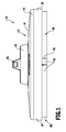
- FIGS. 1 to 5 shown and designated there with 10 An embodiment of a tool holding head according to the invention, which in the FIGS. 1 to 5 shown and designated there with 10, is used for Use in connection with a hand-held cleaning / grinding machine for wall, floor or ceiling work.
- the machine can be designed purely as a cleaning machine, purely as a grinding machine or as a machine, which can be used both as a cleaning machine and as a grinding machine.
- the corresponding cleaning / grinding machine is designed as a long-necked machine. Examples of such long-necked machines are in the EP 1 719 581 A1 and in the EP 1 961 518 A1 discloses, to which reference is expressly made.
- the tool holding head 10 comprises a plate device 12, via which the tool holding head 10 is fixedly or detachably fixed to the cleaning / grinding machine.
- the plate device 12 in this case has a housing 14 with an upper side 16.
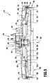
- the housing 14 is cup-shaped with a side part 18. Between the upper side 16 and the side part 18, a space region 20 is formed ( FIG. 5 ), on which at least partially a tool receiving device 22 is arranged.
- the tool holding head 10 has a dome-shaped region 24 on its upper side.
- the tool holding head 10 is detachably coupled to the cleaning / grinding machine.
- a fixing device 26 is provided.
- a bearing device 28 for rotatably supporting the tool receiving device 22 relative to the disk device 12 is arranged on the dome-shaped region 24.
- the bearing device 28 comprises a shaft 30 which is rotatably connected to the tool receiving device 22 and is rotatably mounted in a bearing element 32.
- the reduction device 34 is in turn coupled to a shaft 36 which is rotatably connected to a shaft, such as a flexible shaft, the cleaning / grinding machine connected or connected.
- the waves 30 and 36 are rotatable about a rotation axis 38.
- the rotation axis 38 is a rotation axis of the tool receiving device 22.
- the tool receiving device 22 it is possible for the tool receiving device 22 to rotate about the rotational axis 38 or to oscillate in a driven manner, depending on the configuration of the tool holding head 10.
- the reduction device 34 serves to lower the rotational speed of the tool receiving device 22 in comparison to the rotational speed of the shaft 36 and thus the rotational speed of a shaft of the cleaning / grinding machine.
- the reduction unit 34 is optional.
- the tool receiving device 22 is driven by a motor and in particular an electric motor, which sits outside the tool holding head 10. It will be on the above mentioned EP 1 961 518 A1 and EP 1 719 581 A1 directed.
- the plate device 12 is fixed relative to the cleaning / grinding machine and the tool holder 22 is rotatable about the axis of rotation 38 relative to the plate means 12 and thus also relative to the cleaning / grinding machine ,
- the tool receiving device 22 has a receiving side 40, on which a tool, which is in particular disc-shaped, can be applied. It is possible that the tool, such as a grinding wheel, via a Velcro connection device on the receiving side 40 is fixable. Other fixation options can be provided. For example, a brush tool or a combination tool may be screwed or integrally formed on the tool receiving device.
- a first space 42 and a second space 44 are formed below the upper surface 16 of the plate device 12 and above the tool device 22.
- the first space 42 is, for example, an annular space surrounding the second space 44.
- the first space 42 is bounded by the side part 18 of the housing 14.
- the second space 44 which is separate from the first space 42, surrounds the storage facility 28.
- an encircling web 48 is arranged on an inner side 46 of the upper side 16 of the housing 14.
- the web protrudes away from the housing 14 in the direction of the tool receiving device 22, without touching it.
- the web 48 is for example cylindrical.
- a corresponding circumferential strip 50 is arranged in the region of the web 48, which has parallel spaced opposite strip elements 52a, 52b. In a gap 54 between these strip elements 52a, 52b of the web 48 is immersed. As a result, a labyrinth seal is formed and the second space 44 is at least approximately fluid-tightly separated from the first space 42.
- first space 42 and the second space 44 It is in principle possible for one or more closable openings to be arranged between the first space 42 and the second space 44. As a result, the fluid communication between the first space 42 and the second space 44 is switchable.
- a suction opening 56 which can be connected or connected to a suction device of the cleaning / grinding machine.
- the suction device of the cleaning / grinding machine can be connected, for example, to a vacuum cleaner or the like. It can then be sucked off via the suction device via the second space 44, for example, grinding dust.
- the fluid-tight separation between the first space 42 and the second space 44 allows for improved suction.
- a suction hose is connected or connected as part of the suction device.
- the tool holding head 10 comprises a contact device 58, which can be applied with a contact side 60 to a processing surface.
- the abutment means 58 surrounds the tool receiving means 22 and a tool held thereon and, when in contact with a machining surface, covers a machining area and also a tool laterally.
- the abutment device comprises one or more abutment elements 62 of equal height in their length direction, which are oriented with their height direction substantially parallel to the axis of rotation 38 and, as mentioned above, with respect to a circumferential direction to the axis of rotation 38, the tool holder 22 surrounded.
- the one or more abutment members 62 are retained on a ledge 64 which is positioned in the first space 42.
- the bar 64 which may be formed in one or more parts, is, for example, annular. It has a receiving region 66, in which the or the contact elements 62 are fixed inserted.
- An abutment element 62 is, for example, a brush element or a lip element. Accordingly, then the contact device 58 is formed as a brush ring with a plurality of brushes or as a lip ring with a or a plurality of lips, which surrounds the tool receiving device 22 in the manner of a wall.
- the contact device 58 is resilient ("floating") and thus elastically held on the plate device 12.
- a plurality of spring elements 68 formed as spring tongues 68 are provided, which are in particular plate-shaped.
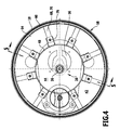
- Fig. 4 are the spring tongues 70 in the plan view from below oriented radially relative to the axis of rotation 38. They are slightly bent so that they also have a height extension:
- the spring elements 68 are each connected to a first region 72 with the bar 64 and connected to a second region 74 each having a holder 76 which on the inside 46 of the top 16 of the Housing 14 is positioned. In the non-force-loaded state, the first area 72 and the second area 74 are at different heights relative to the axis of rotation 38.
- the spring elements 68 are arranged distributed around the axis of rotation 38 ( Figures 3 and 4 ).
- the distribution of the spring elements 68 is basically chosen so that it is adapted to the expected pressure distribution in the surface treatment.
- the expected pressure distribution basically depends on how the tool holding head is formed and in particular how its center of gravity lies relative to the axis of rotation 38.
- the spring elements 68 evenly distributed around the axis of rotation 38 to be arranged. In the uniform distribution adjacent spring elements 68 have the same distance.
- the spring elements 68 are not evenly distributed and / or spring elements 68 of different hardness are used.
- the spring elements 68 may be arranged at a smaller distance from one another than in an area in which smaller pressures act.
- the holders 76 protrude parallel to the axis of rotation 38 from the inner side 46 of the housing 14. As a result, a spring element 68 with the second region 74 can be fixed to the plate device 12 at a distance from this inner side 46.
- the abutment side 60 (for abutment with a processing surface) of the abutment device 58 protrudes beyond the receiving side 40 (abutment side) of the tool receiving device 22. If a suitable tool is used, then this plant side 60 also projects beyond a corresponding processing surface of the tool.
- the abutment means 58 is elastically displaced in a direction 86 to the top 16 of the housing 14.
- the direction 86 is parallel or at an acute angle to the axis of rotation 38.
- the spring elements 68 are arranged and formed so that a mobility of the abutment means 58 in the direction 86 is enabled when power is applied.
- the direction 86 does not have to be exactly parallel to the axis of rotation 38, depending on the processing surface. In the case of uneven surfaces, a relative tilting of the abutment device 58 relative to the axis of rotation 38 can take place.
- the abutment device 58 is not rotated during rotation of the tool receiving device 22 and a tool held thereon.
- the abutment device 58 at least approximately seals off a surface treatment area to an outer space laterally. This allows an optimized Schleifstaubabsaugung achieve. Due to the elastic, resilient arrangement of the contact device 58 on the plate device 12, the "seal" can be positioned relative to the outer space. Due to its elastic mobility, the abutment device 58 can adapt to the surface area to be machined, wherein, as mentioned above, a tiltability relative to the axis of rotation 38 is also possible. The grinding dust discharge into the outside space is thereby minimized.
- the floating bearing device 58 has a supporting function in surface treatment for a cleaning / grinding machine.
- the abutment 58 dampens vibrations. As a result, the cleaning / grinding machine runs quieter, that is, fluttering of the cleaning / grinding machine during surface treatment is prevented.
- the tool holding head 10 functions as follows:
- the tool holding head 10 is detachable or unsolvable for the processing of a Surface area fixed to a cleaning / grinding machine.
- the contact side 60 of the abutment 58 abuts against the surface treatment area.
- the abutment means 58 on their elastic support sufficient to push back that a processing side of a tool on the surface processing area, or a user must by appropriate (possibly additional) pressure exercise the tool, which by the Tool holder 22 is held, press against the processing area. (When a ceiling work is performed or a wall work, in which the effective weight of the cleaning / grinding machine is reduced, an additional effort of the user is required.)
- the abutment means 58 is movable relative to the plate means 12. This is in FIG. 1 indicated by the double arrow 78. In the FIGS. 1 to 3 and 5 In each case, a first position 80 of the contact device 58 is shown, in which the contact side 60 projects furthest beyond the housing 14.
- the tool holder 22 is driven rotated and rotated, for example, rotated or oscillating.
- a suitably held tool such as a grinding wheel, acts on the surface treatment area and creates grinding dust.
- This space 88 is in fluid communication with the second space 44 (specifically, through openings 84 in a tool and the tool receiving device). Through the second space 44 can be sucked through the suction 56 grinding dust.
- the inventive solution can be 10 with optimized design of the tool holding head optimized grinding results or cleaning results obtained.
- a processing space is fluidly effectively sealed by the abutment 58 against an outside space to provide for optimized grinding dust removal or the like. Due to the elastic mounting of the abutment device 58 via the spring elements 68 on the housing 14, adaptability to asperities and the like in a simple and, in particular for the user, automatic manner is possible.
- the plate device 12 thereby provides a blocking surface 90, to which the bar 64 of the contact device 58 can be applied.
- the locking surface 90 in combination with a corresponding locking surface of the bar 64, the mobility of the abutment means 58 is limited relative to the plate means 12 and a too far immersion of the abutment means 58 in the housing 14 is thereby prevented.
- the blocking surface 90 is formed, for example, on a rib 92, which is arranged on the inner side 46 of the housing 14.
- the blocking surface 90 is an annular surface.
- the locking surface 90 defines the second position 82 of the abutment means 58. The abutment 58 is thereby movable between the second position 82 and the first position 80.
- the blocking surface 90 is arranged in particular so that even when investing in the blocking surface 90 (in the second position 82) projects the abutment side 60 of the abutment device 58 over the housing 14. Thereby, a complete immersion of the abutment means 58 is prevented in the housing 14, and it remains the mobility of the abutment means 58 ensured, for example, jamming within the housing 14 is prevented. As a result, the investment function of the investment device 58 is ensured.
- FIGS. 6 and 7 shown and designated therein by 102 Another embodiment of a tool holding head according to the invention, which in the FIGS. 6 and 7 shown and designated therein by 102, comprises a plate means 104 with a housing 106.
- An abutment means 108 is resiliently mounted on the plate means 104.
- a plurality of spring elements 110 are provided.
- the abutment device 108 has a strip 112, in which one or more abutment elements 62 are inserted.
- holders 116 are arranged on an inner side 114 of the housing 106.
- the number of holders 116 corresponds to the number of spring elements 110.
- the respective spring elements 110 are connected to the respective holders 116 via a first fixing point 118. Via a respective second fixation point 120 they are connected to the bar 112. As a result, the contact device 108 is mounted elastically on the plate device 104.
- the spring elements 68 are radially aligned; the fixing points on the plate means 12 and the abutment means 58 are not spaced apart in a circumferential direction.
- the first fixing point 118 and the second fixing point 120 of a respective spring element 110 are spaced in a circumferential direction 122.
- the distance between the first fixation site 118 and the second fixation site 120 in the circumferential direction 122 is In particular, the said distance is at least twice as large as the width B. (The width B is relative to the radial direction 124.) Further, the distance between the first fixing point 118 and the second fixing point 120 in the circumferential direction (considerably) larger than the distance in the radial direction.
- a spring element 110 has a central axis 126, along which the spring element 110 extends.
- the central axis 126 has a component in the circumferential direction 122.
- the length of the spring member 110 in the circumferential direction 122 is considerably larger than the length of the spring member 110 in the radial direction 124. Specifically, the length in the circumferential direction is at least twice as long as the length in the radial direction 124.
- the holders 116 are connected via ribs 128a, 128b to a wall 130 which surrounds a space corresponding to the second space 44.
- This wall 130 is on the inside 114 from. Further, the ribs 128a, 128b are directly connected to the inner side 114.
- adjacent holders 116 are connected via ribs 132.
- These ribs 132 are oriented, for example, in the circumferential direction. They ensure lateral stability.
- the tool holding head 102 functions as described in connection with the tool holding head 10.
Landscapes
- Engineering & Computer Science (AREA)
- Mechanical Engineering (AREA)
- Finish Polishing, Edge Sharpening, And Grinding By Specific Grinding Devices (AREA)
- Cleaning In General (AREA)
Applications Claiming Priority (1)
| Application Number | Priority Date | Filing Date | Title |
|---|---|---|---|
| DE102008064564A DE102008064564A1 (de) | 2008-12-23 | 2008-12-23 | Werkzeughaltekopf für eine handgehaltene Reinigungs-/Schleifmaschine und handgehaltene Reinigungs-/Schleifmaschine |
Publications (3)
| Publication Number | Publication Date |
|---|---|
| EP2202029A2 true EP2202029A2 (fr) | 2010-06-30 |
| EP2202029A3 EP2202029A3 (fr) | 2011-01-19 |
| EP2202029B1 EP2202029B1 (fr) | 2012-02-29 |
Family
ID=41800478
Family Applications (1)
| Application Number | Title | Priority Date | Filing Date |
|---|---|---|---|
| EP09180289A Not-in-force EP2202029B1 (fr) | 2008-12-23 | 2009-12-22 | Tête de support d'outil pour une machine de nettoyage/affilage manuelle et machine de nettoyage/affilage manuelle |
Country Status (3)
| Country | Link |
|---|---|
| EP (1) | EP2202029B1 (fr) |
| AT (1) | ATE547202T1 (fr) |
| DE (1) | DE102008064564A1 (fr) |
Cited By (14)
| Publication number | Priority date | Publication date | Assignee | Title |
|---|---|---|---|---|
| EP2505308A1 (fr) * | 2011-03-31 | 2012-10-03 | Makita Corporation | Outil électrique |
| ITMI20111434A1 (it) * | 2011-07-29 | 2013-01-30 | Guido Valentini | Platorello a doppia camera di aspirazione |
| WO2014083243A1 (fr) * | 2012-11-29 | 2014-06-05 | Oy Kwh Mirka Ab | Dispositif et procédé de broyage de produits sphériques |
| CN103862351A (zh) * | 2012-12-13 | 2014-06-18 | 苏州宝时得电动工具有限公司 | 偏心旋转摆动类工具 |
| BE1021527B1 (fr) * | 2014-03-05 | 2015-12-08 | Blastrac B.V. | Meuleuse et procede de meulage d'une surface de sol |
| WO2016120715A1 (fr) * | 2015-01-27 | 2016-08-04 | Polirtlak D.O.O. | Dispositif d'aspiration de poussière de ponçage |
| EP3208039A1 (fr) * | 2016-02-17 | 2017-08-23 | HILTI Aktiengesellschaft | Meuleuse d'angle a collecteur de poussieres |
| EP3208040A1 (fr) * | 2016-02-17 | 2017-08-23 | HILTI Aktiengesellschaft | Meuleuse d'angle a collecteur de poussieres |
| WO2019219780A1 (fr) * | 2018-05-16 | 2019-11-21 | Festool Gmbh | Système de traitement de surface |
| WO2019219782A1 (fr) * | 2018-05-16 | 2019-11-21 | Festool Gmbh | Machine-outil mobile à outil de travail disposé de manière à pouvoir se déplacer |
| EP3812091A1 (fr) * | 2019-10-23 | 2021-04-28 | Black & Decker Inc. | Ponceuse à manche |
| US11867224B2 (en) | 2021-01-27 | 2024-01-09 | Black & Decker Inc. | Locking mechanism for two telescoping poles of a power tool |
| US11931851B2 (en) | 2019-10-23 | 2024-03-19 | Black & Decker Inc. | Pole sander |
| US12122016B2 (en) | 2021-03-02 | 2024-10-22 | Makita Corporation | Grinding head and brush ring for long rod grinding machine |
Families Citing this family (2)
| Publication number | Priority date | Publication date | Assignee | Title |
|---|---|---|---|---|
| EP4289552A1 (fr) | 2019-10-23 | 2023-12-13 | Black & Decker, Inc. | Ponceuse à bâton |
| EP4592034A3 (fr) | 2019-10-23 | 2025-10-22 | Black & Decker, Inc. | Ponceuse à bâton |
Citations (4)
| Publication number | Priority date | Publication date | Assignee | Title |
|---|---|---|---|---|
| US5713785A (en) | 1997-01-17 | 1998-02-03 | Linax Co., Ltd. | Vacuum type portable sander |
| DE202005011659U1 (de) | 2005-07-20 | 2005-11-10 | Kammerer, Rolf | Schleifgerät für Bauhandwerker |
| EP1611997A2 (fr) | 2004-06-29 | 2006-01-04 | Goei Co., Ltd. | Appareillage de découpage avec système d'évacuation de la poussière. |
| WO2008016840A1 (fr) | 2006-08-03 | 2008-02-07 | 3M Innovative Properties Company | Outil de ponçage |
Family Cites Families (4)
| Publication number | Priority date | Publication date | Assignee | Title |
|---|---|---|---|---|
| JPS619247U (ja) * | 1984-06-20 | 1986-01-20 | 関西ペイント株式会社 | デイスクサンダ |
| DE102005021153A1 (de) | 2005-05-02 | 2006-11-09 | Flex-Elektrowerkzeuge Gmbh | Handgehaltene Schleifmaschine und Werkzeughalteeinrichtung |
| EP2089185B1 (fr) * | 2006-09-12 | 2016-10-26 | Black & Decker, Inc. | Outil de ponçage avec ensemble de tête couplé par pivotement |
| DE102007010303A1 (de) | 2007-02-22 | 2008-08-28 | Flex-Elektrowerkzeuge Gmbh | Handgehaltene Reinigungs-/Schleifmaschine |
-
2008
- 2008-12-23 DE DE102008064564A patent/DE102008064564A1/de not_active Ceased
-
2009
- 2009-12-22 AT AT09180289T patent/ATE547202T1/de active
- 2009-12-22 EP EP09180289A patent/EP2202029B1/fr not_active Not-in-force
Patent Citations (4)
| Publication number | Priority date | Publication date | Assignee | Title |
|---|---|---|---|---|
| US5713785A (en) | 1997-01-17 | 1998-02-03 | Linax Co., Ltd. | Vacuum type portable sander |
| EP1611997A2 (fr) | 2004-06-29 | 2006-01-04 | Goei Co., Ltd. | Appareillage de découpage avec système d'évacuation de la poussière. |
| DE202005011659U1 (de) | 2005-07-20 | 2005-11-10 | Kammerer, Rolf | Schleifgerät für Bauhandwerker |
| WO2008016840A1 (fr) | 2006-08-03 | 2008-02-07 | 3M Innovative Properties Company | Outil de ponçage |
Cited By (24)
| Publication number | Priority date | Publication date | Assignee | Title |
|---|---|---|---|---|
| EP2505308A1 (fr) * | 2011-03-31 | 2012-10-03 | Makita Corporation | Outil électrique |
| ITMI20111434A1 (it) * | 2011-07-29 | 2013-01-30 | Guido Valentini | Platorello a doppia camera di aspirazione |
| EP2551056A1 (fr) * | 2011-07-29 | 2013-01-30 | Guido Valentini | Plaque à double chambre d'aspiration. |
| CN102896571A (zh) * | 2011-07-29 | 2013-01-30 | 盖多·瓦伦蒂尼 | 双吸室盘 |
| US20130029571A1 (en) * | 2011-07-29 | 2013-01-31 | Guido Valentini | Double suction chamber plate |
| US9302365B2 (en) | 2011-07-29 | 2016-04-05 | Guido Valentini | Double suction chamber plate |
| WO2014083243A1 (fr) * | 2012-11-29 | 2014-06-05 | Oy Kwh Mirka Ab | Dispositif et procédé de broyage de produits sphériques |
| CN104822427A (zh) * | 2012-11-29 | 2015-08-05 | Kwh米亚卡公司 | 研磨球状产品的装置及方法 |
| US9649738B2 (en) | 2012-11-29 | 2017-05-16 | Oy Kwh Mirka Ab | Arrangement and method for grinding spherical products |
| CN103862351A (zh) * | 2012-12-13 | 2014-06-18 | 苏州宝时得电动工具有限公司 | 偏心旋转摆动类工具 |
| BE1021527B1 (fr) * | 2014-03-05 | 2015-12-08 | Blastrac B.V. | Meuleuse et procede de meulage d'une surface de sol |
| WO2016120715A1 (fr) * | 2015-01-27 | 2016-08-04 | Polirtlak D.O.O. | Dispositif d'aspiration de poussière de ponçage |
| EP3208039A1 (fr) * | 2016-02-17 | 2017-08-23 | HILTI Aktiengesellschaft | Meuleuse d'angle a collecteur de poussieres |
| EP3208040A1 (fr) * | 2016-02-17 | 2017-08-23 | HILTI Aktiengesellschaft | Meuleuse d'angle a collecteur de poussieres |
| WO2017140655A1 (fr) * | 2016-02-17 | 2017-08-24 | Hilti Aktiengesellschaft | Collecteur de poussière de meuleuse d'angle |
| WO2017140657A1 (fr) * | 2016-02-17 | 2017-08-24 | Hilti Aktiengesellschaft | Collecteur de poussière de meuleuse d'angle |
| CN108698199A (zh) * | 2016-02-17 | 2018-10-23 | 喜利得股份公司 | 角磨机防尘罩 |
| CN108698200A (zh) * | 2016-02-17 | 2018-10-23 | 喜利得股份公司 | 角磨机防尘罩 |
| WO2019219780A1 (fr) * | 2018-05-16 | 2019-11-21 | Festool Gmbh | Système de traitement de surface |
| WO2019219782A1 (fr) * | 2018-05-16 | 2019-11-21 | Festool Gmbh | Machine-outil mobile à outil de travail disposé de manière à pouvoir se déplacer |
| EP3812091A1 (fr) * | 2019-10-23 | 2021-04-28 | Black & Decker Inc. | Ponceuse à manche |
| US11931851B2 (en) | 2019-10-23 | 2024-03-19 | Black & Decker Inc. | Pole sander |
| US11867224B2 (en) | 2021-01-27 | 2024-01-09 | Black & Decker Inc. | Locking mechanism for two telescoping poles of a power tool |
| US12122016B2 (en) | 2021-03-02 | 2024-10-22 | Makita Corporation | Grinding head and brush ring for long rod grinding machine |
Also Published As
| Publication number | Publication date |
|---|---|
| DE102008064564A1 (de) | 2010-06-24 |
| ATE547202T1 (de) | 2012-03-15 |
| EP2202029B1 (fr) | 2012-02-29 |
| EP2202029A3 (fr) | 2011-01-19 |
Similar Documents
| Publication | Publication Date | Title |
|---|---|---|
| EP2202029B1 (fr) | Tête de support d'outil pour une machine de nettoyage/affilage manuelle et machine de nettoyage/affilage manuelle | |
| DE10001467B4 (de) | Saugreinigungswerkzeug | |
| EP3664680B1 (fr) | Machine de nettoyage de surfaces comprenant un dispositif de couvercle pour un dispositif de réservoir pour fluide sale | |
| EP3426122B1 (fr) | Machine de nettoyage de surfaces | |
| EP3426121B1 (fr) | Machine de nettoyage de surfaces | |
| EP4233662B1 (fr) | Machine de nettoyage de sol et méthode pour l'opération d'une machine de nettoyage de sol | |
| DE1428388A1 (de) | Reinigungsvorrichtung fuer Schuhzeug,Polsterungen od.dgl. | |
| DE202018100760U1 (de) | Zweihändig bedienbare Schleifmaschine | |
| WO2021043429A1 (fr) | Nettoyeur du sol avec ramassage des cheveux et procédé de fonctionnement d'un nettoyeur de sol | |
| DE102014102812A1 (de) | Kehrmaschine und Verfahren zum Betreiben einer Kehrmaschine | |
| EP1795301B1 (fr) | Disque de ponçage avec dispositif de fermeture et de blocage rapide et ponceuse à disque avec une telle disque | |
| DE102011003139A1 (de) | Reinigungsvorrichtung für eine Bodenreinigungsmaschine und Bodenreinigungsmaschine mit einer Reinigungsvorrichtung | |
| DE8617171U1 (de) | Fahrbare Bodenreinigungsmaschine | |
| DE2411749A1 (de) | Schleifscheibe an schleifmaschinen mit einem zu einer drehbewegung antreibbaren schleifteller | |
| DE3145151C2 (de) | Antreibbare Walze zum Überschleifen oder Polieren der Oberfläche einer Fahrzeugkarosserie oder dergleichen | |
| DE20009539U1 (de) | Vorrichtung zum Schleifen von Schleifgut | |
| DE102008059585A1 (de) | Absaugvorrichtung für Schleifgeräte | |
| DE102008052824A1 (de) | Reinigungs-/Schleifwerkzeug für eine Reinigungs-/Schleifmaschine | |
| WO2019145246A1 (fr) | Cylindre de nettoyage et machine de nettoyage de sols | |
| EP1454728B1 (fr) | Machine de fraisage pour la zone du bord ou coin | |
| EP1857034B1 (fr) | Cireuse | |
| DE9205338U1 (de) | Vieleckig geformter Schleifteller | |
| DE19809237B4 (de) | Handarbeitsmaschine zum Bearbeiten von Flächen und schwer zugänglichen Eckbereichen | |
| WO1995021726A1 (fr) | Dispositif d'abrasion a force centrifuge | |
| DE202006001258U1 (de) | Fahrbares Reinigungsgerät, insbesondere für landwirtschaftliche Spaltböden |
Legal Events
| Date | Code | Title | Description |
|---|---|---|---|
| PUAI | Public reference made under article 153(3) epc to a published international application that has entered the european phase |
Free format text: ORIGINAL CODE: 0009012 |
|
| AK | Designated contracting states |
Kind code of ref document: A2 Designated state(s): AT BE BG CH CY CZ DE DK EE ES FI FR GB GR HR HU IE IS IT LI LT LU LV MC MK MT NL NO PL PT RO SE SI SK SM TR |
|
| AX | Request for extension of the european patent |
Extension state: AL BA RS |
|
| PUAL | Search report despatched |
Free format text: ORIGINAL CODE: 0009013 |
|
| AK | Designated contracting states |
Kind code of ref document: A3 Designated state(s): AT BE BG CH CY CZ DE DK EE ES FI FR GB GR HR HU IE IS IT LI LT LU LV MC MK MT NL NO PL PT RO SE SI SK SM TR |
|
| AX | Request for extension of the european patent |
Extension state: AL BA RS |
|
| RIC1 | Information provided on ipc code assigned before grant |
Ipc: B24B 55/05 20060101ALI20101216BHEP Ipc: B24B 23/04 20060101ALI20101216BHEP Ipc: B23Q 11/08 20060101ALI20101216BHEP Ipc: B24B 55/10 20060101ALI20101216BHEP Ipc: B24B 23/02 20060101ALI20101216BHEP Ipc: B24B 41/00 20060101ALI20101216BHEP Ipc: B24B 7/18 20060101AFI20100316BHEP |
|
| 17P | Request for examination filed |
Effective date: 20110329 |
|
| GRAP | Despatch of communication of intention to grant a patent |
Free format text: ORIGINAL CODE: EPIDOSNIGR1 |
|
| RIC1 | Information provided on ipc code assigned before grant |
Ipc: B24B 7/18 20060101AFI20110722BHEP Ipc: B24B 55/10 20060101ALI20110722BHEP Ipc: B24B 23/04 20060101ALI20110722BHEP Ipc: B24B 41/00 20060101ALI20110722BHEP Ipc: B24B 55/05 20060101ALI20110722BHEP Ipc: B23Q 11/08 20060101ALI20110722BHEP Ipc: B24B 23/02 20060101ALI20110722BHEP |
|
| GRAS | Grant fee paid |
Free format text: ORIGINAL CODE: EPIDOSNIGR3 |
|
| GRAA | (expected) grant |
Free format text: ORIGINAL CODE: 0009210 |
|
| AK | Designated contracting states |
Kind code of ref document: B1 Designated state(s): AT BE BG CH CY CZ DE DK EE ES FI FR GB GR HR HU IE IS IT LI LT LU LV MC MK MT NL NO PL PT RO SE SI SK SM TR |
|
| REG | Reference to a national code |
Ref country code: GB Ref legal event code: FG4D Free format text: NOT ENGLISH Ref country code: CH Ref legal event code: EP |
|
| REG | Reference to a national code |
Ref country code: AT Ref legal event code: REF Ref document number: 547202 Country of ref document: AT Kind code of ref document: T Effective date: 20120315 Ref country code: CH Ref legal event code: NV Representative=s name: ISLER & PEDRAZZINI AG |
|
| REG | Reference to a national code |
Ref country code: IE Ref legal event code: FG4D Free format text: LANGUAGE OF EP DOCUMENT: GERMAN |
|
| REG | Reference to a national code |
Ref country code: DE Ref legal event code: R096 Ref document number: 502009002900 Country of ref document: DE Effective date: 20120426 |
|
| REG | Reference to a national code |
Ref country code: SE Ref legal event code: TRGR |
|
| REG | Reference to a national code |
Ref country code: NL Ref legal event code: T3 |
|
| LTIE | Lt: invalidation of european patent or patent extension |
Effective date: 20120229 |
|
| PG25 | Lapsed in a contracting state [announced via postgrant information from national office to epo] |
Ref country code: IS Free format text: LAPSE BECAUSE OF FAILURE TO SUBMIT A TRANSLATION OF THE DESCRIPTION OR TO PAY THE FEE WITHIN THE PRESCRIBED TIME-LIMIT Effective date: 20120629 Ref country code: NO Free format text: LAPSE BECAUSE OF FAILURE TO SUBMIT A TRANSLATION OF THE DESCRIPTION OR TO PAY THE FEE WITHIN THE PRESCRIBED TIME-LIMIT Effective date: 20120529 Ref country code: LT Free format text: LAPSE BECAUSE OF FAILURE TO SUBMIT A TRANSLATION OF THE DESCRIPTION OR TO PAY THE FEE WITHIN THE PRESCRIBED TIME-LIMIT Effective date: 20120229 Ref country code: HR Free format text: LAPSE BECAUSE OF FAILURE TO SUBMIT A TRANSLATION OF THE DESCRIPTION OR TO PAY THE FEE WITHIN THE PRESCRIBED TIME-LIMIT Effective date: 20120229 |
|
| PG25 | Lapsed in a contracting state [announced via postgrant information from national office to epo] |
Ref country code: GR Free format text: LAPSE BECAUSE OF FAILURE TO SUBMIT A TRANSLATION OF THE DESCRIPTION OR TO PAY THE FEE WITHIN THE PRESCRIBED TIME-LIMIT Effective date: 20120530 Ref country code: PT Free format text: LAPSE BECAUSE OF FAILURE TO SUBMIT A TRANSLATION OF THE DESCRIPTION OR TO PAY THE FEE WITHIN THE PRESCRIBED TIME-LIMIT Effective date: 20120629 Ref country code: LV Free format text: LAPSE BECAUSE OF FAILURE TO SUBMIT A TRANSLATION OF THE DESCRIPTION OR TO PAY THE FEE WITHIN THE PRESCRIBED TIME-LIMIT Effective date: 20120229 Ref country code: FI Free format text: LAPSE BECAUSE OF FAILURE TO SUBMIT A TRANSLATION OF THE DESCRIPTION OR TO PAY THE FEE WITHIN THE PRESCRIBED TIME-LIMIT Effective date: 20120229 |
|
| REG | Reference to a national code |
Ref country code: IE Ref legal event code: FD4D |
|
| PG25 | Lapsed in a contracting state [announced via postgrant information from national office to epo] |
Ref country code: CY Free format text: LAPSE BECAUSE OF FAILURE TO SUBMIT A TRANSLATION OF THE DESCRIPTION OR TO PAY THE FEE WITHIN THE PRESCRIBED TIME-LIMIT Effective date: 20120229 |
|
| PG25 | Lapsed in a contracting state [announced via postgrant information from national office to epo] |
Ref country code: CZ Free format text: LAPSE BECAUSE OF FAILURE TO SUBMIT A TRANSLATION OF THE DESCRIPTION OR TO PAY THE FEE WITHIN THE PRESCRIBED TIME-LIMIT Effective date: 20120229 Ref country code: IE Free format text: LAPSE BECAUSE OF FAILURE TO SUBMIT A TRANSLATION OF THE DESCRIPTION OR TO PAY THE FEE WITHIN THE PRESCRIBED TIME-LIMIT Effective date: 20120229 Ref country code: SI Free format text: LAPSE BECAUSE OF FAILURE TO SUBMIT A TRANSLATION OF THE DESCRIPTION OR TO PAY THE FEE WITHIN THE PRESCRIBED TIME-LIMIT Effective date: 20120229 Ref country code: DK Free format text: LAPSE BECAUSE OF FAILURE TO SUBMIT A TRANSLATION OF THE DESCRIPTION OR TO PAY THE FEE WITHIN THE PRESCRIBED TIME-LIMIT Effective date: 20120229 Ref country code: EE Free format text: LAPSE BECAUSE OF FAILURE TO SUBMIT A TRANSLATION OF THE DESCRIPTION OR TO PAY THE FEE WITHIN THE PRESCRIBED TIME-LIMIT Effective date: 20120229 Ref country code: PL Free format text: LAPSE BECAUSE OF FAILURE TO SUBMIT A TRANSLATION OF THE DESCRIPTION OR TO PAY THE FEE WITHIN THE PRESCRIBED TIME-LIMIT Effective date: 20120229 Ref country code: RO Free format text: LAPSE BECAUSE OF FAILURE TO SUBMIT A TRANSLATION OF THE DESCRIPTION OR TO PAY THE FEE WITHIN THE PRESCRIBED TIME-LIMIT Effective date: 20120229 |
|
| PG25 | Lapsed in a contracting state [announced via postgrant information from national office to epo] |
Ref country code: SK Free format text: LAPSE BECAUSE OF FAILURE TO SUBMIT A TRANSLATION OF THE DESCRIPTION OR TO PAY THE FEE WITHIN THE PRESCRIBED TIME-LIMIT Effective date: 20120229 |
|
| PLBE | No opposition filed within time limit |
Free format text: ORIGINAL CODE: 0009261 |
|
| STAA | Information on the status of an ep patent application or granted ep patent |
Free format text: STATUS: NO OPPOSITION FILED WITHIN TIME LIMIT |
|
| 26N | No opposition filed |
Effective date: 20121130 |
|
| REG | Reference to a national code |
Ref country code: DE Ref legal event code: R097 Ref document number: 502009002900 Country of ref document: DE Effective date: 20121130 |
|
| PG25 | Lapsed in a contracting state [announced via postgrant information from national office to epo] |
Ref country code: ES Free format text: LAPSE BECAUSE OF FAILURE TO SUBMIT A TRANSLATION OF THE DESCRIPTION OR TO PAY THE FEE WITHIN THE PRESCRIBED TIME-LIMIT Effective date: 20120609 |
|
| PG25 | Lapsed in a contracting state [announced via postgrant information from national office to epo] |
Ref country code: MC Free format text: LAPSE BECAUSE OF NON-PAYMENT OF DUE FEES Effective date: 20121231 Ref country code: BG Free format text: LAPSE BECAUSE OF FAILURE TO SUBMIT A TRANSLATION OF THE DESCRIPTION OR TO PAY THE FEE WITHIN THE PRESCRIBED TIME-LIMIT Effective date: 20120529 |
|
| PG25 | Lapsed in a contracting state [announced via postgrant information from national office to epo] |
Ref country code: MT Free format text: LAPSE BECAUSE OF FAILURE TO SUBMIT A TRANSLATION OF THE DESCRIPTION OR TO PAY THE FEE WITHIN THE PRESCRIBED TIME-LIMIT Effective date: 20120229 |
|
| PG25 | Lapsed in a contracting state [announced via postgrant information from national office to epo] |
Ref country code: TR Free format text: LAPSE BECAUSE OF FAILURE TO SUBMIT A TRANSLATION OF THE DESCRIPTION OR TO PAY THE FEE WITHIN THE PRESCRIBED TIME-LIMIT Effective date: 20120229 |
|
| PG25 | Lapsed in a contracting state [announced via postgrant information from national office to epo] |
Ref country code: SM Free format text: LAPSE BECAUSE OF FAILURE TO SUBMIT A TRANSLATION OF THE DESCRIPTION OR TO PAY THE FEE WITHIN THE PRESCRIBED TIME-LIMIT Effective date: 20120229 Ref country code: LU Free format text: LAPSE BECAUSE OF NON-PAYMENT OF DUE FEES Effective date: 20121222 |
|
| PG25 | Lapsed in a contracting state [announced via postgrant information from national office to epo] |
Ref country code: HU Free format text: LAPSE BECAUSE OF FAILURE TO SUBMIT A TRANSLATION OF THE DESCRIPTION OR TO PAY THE FEE WITHIN THE PRESCRIBED TIME-LIMIT Effective date: 20091222 |
|
| REG | Reference to a national code |
Ref country code: DE Ref legal event code: R082 Ref document number: 502009002900 Country of ref document: DE Representative=s name: HOEGER, STELLRECHT & PARTNER PATENTANWAELTE MB, DE |
|
| PG25 | Lapsed in a contracting state [announced via postgrant information from national office to epo] |
Ref country code: MK Free format text: LAPSE BECAUSE OF FAILURE TO SUBMIT A TRANSLATION OF THE DESCRIPTION OR TO PAY THE FEE WITHIN THE PRESCRIBED TIME-LIMIT Effective date: 20120229 |
|
| REG | Reference to a national code |
Ref country code: FR Ref legal event code: PLFP Year of fee payment: 7 |
|
| PGFP | Annual fee paid to national office [announced via postgrant information from national office to epo] |
Ref country code: CH Payment date: 20151211 Year of fee payment: 7 Ref country code: GB Payment date: 20151216 Year of fee payment: 7 |
|
| PGFP | Annual fee paid to national office [announced via postgrant information from national office to epo] |
Ref country code: SE Payment date: 20151211 Year of fee payment: 7 Ref country code: AT Payment date: 20151125 Year of fee payment: 7 Ref country code: BE Payment date: 20151207 Year of fee payment: 7 Ref country code: NL Payment date: 20151210 Year of fee payment: 7 |
|
| PGFP | Annual fee paid to national office [announced via postgrant information from national office to epo] |
Ref country code: IT Payment date: 20151221 Year of fee payment: 7 |
|
| REG | Reference to a national code |
Ref country code: FR Ref legal event code: PLFP Year of fee payment: 8 |
|
| PG25 | Lapsed in a contracting state [announced via postgrant information from national office to epo] |
Ref country code: BE Free format text: LAPSE BECAUSE OF NON-PAYMENT OF DUE FEES Effective date: 20161231 |
|
| REG | Reference to a national code |
Ref country code: CH Ref legal event code: PL |
|
| REG | Reference to a national code |
Ref country code: SE Ref legal event code: EUG |
|
| REG | Reference to a national code |
Ref country code: NL Ref legal event code: MM Effective date: 20170101 |
|
| REG | Reference to a national code |
Ref country code: AT Ref legal event code: MM01 Ref document number: 547202 Country of ref document: AT Kind code of ref document: T Effective date: 20161222 |
|
| GBPC | Gb: european patent ceased through non-payment of renewal fee |
Effective date: 20161222 |
|
| PG25 | Lapsed in a contracting state [announced via postgrant information from national office to epo] |
Ref country code: SE Free format text: LAPSE BECAUSE OF NON-PAYMENT OF DUE FEES Effective date: 20161223 |
|
| PG25 | Lapsed in a contracting state [announced via postgrant information from national office to epo] |
Ref country code: NL Free format text: LAPSE BECAUSE OF NON-PAYMENT OF DUE FEES Effective date: 20170101 |
|
| PG25 | Lapsed in a contracting state [announced via postgrant information from national office to epo] |
Ref country code: CH Free format text: LAPSE BECAUSE OF NON-PAYMENT OF DUE FEES Effective date: 20161231 Ref country code: AT Free format text: LAPSE BECAUSE OF NON-PAYMENT OF DUE FEES Effective date: 20161222 Ref country code: IT Free format text: LAPSE BECAUSE OF NON-PAYMENT OF DUE FEES Effective date: 20161222 Ref country code: LI Free format text: LAPSE BECAUSE OF NON-PAYMENT OF DUE FEES Effective date: 20161231 |
|
| REG | Reference to a national code |
Ref country code: FR Ref legal event code: PLFP Year of fee payment: 9 |
|
| PG25 | Lapsed in a contracting state [announced via postgrant information from national office to epo] |
Ref country code: GB Free format text: LAPSE BECAUSE OF NON-PAYMENT OF DUE FEES Effective date: 20161222 |
|
| REG | Reference to a national code |
Ref country code: BE Ref legal event code: MM Effective date: 20161231 |
|
| REG | Reference to a national code |
Ref country code: DE Ref legal event code: R082 Ref document number: 502009002900 Country of ref document: DE Representative=s name: DTS PATENT- UND RECHTSANWAELTE SCHNEKENBUEHL U, DE Ref country code: DE Ref legal event code: R082 Ref document number: 502009002900 Country of ref document: DE Representative=s name: HOEGER, STELLRECHT & PARTNER PATENTANWAELTE MB, DE |
|
| REG | Reference to a national code |
Ref country code: DE Ref legal event code: R082 Ref document number: 502009002900 Country of ref document: DE Representative=s name: DTS PATENT- UND RECHTSANWAELTE SCHNEKENBUEHL U, DE Ref country code: DE Ref legal event code: R082 Ref document number: 502009002900 Country of ref document: DE Representative=s name: DTS PATENT- UND RECHTSANWAELTE PARTMBB, DE |
|
| PGFP | Annual fee paid to national office [announced via postgrant information from national office to epo] |
Ref country code: DE Payment date: 20221221 Year of fee payment: 14 |
|
| PGFP | Annual fee paid to national office [announced via postgrant information from national office to epo] |
Ref country code: FR Payment date: 20231220 Year of fee payment: 15 |
|
| REG | Reference to a national code |
Ref country code: DE Ref legal event code: R119 Ref document number: 502009002900 Country of ref document: DE |
|
| PG25 | Lapsed in a contracting state [announced via postgrant information from national office to epo] |
Ref country code: DE Free format text: LAPSE BECAUSE OF NON-PAYMENT OF DUE FEES Effective date: 20240702 |
|
| PG25 | Lapsed in a contracting state [announced via postgrant information from national office to epo] |
Ref country code: DE Free format text: LAPSE BECAUSE OF NON-PAYMENT OF DUE FEES Effective date: 20240702 |
|
| PG25 | Lapsed in a contracting state [announced via postgrant information from national office to epo] |
Ref country code: FR Free format text: LAPSE BECAUSE OF NON-PAYMENT OF DUE FEES Effective date: 20241231 |