EP3208040A1 - Meuleuse d'angle a collecteur de poussieres - Google Patents
Meuleuse d'angle a collecteur de poussieres Download PDFInfo
- Publication number
- EP3208040A1 EP3208040A1 EP16156035.4A EP16156035A EP3208040A1 EP 3208040 A1 EP3208040 A1 EP 3208040A1 EP 16156035 A EP16156035 A EP 16156035A EP 3208040 A1 EP3208040 A1 EP 3208040A1
- Authority
- EP
- European Patent Office
- Prior art keywords
- hood
- angle grinder
- hood body
- spring
- grinding wheel
- Prior art date
- Legal status (The legal status is an assumption and is not a legal conclusion. Google has not performed a legal analysis and makes no representation as to the accuracy of the status listed.)
- Withdrawn
Links
Images


Classifications
-
- B—PERFORMING OPERATIONS; TRANSPORTING
- B24—GRINDING; POLISHING
- B24B—MACHINES, DEVICES, OR PROCESSES FOR GRINDING OR POLISHING; DRESSING OR CONDITIONING OF ABRADING SURFACES; FEEDING OF GRINDING, POLISHING, OR LAPPING AGENTS
- B24B55/00—Safety devices for grinding or polishing machines; Accessories fitted to grinding or polishing machines for keeping tools or parts of the machine in good working condition
- B24B55/06—Dust extraction equipment on grinding or polishing machines
- B24B55/10—Dust extraction equipment on grinding or polishing machines specially designed for portable grinding machines, e.g. hand-guided
- B24B55/102—Dust extraction equipment on grinding or polishing machines specially designed for portable grinding machines, e.g. hand-guided with rotating tools
-
- B—PERFORMING OPERATIONS; TRANSPORTING
- B24—GRINDING; POLISHING
- B24B—MACHINES, DEVICES, OR PROCESSES FOR GRINDING OR POLISHING; DRESSING OR CONDITIONING OF ABRADING SURFACES; FEEDING OF GRINDING, POLISHING, OR LAPPING AGENTS
- B24B23/00—Portable grinding machines, e.g. hand-guided; Accessories therefor
- B24B23/02—Portable grinding machines, e.g. hand-guided; Accessories therefor with rotating grinding tools; Accessories therefor
- B24B23/028—Angle tools
Definitions
- the present invention relates to an angle grinder dust hood with a hood body for covering a circular grinding wheel and with a at least partially positionable in a first holding rail and second holding rail sealing element for at least partially sealing the hood body relative to a surface to be machined by means of the grinding wheel, and with a suction via a surface removal can be sucked out of the hood body.
- the sealing element may be, for example, a brush curtain, slats or the like.
- Angle grinder dust hoods of the type mentioned are basically known from the prior art. They are used to prevent dust spreading during grinding work to protect the health of a user of the angle grinder.
- a sealing element for example a circumferential brush curtain or with a plurality of brushes, so that the hood body terminates on the surface to be machined of a workpiece.
- the sealing element is a single single elastic element or several individual elastic elements.
- the elastic member may be a foam, an elastomer (e.g., rubber, rubber, etc.) or the like.
- the sealing element can compensate a gap which may arise between the hood body and the surface of the workpiece to be machined.
- the sealing element is fastened in a holding rail, which in turn is positioned on the underside of the dust hood, ie the side of the dust hood facing the grinding wheel.
- the retaining rail is clamped in a correspondingly formed groove on the dust hood.
- the entire holding rail with the attached sealing element is practically pulled out of the groove on the underside of the dust hood and clamped a new retaining rail together with a new sealing element in the groove.
- the retaining rails are designed in the form of an open circle or arc for this purpose. As a result, the retaining rail is flexible and malleable, so that it can be relatively quickly and effectively brought out and back into the groove on the guard.
- the designed in the form of an open circle or arc support rail according to the prior art has the disadvantage that the diameter of the support rail has the manufacturing process owed large tolerances that significantly deteriorates the accuracy of fit of the support rail in the groove of the dust hood. So it can happen with a too large diameter of the retaining rail, that the retaining rail can be used either very cumbersome or not at all in the groove. On the other hand, a holding rail with a diameter that is too small is not able to properly seal the entire circumference of the dust hood.
- An angle grinder dust hood is therefore provided with a hood body for covering a circular grinding wheel and with a sealing element which can be positioned at least in sections in a first holding rail and second holding rail for at least partially sealing the hood body with respect to a surface to be machined by means of the grinding wheel, and with a suction connection a surface removal can be sucked out of the hood body.
- the first retaining rail extends along a closed circumference of the hood body and the sealing element in the hood body in the axial direction, based on the axis of rotation of the grinding wheel, is spring-loaded by at least one spring element.
- the invention includes the recognition that, in particular in an overhead operation of an angle grinder, a hood body with according to the prior art rigidly attached thereto brush curtain by gravity and any suction hose connected to the suction is pulled down.
- a gap between the brush curtain and the surface to be processed arise.
- spring-mounted brush curtain of the brush curtain is always pressed to the machined surface, whereby a gap is avoided or at least substantially reduced.
- the invention also includes the recognition that a worn brush curtain may typically have a high stiffness with respect to the axial direction, so that a lot of force has to be expended to expose the grinding wheel against the stiffness of the worn brush curtain on the surface to be machined To bring workpiece. This is because with angle grinder dust hoods of the prior art, as already mentioned, the brush curtain is rigidly attached to the hood body.
- the present invention includes the knowledge that an already heavily worn pad, in particular a diamond pot, is used in conjunction with a new angle grinder dust hood and the user disadvantageously against the relatively high stiffness of the still stiff brush curtain the new angle grinder dust hood already flattened sanding pad must press on the surface to be machined of the workpiece.
- a worn pad often has a lower height, i. a less concave shape than a new or unused sanding pad.
- the spring element takes over the axial movement of the sealing element with respect to the hood body. Any radial displacements can continue to be compensated by the sealing element itself.
- a spring element is a preferably discrete spring element and not merely a possible spring action or resilience of the brush curtain in the axial direction.
- the invention includes the recognition that angle grinder dust hoods of the prior art to achieve the spring action of the invention can not be developed such that a spring element is provided approximately between hood body and angle grinder housing. This would have in overhead work the disadvantage that the weight of a suction hose connected to the suction would compress such a spring in an undesirable manner.
- the angle grinder dust hood has a circumferentially of the hood body along the hood body sliding hood segment, which provided for needily gradual covering and releasing a remaining portion of the grinding wheel and wherein the circumference extends along a circular arc of the hood body and a chord of the hood segment.
- This allows a near-wall grinding operation by means of the remaining part of the grinding wheel, which is not covered by the hood body.
- a sealing element in the axial direction based on the axis of rotation of the grinding wheel, spring-mounted by at least one spring element.
- a sealing element in the axial direction, based on the axis of rotation of the grinding wheel is spring-mounted by at least one spring element.
- the spring element has a preferably flat base web.
- the spring element may be attached to the hood body and / or the hood segment.
- fastening takes place by means of a pin, a screw and / or a rivet.
- the spring element is mounted directly in the hood body by means of a spring clip via an undercut.
- the spring clip can also be referred to as a clip, so that the spring element is clipped into the hood body.
- the spring element can also be injected directly into the hood body or into the hood housing.
- the base web preferably at least one hole is provided, into which a pin, a screw or a rivet can engage.
- the spring element is attached to the first and / or second retaining rail for the sealing element.
- the spring element or the spring elements are arranged within a volume defined by the hood body or hood segment.
- the hood body and / or the hood segment has a housing section whose curvature corresponds to the curvature of the grinding wheel.
- the spring element is arranged in the immediate vicinity of this section.
- the spring element is arranged as far as possible from a rotation axis of the grinding wheel within the hood body volume or the hood segment volume.
- the spring element has at least one spring rocker protruding from the base web.
- the spring element is mounted such that the orientation of the protruding spring wings preferably corresponds approximately to the outer periphery of the hood body.
- the spring element is also arranged radially.
- the spring element has two spring wings projecting from the base web. In this way, a higher stability of the spring element in an assembled state and an increased spring force can be achieved.
- the spring wings When the spring element is mounted, the spring wings form a tangent to the circular grinding wheel or to the oval body of the grinding hood.
- the spring element has at least one retaining clip, which is designed to prevent an axial falling out of the sealing element from the hood body and / or the hood segment.
- the headband is positioned with a first end on an underside of the hood body and at a second end an axial stop for the retaining rail of the sealing element is formed, wherein the headband in the radial direction, based on the axis of rotation the grinding wheel, for the purpose of replacing the sealing element is deflectable.
- the axial stop may be formed as a stop web, which preferably extends parallel to the base web.
- the stop formed as an axial stop has a recess, so that a contact surface between the stop web and sealing element or retaining rail of the brush curtain is reduced.
- the recess preferably requires a saving of material and a low surface for dust.
- a friction surface is reduced with respect to the brush curtain, so that it can be moved easily in the axial direction.
- the spring element is formed in one piece, preferably made of spring steel. Particularly preferably, the spring element in the axial direction on a spring stiffness, which is less than a stiffness of the brush curtain covered brushes. Alternatively, the spring element can also be designed in several parts.
- a plurality of spring elements along the circumference of the hood body and / or the hood segment is provided. It has proven to be advantageous if an angle grinder dust hood, which has a hood body and a hood segment, is equipped with five preferably evenly spaced spring elements.
- the hood body has a central opening through which a drive spindle, to which the circular grinding wheel is to be attached for grinding operation, can project through the central opening.
- a groove formed so that the hood body can be positively secured and thus fixed to the frame on an angle grinder.
- the object is also achieved by an angle grinder with an angle grinder dust hood of the type described above, wherein the hood body is fixed to the frame arranged on the angle grinder or can be arranged.
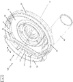
- An inventive angle grinder dust hood 100 is in Fig. 1 shown in a plan view.
- the angle grinder dust hood 100 has a hood body 10 for covering a circular grinding wheel not shown in the figures. An axis of rotation R of the grinding wheel is indicated by a dot-dash line.
- the angle grinder dust hood 100 likewise has a hood segment 20 which is displaceable along a circumferential direction N of the hood body 10 along the hood body 10.
- the hood body 10 is configured to cover a majority of the grinding wheel, with the sliding hood segment 20 being provided for covering and releasing a remaining portion of the grinding wheel.
- the hood body 10 and the sliding hood segment 20 each have a sealing member 30 in the form of a brush curtain.
- the sealing element 30 is positioned in a first retaining rail 31 and in a second retaining rail 31 '.
- the brush curtain 30 is formed in two parts or two brush curtains are provided.
- the designed as a brush curtain sealing member 30 for the hood body 10 is clamped or positioned in the first retaining rail 31.
- the sealing element 30 designed as a brush curtain for the hood segment 20 is clamped or positioned in the second retaining rail 31 '.
- the brush curtains 30 serve to seal the hood body 10 and the hood segment 20 to a machined surface of a material, which is not shown here.
- a surface removal in the course of processing (for example grinding work) can be sucked off via a suction connection 40 provided on the hood body 10.
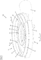
- the brush curtain 30 is spring-loaded with respect to the hood body 10 and the hood segment 20 in the axial direction, relative to the axis of rotation R of the grinding wheel, by a spring element 50.
- the spring element 50 is in a first embodiment in Fig. 6 and in a second embodiment in FIG Fig. 7 shown isolated.
- the spring element 50 has a flat base web 51, by way of which the spring element 50 is fastened to the hood body or hood segment 20.
- the spring element 50 via a pin (see FIG. Fig. 2 ) (eg hot-caulked), the pin engaging in a hole 52.
- FIG. 7 illustrated second embodiment of the spring element 50 substantially corresponds to the first embodiment.
- the base web 51 has no hole.
- the spring element 50 has two projecting from the base web 51 in opposite directions spring wings 53.
- the spring wings 53 each exert a spring action on a retaining rail 31 of the brush curtain 30.
- the spring wings 53 are oriented with the spring element 50 mounted in the direction of the outer circumferential direction N of the hood body 10.
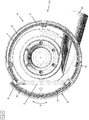
- the first support rail 31 for the sealing element 30 extends along a closed circumference U to the hood body 10.
- the circumference U extends along a circular arc A of the hood body 10 and a chord D of the hood segment 20.
- the first support rail 31 is substantially a closed Circle with a straight side, namely the circular chord D of the hood segment 20.
- the sealing member 30 is for the hood body 10 only in the support rail 31 along the arc A of the hood body 10.
- the portion of the support rail 31 along the chord D of the hood segment 20 has no sealing member 30.
- the retaining rail 31 'for receiving the sealing member 30 for the hood segment 20 extends along the circular arc B of the hood segment 20 and the chord D of the hood segment 20.
- the sealing member 30 is located only in the portion of the support rail 31' along the arc B of the hood segment 20th ,
- hood segment 20 When the angle grinder hood 100 is as in Fig. 4 shown in a closed state (ie, hood segment 20 is closed), closes the sealing member 30 for the hood segment 20, the portion of the support rail 31 along the chord D of the hood segment 20, which has no sealing member 30.
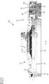
- the hood body 10 and the hood segment 20 have retaining clips 55 which are designed to prevent an axial fall-out of the brush curtain 30 from the hood body 10 or the hood segment 20.
- the headband 55 protrudes in the axial direction from the bottom of the hood body 10 and instructs its free end a stop for the retaining rail 31, 31 'of the brush curtain 30 on.
- the axial stop is presently designed as a stop web 57 which extends substantially parallel to the hood body 10.
- the retaining bracket 55 is deflectable in the radial direction to the rotation axis R, indicated by the double arrow M, for the purpose of replacing the brush curtain.
- a brush curtain sealing member 30 can be replaced without a special tool is required for it.
- the hood body 10 has a central opening 11, through which a drive spindle, not shown here, to which the circular grinding wheel is to be attached, can protrude through the central opening 11.
- a groove 12 is formed, so that the hood body 10 can be positively secured and thus fixed to a frame fixed to an angle grinder, not shown.
- spring elements 50 exert by their respective spring wings 53 a spring action on the support rail 31 of the brush curtain 30.
Landscapes
- Engineering & Computer Science (AREA)
- Mechanical Engineering (AREA)
- Grinding-Machine Dressing And Accessory Apparatuses (AREA)
- Finish Polishing, Edge Sharpening, And Grinding By Specific Grinding Devices (AREA)
Priority Applications (5)
| Application Number | Priority Date | Filing Date | Title |
|---|---|---|---|
| EP16156035.4A EP3208040A1 (fr) | 2016-02-17 | 2016-02-17 | Meuleuse d'angle a collecteur de poussieres |
| US16/075,718 US20190039207A1 (en) | 2016-02-17 | 2017-02-14 | Dust collector for angle grinder |
| CN201780011429.2A CN108698200B (zh) | 2016-02-17 | 2017-02-14 | 角磨机防尘罩 |
| EP17704030.0A EP3416780B1 (fr) | 2016-02-17 | 2017-02-14 | Meuleuse d'angle a collecteur de poussieres |
| PCT/EP2017/053240 WO2017140655A1 (fr) | 2016-02-17 | 2017-02-14 | Collecteur de poussière de meuleuse d'angle |
Applications Claiming Priority (1)
| Application Number | Priority Date | Filing Date | Title |
|---|---|---|---|
| EP16156035.4A EP3208040A1 (fr) | 2016-02-17 | 2016-02-17 | Meuleuse d'angle a collecteur de poussieres |
Publications (1)
| Publication Number | Publication Date |
|---|---|
| EP3208040A1 true EP3208040A1 (fr) | 2017-08-23 |
Family
ID=55361408
Family Applications (2)
| Application Number | Title | Priority Date | Filing Date |
|---|---|---|---|
| EP16156035.4A Withdrawn EP3208040A1 (fr) | 2016-02-17 | 2016-02-17 | Meuleuse d'angle a collecteur de poussieres |
| EP17704030.0A Active EP3416780B1 (fr) | 2016-02-17 | 2017-02-14 | Meuleuse d'angle a collecteur de poussieres |
Family Applications After (1)
| Application Number | Title | Priority Date | Filing Date |
|---|---|---|---|
| EP17704030.0A Active EP3416780B1 (fr) | 2016-02-17 | 2017-02-14 | Meuleuse d'angle a collecteur de poussieres |
Country Status (4)
| Country | Link |
|---|---|
| US (1) | US20190039207A1 (fr) |
| EP (2) | EP3208040A1 (fr) |
| CN (1) | CN108698200B (fr) |
| WO (1) | WO2017140655A1 (fr) |
Families Citing this family (5)
| Publication number | Priority date | Publication date | Assignee | Title |
|---|---|---|---|---|
| EP3812089A1 (fr) | 2019-10-23 | 2021-04-28 | Black & Decker Inc. | Ponceuse à manche |
| EP4289552A1 (fr) | 2019-10-23 | 2023-12-13 | Black & Decker, Inc. | Ponceuse à bâton |
| EP4592034A3 (fr) | 2019-10-23 | 2025-10-22 | Black & Decker, Inc. | Ponceuse à bâton |
| EP3812091B1 (fr) * | 2019-10-23 | 2023-05-10 | Black & Decker Inc. | Ponceuse à manche |
| US11867224B2 (en) | 2021-01-27 | 2024-01-09 | Black & Decker Inc. | Locking mechanism for two telescoping poles of a power tool |
Citations (9)
| Publication number | Priority date | Publication date | Assignee | Title |
|---|---|---|---|---|
| WO2008033377A2 (fr) * | 2006-09-12 | 2008-03-20 | Black & Decker Inc. | Outil de ponçage avec ensemble de tête couplé par pivotement |
| US20090181605A1 (en) * | 2008-01-15 | 2009-07-16 | Michael Loveless | Dust shroud with adjustable mounting mechanism |
| EP2163356A2 (fr) * | 2008-09-12 | 2010-03-17 | Protool GmbH | Machine-outil manuel dotée d'un capot de recouvrement et d'un raccordement d'évacuation de poussière |
| EP2186600A1 (fr) * | 2008-11-12 | 2010-05-19 | Collomix Rühr-und Mischgeräte GmbH | Dispositif de ponçage de surface, notamment un dispositif de ponçage de béton |
| EP2202029A2 (fr) * | 2008-12-23 | 2010-06-30 | Flex-Elektrowerkzeuge GmbH | Tête de support d'outil pour une machine de nettoyage/affilage manuelle et machine de nettoyage/affilage manuelle |
| US20100261417A1 (en) * | 2002-12-23 | 2010-10-14 | O'shannessy Peter | Hand tool support and dust shroud |
| EP2479001A1 (fr) * | 2011-01-19 | 2012-07-25 | Hitachi Koki Co., Ltd. | Adaptateur de collecte de poussière et outil électrique incluant l'adaptateur de collecte de poussière |
| EP2527089A1 (fr) * | 2011-05-27 | 2012-11-28 | Robert Bosch Gmbh | Appareil de meulage manuel motorisé |
| WO2014086873A1 (fr) * | 2012-12-07 | 2014-06-12 | Flex-Elektrowerkzeuge Gmbh | Meuleuse à main |
-
2016
- 2016-02-17 EP EP16156035.4A patent/EP3208040A1/fr not_active Withdrawn
-
2017
- 2017-02-14 CN CN201780011429.2A patent/CN108698200B/zh active Active
- 2017-02-14 EP EP17704030.0A patent/EP3416780B1/fr active Active
- 2017-02-14 US US16/075,718 patent/US20190039207A1/en not_active Abandoned
- 2017-02-14 WO PCT/EP2017/053240 patent/WO2017140655A1/fr not_active Ceased
Patent Citations (9)
| Publication number | Priority date | Publication date | Assignee | Title |
|---|---|---|---|---|
| US20100261417A1 (en) * | 2002-12-23 | 2010-10-14 | O'shannessy Peter | Hand tool support and dust shroud |
| WO2008033377A2 (fr) * | 2006-09-12 | 2008-03-20 | Black & Decker Inc. | Outil de ponçage avec ensemble de tête couplé par pivotement |
| US20090181605A1 (en) * | 2008-01-15 | 2009-07-16 | Michael Loveless | Dust shroud with adjustable mounting mechanism |
| EP2163356A2 (fr) * | 2008-09-12 | 2010-03-17 | Protool GmbH | Machine-outil manuel dotée d'un capot de recouvrement et d'un raccordement d'évacuation de poussière |
| EP2186600A1 (fr) * | 2008-11-12 | 2010-05-19 | Collomix Rühr-und Mischgeräte GmbH | Dispositif de ponçage de surface, notamment un dispositif de ponçage de béton |
| EP2202029A2 (fr) * | 2008-12-23 | 2010-06-30 | Flex-Elektrowerkzeuge GmbH | Tête de support d'outil pour une machine de nettoyage/affilage manuelle et machine de nettoyage/affilage manuelle |
| EP2479001A1 (fr) * | 2011-01-19 | 2012-07-25 | Hitachi Koki Co., Ltd. | Adaptateur de collecte de poussière et outil électrique incluant l'adaptateur de collecte de poussière |
| EP2527089A1 (fr) * | 2011-05-27 | 2012-11-28 | Robert Bosch Gmbh | Appareil de meulage manuel motorisé |
| WO2014086873A1 (fr) * | 2012-12-07 | 2014-06-12 | Flex-Elektrowerkzeuge Gmbh | Meuleuse à main |
Also Published As
| Publication number | Publication date |
|---|---|
| EP3416780A1 (fr) | 2018-12-26 |
| EP3416780B1 (fr) | 2019-10-23 |
| CN108698200A (zh) | 2018-10-23 |
| WO2017140655A1 (fr) | 2017-08-24 |
| US20190039207A1 (en) | 2019-02-07 |
| CN108698200B (zh) | 2020-06-09 |
Similar Documents
| Publication | Publication Date | Title |
|---|---|---|
| EP3416780B1 (fr) | Meuleuse d'angle a collecteur de poussieres | |
| EP1819481B1 (fr) | Dispositif pour operations de separation et de polissage, dispositif de fixation et outil rotatif, a amortissement de vibrations | |
| EP3658336B1 (fr) | Dispositif de retenu à crochets pour une machine-outil | |
| DE102007041840A1 (de) | Handwerkzeugmaschine mit Schutzhaube, insbesondere Winkelschleifer | |
| DE202011051408U1 (de) | Handgehaltenes Kraftwerkzeug mit einer Schnellspannvorrichtung für ein Arbeitselement | |
| CH660141A5 (de) | Stativbohrgeraet. | |
| EP3416779B1 (fr) | Meuleuse d'angle a collecteur de poussieres | |
| CH404443A (de) | Für die Schleifscheibe einer motorisch angetriebenen Handschleifmaschine bestimmte Schutzhaube | |
| DE10317709B4 (de) | Umlenkvorrichtung für einen Sicherheitsgurt | |
| DE212006000058U1 (de) | Handhabungswerkzeug für Verglasungen | |
| DE102013220202B4 (de) | Absaugvorrichtung für eine Werkzeugmaschine | |
| EP1782918B1 (fr) | Dispositif de serrage pour une meule, meule et élément porteur d'une meule | |
| DE716035C (de) | Staubsaugende Bohnermaschine | |
| DE7823882U1 (de) | Montagevorrichtung fuer schleifblaetter | |
| EP3210494A1 (fr) | Systeme de fixation pour elements renverses | |
| DE102019102845B4 (de) | Zwei elastische Ringkörper aufweisende Drehachsenanordnung für eine Lenkrolle | |
| DE10003504C2 (de) | Handschleifgerät | |
| EP2829340B1 (fr) | Dispositif de serrage | |
| DE1917402A1 (de) | Maschine zum Schmirgeln von Waenden od.dgl. | |
| DE202019100668U1 (de) | Zwei elastische Ringkörper aufweisende Drehachsenanordnung für eine Lenkrolle | |
| EP0510133A1 (fr) | Outil rotatif | |
| WO2007026007A1 (fr) | Dispositif pour separer et polir, dispositif de serrage et outil a amortissement de vibrations | |
| EP4219073A1 (fr) | Dispositif outil rotatif à entraînement rotatif | |
| DE102006025068A1 (de) | Sägeblatt mit Abdeckung für Oszillationsantrieb | |
| DE102016221406B4 (de) | Reinigungsvorrichtung |
Legal Events
| Date | Code | Title | Description |
|---|---|---|---|
| PUAI | Public reference made under article 153(3) epc to a published international application that has entered the european phase |
Free format text: ORIGINAL CODE: 0009012 |
|
| AK | Designated contracting states |
Kind code of ref document: A1 Designated state(s): AL AT BE BG CH CY CZ DE DK EE ES FI FR GB GR HR HU IE IS IT LI LT LU LV MC MK MT NL NO PL PT RO RS SE SI SK SM TR |
|
| AX | Request for extension of the european patent |
Extension state: BA ME |
|
| STAA | Information on the status of an ep patent application or granted ep patent |
Free format text: STATUS: THE APPLICATION IS DEEMED TO BE WITHDRAWN |
|
| 18D | Application deemed to be withdrawn |
Effective date: 20180224 |