EP2202127A2 - Bogie de véhicule ferroviaire - Google Patents
Bogie de véhicule ferroviaire Download PDFInfo
- Publication number
- EP2202127A2 EP2202127A2 EP09251097A EP09251097A EP2202127A2 EP 2202127 A2 EP2202127 A2 EP 2202127A2 EP 09251097 A EP09251097 A EP 09251097A EP 09251097 A EP09251097 A EP 09251097A EP 2202127 A2 EP2202127 A2 EP 2202127A2
- Authority
- EP
- European Patent Office
- Prior art keywords
- bogie
- transoms
- side beams
- air spring
- spring bearing
- Prior art date
- Legal status (The legal status is an assumption and is not a legal conclusion. Google has not performed a legal analysis and makes no representation as to the accuracy of the status listed.)
- Granted
Links
Images


Classifications
-
- B—PERFORMING OPERATIONS; TRANSPORTING
- B61—RAILWAYS
- B61F—RAIL VEHICLE SUSPENSIONS, e.g. UNDERFRAMES, BOGIES OR ARRANGEMENTS OF WHEEL AXLES; RAIL VEHICLES FOR USE ON TRACKS OF DIFFERENT WIDTH; PREVENTING DERAILING OF RAIL VEHICLES; WHEEL GUARDS, OBSTRUCTION REMOVERS OR THE LIKE FOR RAIL VEHICLES
- B61F5/00—Constructional details of bogies; Connections between bogies and vehicle underframes; Arrangements or devices for adjusting or allowing self-adjustment of wheel axles or bogies when rounding curves
- B61F5/50—Other details
- B61F5/52—Bogie frames
-
- B—PERFORMING OPERATIONS; TRANSPORTING
- B61—RAILWAYS
- B61F—RAIL VEHICLE SUSPENSIONS, e.g. UNDERFRAMES, BOGIES OR ARRANGEMENTS OF WHEEL AXLES; RAIL VEHICLES FOR USE ON TRACKS OF DIFFERENT WIDTH; PREVENTING DERAILING OF RAIL VEHICLES; WHEEL GUARDS, OBSTRUCTION REMOVERS OR THE LIKE FOR RAIL VEHICLES
- B61F5/00—Constructional details of bogies; Connections between bogies and vehicle underframes; Arrangements or devices for adjusting or allowing self-adjustment of wheel axles or bogies when rounding curves
- B61F5/02—Arrangements permitting limited transverse relative movements between vehicle underframe or bolster and bogie; Connections between underframes and bogies
- B61F5/04—Bolster supports or mountings
- B61F5/10—Bolster supports or mountings incorporating fluid springs
-
- B—PERFORMING OPERATIONS; TRANSPORTING
- B61—RAILWAYS
- B61H—BRAKES OR OTHER RETARDING DEVICES SPECIALLY ADAPTED FOR RAIL VEHICLES; ARRANGEMENT OR DISPOSITION THEREOF IN RAIL VEHICLES
- B61H5/00—Applications or arrangements of brakes with substantially radial braking surfaces pressed together in axial direction, e.g. disc brakes
Definitions
- the present invention relates to a bogie of a railway vehicle comprising a bogie frame having a structure in which transoms arranged in the direction of sleepers are passed through the longitudinal centre portion of side beams arranged in the direction of the rails, capable of reducing the stress applied to the welded portion between brake gear attachments and the transoms, and promoting weight reduction and improved operability by reducing the number of components constituting the bogie frame.
- the prior art bogie frames of railway vehicles generally adopt an H-shaped structure including two side beams arranged in the direction of the rails and two transoms passing through the longitudinal centre portion of the side beams in the direction of sleepers.
- the transoms constituting the bogie frame are formed of steel pipes, and main motor attachments for attaching main motors are welded to the longitudinal centre portion of the transoms, and brake gear attachments for attaching brake gears are welded to the transoms at positions corresponding to the wheels.
- the brake gear attachments are attached via welding to transoms at positions corresponding to the wheels.
- air spring bearing racks for placing air springs are positioned so that their longitudinal directions correspond to the longitudinal direction of the side beams, and attached via welding to both ends of the two transoms protruded through the side beams in the direction of the sleepers in such a manner as to connect both ends of the transoms.
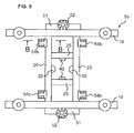
- FIGS. 8 and 9 show upper views of a prior art bogie 1b and a bogie frame 5b.
- the prior art bogie 1b of a railway vehicle shown in FIG. 8 has longitudinal ends of side beams 10 constituting the bogie frame 5b arranged at both ends of axles 230 and 230 passed through and protruding from the wheels 240 and 240.
- the side beams 10 are arranged in parallel on either sides of a track centre 500.
- two transoms 20 and 20 are passed through the longitudinal centre portion of the side beams 10 and 10 spaced apart and arranged in parallel.
- two tie beams 25 and 25 arranged in the direction of the rails are disposed to connect the transoms 20 and 20.
- the side beams 10 and 10 and the transoms 20 and 20 are connected via welding, and the transoms 20 and 20 and the tie beams 25 and 25 are connected via welding.
- Longitudinal bumpstop brackets 30 and 30 are provided on the transoms 20 and 20, and similarly, lateral bumpstop brackets 40 and 40 are arranged on the tie beams 25 and 25, so as to protrude toward the space surrounded by the transoms 20 and 20 and the tie beams 25 and 25.
- a traction beam (not shown) attached to a centre pin provided on the vehicle body and link brackets (not shown) provided on the transoms 20 and 20 are connected via a longitudinal link (not shown) in the direction of the rails (longitudinal direction) of the vehicle body.
- the longitudinal bumpstop brackets 30 and 30 support the centre pin directly.
- the centre pin and lateral movement damper brackets (not shown) provided on the side beams 10 and 10 are connected via a lateral movement damper (not shown). Only when a large lateral displacement exceeding the specification of the lateral movement damper occurs, the lateral bumpstop brackets 40 and 40 support the centre pin directly.
- the lateral movement damper suppresses the relative displacement in the lateral direction of the vehicle body and the bogie 1a caused by track irregularity when the vehicle is travelling at high speed.
- brake gear attachments 54b are attached to welding portions 160b in a cantilever structure at positions corresponding to wheels 240 on transoms 20 and 20 at the track-centre 500 side of side beams 10 and 10.
- the brake gear attachments 54b have brake gears 56 attached thereto for generating brake force to wheels 240 through friction engagement with wheels 240.
- Each brake gear attachment 54b is composed of an upper panel 120, a lower panel 130 and a side panel 110.
- the welding portion 160b is formed in the circumference of the transom 20 at a side facing the side panel 110 at an angular range of approximately 180 degrees, for example, as shown.
- each air spring bearing rack 51 is disposed at the centre portion of each air spring bearing rack 51 having holes arranged annularly for reducing the weight thereof.
- Reference number 200 denotes a yaw damper for suppressing yawing (vibration within a horizontal plane having the bogie centre pin (not shown) arranged at the centre of rotation) of the bogie.
- each brake gear attachment 54b is generally joined via welding to the side surface of the transom 20 in a cantilever structure. Therefore, when the brake is operated, the moment load based on the brake force in the tangential direction of the rotating wheels 240 (the force in the longitudinal direction of the paper plane of FIG. 10 ) and the length of the brake gear 56 (length of the brake gear attachment 54b in the rail direction, which is the lateral direction of the paper plane of FIG. 9 ) was applied on the welding portion 160b between the brake gear attachment 54b and the transom 20, so that high stress was applied on the welding portion 160b and on the respective components surrounding the same.
- the moment load is applied in the direction separating the welding portion 160b, that is, in the direction separating the brake gear attachment 54b from the transom 20.
- the plate thickness of the brake gear attachment 54b was increased, there was a drawback in that the mass of the bogie frame 5b was also increased.
- the brake gear attachments 54b and the air spring bearing racks 51 are formed as individual components, the number of components constituting the bogie frame tends to be excessive. Furthermore, since such individual components were fixed via welding to the transoms 20 constituting the bogie frame 5b, the amount of welding became excessive, and thus, the number of processes such as the processing of grooves and the welding operation became excessive.
- the present invention aims at solving the problems of the prior art by providing a bogie of a railway vehicle capable of reducing the number of processes by revising the design of the brake gear attachments and the air spring bearing racks, the attachment structure thereof to the bogie frame, reducing the number of components constituting the bogie frame and reducing the amount of welding required to attach these components to the bogie frame. Further, by improving the structure for fixing the brake gear attachments to the transoms, it becomes possible to provide a bogie of a railway vehicle capable of reducing the stress applied on the joint (welding portion) between the brake gear attachments and the transoms during brake operation without increasing the mass of the brake gear attachments.
- the present invention provides a bogie of a railway vehicle having disposed on a bogie frame including two side beams arranged in parallel and spaced apart and side beams passing through longitudinal centre portions of the side beams, a wheel set having wheels disposed on both ends of an axle, brakes for generating brake force to the wheels, air springs supporting a weight of the vehicle body, and air spring bearing racks arranged on the transoms having air springs attached to a longitudinal centre portion thereof; characterized in that the air spring bearing racks have brake attachments for attaching the brakes provided integrally to both ends thereof.
- the present invention provides a bogie of a railway vehicle mentioned above, wherein the air spring bearing racks are disposed so that their longitudinal direction corresponds to a longitudinal direction of the side beams, and are arranged at both ends of the transoms passing through the side beams and protruded toward an opposite side from a track-centre side of the side beams.
- the bogie of a railway vehicle mentioned above is characterized in that the side beams are disposed on a track-centre side than the wheels.
- the bogie of a railway vehicle mentioned above is characterized in that lateral bumpstop brackets are provided at the track-centre side of the longitudinal centre portion of the side beams near a centre pin extending downward from the vehicle body.
- the bogie of a railway vehicle mentioned above can be characterized in that the transoms function as an auxiliary air reservoir for the air springs.
- a bogie of a railway vehicle comprises air spring bearing racks having brake gear attachments provided integrally thereto, so as to reduce the stress applied on the mounting portions where the brake gear attachments were attached to the transoms, to reduce the weight of the bogie and to promote further reduction of work load due to the reduction in the number of components constituting the bogie.
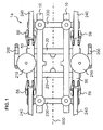
- a bogie 1a of a railway vehicle illustrated in FIG. 1 is an inner frame-type bogie having two wheel sets including wheels 240 arranged on both ends of each axle 230, and side beams 10 constituting a bogie frame 5a disposed on a track-centre 500 side (inner side) than the wheels 240.
- the bogie frame 5a is composed of side beams 10 and 10 arranged in parallel and spaced apart from each other, air spring bearing racks 50 and 50 longitudinally arranged in parallel with the side beams 10 and 10 at the outer sides of the side beams 10 and 10 (in the direction opposite from the track centre 500), and transoms 20 and 20 passed through the side beams 10 and 10 and air spring bearing racks 50 and 50 at the longitudinal centre area thereof.
- the side beams 10 and 10, the air spring bearing racks 50 and 50 and the transoms 20 and 20 are respectively joined together via welding.
- the shape of the bogie frame 5a in overhead view is H-shaped.
- Air springs 210 are attached via air spring seats 52 on the upper surface at the longitudinal centre portion of the air spring bearing racks 50, and the air springs 210 support the weight of the car body (not shown).
- yaw dampers 200 are disposed in a manner so as to connect the car body (not shown) and yaw damper brackets 58 arranged on the side surface at the centre of the air spring bearing racks 50.
- Brake gear attachments 54a and 54a for fixing brake gears 56 and 56 are integrally disposed at both longitudinal ends of the respective air spring bearing racks 50.
- each brake gear 56 nips brake disks (not shown) arranged on both side surfaces of the wheel 240 with a brake shoe (not shown).
- Brake force is generated by the frictional force generated between the brake shoe and the brake disks during braking.
- the brake gear 56 adopts a disk brake system in which the brake shoe is sandwiched between disks arranged on both sides of the wheel 240, but the brake gear 56 can also adopt a wheel tread brake system in which a brake shoe is pressed against a wheel tread (the portion rotating on the top part of the rail) of the wheel 240.
- longitudinal bumpstop brackets 30 and 30 and lateral bumpstop brackets 40 and 40 are disposed to protrude in the space surrounded by the side beams 10 and 10 and the transoms 20 and 20.
- a centre pin (not shown) is disposed vertically downward toward the direction of the sleeper at the centre of the lower surface of the car body positioned above the bogie 1a. When the car body is placed on the bogie 1a, the centre pin is positioned in the space defined by the side beams 10 and 10 and the transoms 20 and 20.
- a traction beam disposed on the centre pin and a longitudinal link bracket disposed on the transom are connected via a longitudinal link. Only when a load exceeding the withstand load of the longitudinal link acts on the car body, the longitudinal bumpstop brackets 30 and 30 support the centre pin directly.
- the centre pin and a lateral movement stopper bracket disposed on the side beams 10 and 10 are connected via a lateral movement damper. Only when a lateral displacement exceeding the specification of the lateral movement damper occurs, the lateral bumpstop brackets 40 and 40 support the centre pin directly.
- the lateral movement damper suppresses the relative displacement of the car body and the bogie 1a caused by rail track irregularity when the vehicle is running at high speed.
- the transoms 20 and 20 are composed of pipes, but the transoms 20 and 20 can also be box-shaped in which four sides of panel members are joined together.
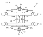
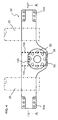
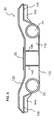
- FIGS. 4 through 7 illustrate the structure of an air spring bearing rack 50.
- the air spring bearing rack 50 has a four-sided structure (box-shaped structure) in which an upper panel 120, a lower panel 130 and side panels 110 are joined together via welding.
- Brake gear attachments 54a and 54a are integrally formed at both longitudinal ends of the air spring bearing rack 50.
- each brake gear 56 is secured to the brake gear attachment 54a via bolts.
- the method for securing the brake gear 56 to the brake gear attachment 54a is not restricted to the aforementioned engagement method using bolts, and for example, the brake gear 56 can be secured to the brake gear attachment 54a by assembling together key structures respectively provided to the mounting surfaces of the brake gear attachment 54a and the brake gear 56.
- An air spring seat 52 is provided at the centre area of the air spring bearing rack 50 for fixing the air spring 210.
- the air spring seat 52 has holes formed thereto for reducing the weight thereof. Since the weight of the car body is supported by the air spring 210, a large perpendicular-direction load is applied to the centre portion of the air spring bearing rack 50 via the air spring seat 52. Therefore, a plurality of reinforcements 140 are provided at the centre portion of the air spring bearing rack 50 so as to ensure sufficient strength to correspond to such large load.
- the prior art brake gear attachments 54b according to FIG. 10 were attached via welding (welding portions 160b) to the transoms 20 in a cantilever structure.
- the air spring bearing racks 50 according to the present embodiment are fixed via welding (welding portions 160a) to both ends of the transoms 20 and 20 in such a manner as to cross over both ends of the transoms 20 and 20 from above.
- the present embodiment provides brake gear attachments 54a and 54a integrally to both longitudinal ends of the air spring bearing racks 50.
- each welding portion 160a is formed to surround a large area, such as over 180 degrees, of the transoms 20, no excessive stress is applied on the welding portions 160a even when a moment load is applied on the brake gear attachments 54a. Therefore, according to the stress reduction effect of the bogie 1a of the present invention, it becomes possible to cut down the number of steps for smoothly finishing the welding portions 160a between the air spring bearing racks 50 having brake gear attachments and the transoms 20 and 20.
- the air spring bearing racks 50 can be attached so as to pass through both ends of the transoms 20 and 20. According to such attachment method, the welding can be performed to cover the whole circumference of the welding portion between the transoms 20 and 20 and the air spring bearing rack 50, so that the strength of the attached portion can be further enhanced.
Landscapes
- Engineering & Computer Science (AREA)
- Mechanical Engineering (AREA)
- Braking Arrangements (AREA)
- Vibration Prevention Devices (AREA)
Applications Claiming Priority (1)
| Application Number | Priority Date | Filing Date | Title |
|---|---|---|---|
| JP2008332806A JP4685921B2 (ja) | 2008-12-26 | 2008-12-26 | 鉄道車両用台車 |
Publications (3)
| Publication Number | Publication Date |
|---|---|
| EP2202127A2 true EP2202127A2 (fr) | 2010-06-30 |
| EP2202127A3 EP2202127A3 (fr) | 2011-03-30 |
| EP2202127B1 EP2202127B1 (fr) | 2015-07-22 |
Family
ID=42101269
Family Applications (1)
| Application Number | Title | Priority Date | Filing Date |
|---|---|---|---|
| EP09251097.3A Active EP2202127B1 (fr) | 2008-12-26 | 2009-04-15 | Bogie de véhicule ferroviaire |
Country Status (2)
| Country | Link |
|---|---|
| EP (1) | EP2202127B1 (fr) |
| JP (1) | JP4685921B2 (fr) |
Cited By (23)
| Publication number | Priority date | Publication date | Assignee | Title |
|---|---|---|---|---|
| CN102923152A (zh) * | 2011-08-10 | 2013-02-13 | 南车青岛四方机车车辆股份有限公司 | 轻量化转向架焊接构架及其焊接加工方法 |
| CN103693064A (zh) * | 2013-12-05 | 2014-04-02 | 南车眉山车辆有限公司 | 一种用于快速铁路货车转向架的构架 |
| CN103863347A (zh) * | 2014-04-02 | 2014-06-18 | 成都市新筑路桥机械股份有限公司 | 一种用于100%低地板有轨电车的二系沙漏簧悬挂装置 |
| CN103879426A (zh) * | 2014-04-02 | 2014-06-25 | 成都市新筑路桥机械股份有限公司 | 一种用于100%低地板有轨电车的二系高圆簧悬挂装置 |
| CN103935379A (zh) * | 2014-04-02 | 2014-07-23 | 成都市新筑路桥机械股份有限公司 | 一种100%低地板轻轨列车非动力转向架构架 |
| CN105313913A (zh) * | 2015-11-23 | 2016-02-10 | 长春轨道客车股份有限公司 | 超高速试验动车组转向架 |
| CN105313914A (zh) * | 2015-11-23 | 2016-02-10 | 长春轨道客车股份有限公司 | 超高速动车组转向架弹性构架 |
| CN105880893A (zh) * | 2016-05-31 | 2016-08-24 | 俞升洋 | 一种焊接装置 |
| CN105965188A (zh) * | 2016-05-31 | 2016-09-28 | 俞升洋 | 焊缝焊接车 |
| CN105965186A (zh) * | 2016-05-31 | 2016-09-28 | 俞升洋 | 一种移动焊接装置 |
| CN105965187A (zh) * | 2016-05-31 | 2016-09-28 | 俞升洋 | 一种工厂车间用焊接车 |
| CN108032865A (zh) * | 2017-12-19 | 2018-05-15 | 中车株洲电力机车有限公司 | 一种横向驱动的轴箱内置式转向架 |
| CN108032864A (zh) * | 2017-12-19 | 2018-05-15 | 中车株洲电力机车有限公司 | 一种纵向驱动的轴箱内置式转向架 |
| CN108045397A (zh) * | 2017-12-19 | 2018-05-18 | 中车株洲电力机车有限公司 | 一种轴箱内置式转向架用构架 |
| CN110337398A (zh) * | 2017-02-23 | 2019-10-15 | 川崎重工业株式会社 | 铁道车辆用转向架构架及具备该铁道车辆用转向架构架的转向架 |
| CN112622971A (zh) * | 2021-01-05 | 2021-04-09 | 中车唐山机车车辆有限公司 | 构架、转向架及轨道车辆 |
| CN112644548A (zh) * | 2019-10-10 | 2021-04-13 | 中车唐山机车车辆有限公司 | 一种转向架的构架 |
| WO2022032809A1 (fr) * | 2020-08-14 | 2022-02-17 | 中车唐山机车车辆有限公司 | Véhicule ferroviaire |
| CN114084184A (zh) * | 2021-09-26 | 2022-02-25 | 中车青岛四方机车车辆股份有限公司 | 构架以及转向架、轨道车辆 |
| EP3992053A1 (fr) * | 2020-10-27 | 2022-05-04 | Stadler Rail AG | Bogie de véhicule ferroviaire et véhicule ferroviaire doté d'un bogie |
| EP4008599A4 (fr) * | 2019-08-02 | 2023-01-11 | Crrc Tangshan Co., Ltd. | Bogie et véhicule ferroviaire |
| EP4008601A4 (fr) * | 2019-08-02 | 2023-01-11 | Crrc Tangshan Co., Ltd. | Bogie et véhicule ferroviaire |
| CN119190111A (zh) * | 2024-10-22 | 2024-12-27 | 中车青岛四方机车车辆股份有限公司 | 一种轴箱内置转向架及轨道车辆 |
Families Citing this family (9)
| Publication number | Priority date | Publication date | Assignee | Title |
|---|---|---|---|---|
| CN104691569A (zh) * | 2013-12-05 | 2015-06-10 | 南车青岛四方机车车辆股份有限公司 | 转向架及其构架 |
| CN103770805B (zh) * | 2013-12-27 | 2017-02-08 | 中车青岛四方机车车辆股份有限公司 | 拖车转向架 |
| JP6556487B2 (ja) * | 2015-04-24 | 2019-08-07 | 日本車輌製造株式会社 | 鉄道車両用台車 |
| EP3339130B1 (fr) * | 2015-08-19 | 2022-03-23 | Hitachi, Ltd. | Bogie pour véhicule ferroviaire |
| JP6564300B2 (ja) * | 2015-10-26 | 2019-08-21 | 日本車輌製造株式会社 | 鉄道車両用台車枠 |
| CN108045396B (zh) * | 2017-12-08 | 2019-12-13 | 中车大连机车车辆有限公司 | 宽轨地铁车辆轴箱内置式转向架构架 |
| DE202017107670U1 (de) * | 2017-12-18 | 2019-03-20 | Lothar Thoni | Drehgestellrahmen für Schienenfahrzeuge aus einem Aluminiumgussteil |
| JP7049898B2 (ja) * | 2018-04-16 | 2022-04-07 | 川崎車両株式会社 | 鉄道車両用台車枠 |
| CN113247089B (zh) * | 2021-06-07 | 2021-09-21 | 常州市新创智能科技有限公司 | 一种转向架构架及转向架 |
Citations (1)
| Publication number | Priority date | Publication date | Assignee | Title |
|---|---|---|---|---|
| JP2006015820A (ja) | 2004-06-30 | 2006-01-19 | Sumitomo Metal Ind Ltd | 鉄道車両用台車枠及び鉄道車両用台車 |
Family Cites Families (11)
| Publication number | Priority date | Publication date | Assignee | Title |
|---|---|---|---|---|
| DE494120C (de) * | 1930-03-19 | Buckeye Steel Castings Co | Laengstraeger fuer dreiachsige Drehgestelle | |
| GB191422259A (en) * | 1913-11-07 | 1915-07-08 | Walter Scott Adams | Improvements in Car Trucks. |
| US2250988A (en) * | 1939-07-19 | 1941-07-29 | Budd Wheel Co | Truck and brake arrangement therefor |
| US3570408A (en) * | 1968-10-30 | 1971-03-16 | Gen Steel Ind Inc | Bolsterless truck having pivotally connected side frame |
| JPH0784172B2 (ja) * | 1987-02-23 | 1995-09-13 | 株式会社日立製作所 | 連節車両 |
| JPH0686212B2 (ja) * | 1989-04-14 | 1994-11-02 | 株式会社日立製作所 | 鉄道車両用台車枠 |
| JP2965665B2 (ja) * | 1990-11-08 | 1999-10-18 | 富士重工業株式会社 | 鉄道車輌用台車枠 |
| IT1259517B (it) * | 1992-04-03 | 1996-03-20 | Fiat Ferroviaria Spa | Carrello per veicoli ferroviari ad alte prestazioni |
| JP3173255B2 (ja) * | 1993-11-05 | 2001-06-04 | 株式会社日立製作所 | 鉄道車両用台車 |
| FR2826328B1 (fr) * | 2001-06-26 | 2003-08-29 | Alstom | Bogie moteur pour vehicule ferroviaire a plancher bas integral |
| JP2008207576A (ja) * | 2007-02-23 | 2008-09-11 | Nippon Sharyo Seizo Kaisha Ltd | 鉄道車両用台車枠及びその製造方法 |
-
2008
- 2008-12-26 JP JP2008332806A patent/JP4685921B2/ja not_active Expired - Fee Related
-
2009
- 2009-04-15 EP EP09251097.3A patent/EP2202127B1/fr active Active
Patent Citations (1)
| Publication number | Priority date | Publication date | Assignee | Title |
|---|---|---|---|---|
| JP2006015820A (ja) | 2004-06-30 | 2006-01-19 | Sumitomo Metal Ind Ltd | 鉄道車両用台車枠及び鉄道車両用台車 |
Cited By (28)
| Publication number | Priority date | Publication date | Assignee | Title |
|---|---|---|---|---|
| CN102923152A (zh) * | 2011-08-10 | 2013-02-13 | 南车青岛四方机车车辆股份有限公司 | 轻量化转向架焊接构架及其焊接加工方法 |
| CN103693064A (zh) * | 2013-12-05 | 2014-04-02 | 南车眉山车辆有限公司 | 一种用于快速铁路货车转向架的构架 |
| CN103693064B (zh) * | 2013-12-05 | 2016-08-17 | 中车眉山车辆有限公司 | 一种用于快速铁路货车转向架的构架 |
| CN103935379B (zh) * | 2014-04-02 | 2016-04-27 | 成都市新筑路桥机械股份有限公司 | 一种100%低地板轻轨列车非动力转向架构架 |
| CN103863347A (zh) * | 2014-04-02 | 2014-06-18 | 成都市新筑路桥机械股份有限公司 | 一种用于100%低地板有轨电车的二系沙漏簧悬挂装置 |
| CN103879426A (zh) * | 2014-04-02 | 2014-06-25 | 成都市新筑路桥机械股份有限公司 | 一种用于100%低地板有轨电车的二系高圆簧悬挂装置 |
| CN103935379A (zh) * | 2014-04-02 | 2014-07-23 | 成都市新筑路桥机械股份有限公司 | 一种100%低地板轻轨列车非动力转向架构架 |
| CN105313914B (zh) * | 2015-11-23 | 2017-07-14 | 长春轨道客车股份有限公司 | 超高速动车组转向架弹性构架 |
| CN105313914A (zh) * | 2015-11-23 | 2016-02-10 | 长春轨道客车股份有限公司 | 超高速动车组转向架弹性构架 |
| CN105313913B (zh) * | 2015-11-23 | 2017-07-14 | 长春轨道客车股份有限公司 | 超高速试验动车组转向架 |
| CN105313913A (zh) * | 2015-11-23 | 2016-02-10 | 长春轨道客车股份有限公司 | 超高速试验动车组转向架 |
| CN105880893A (zh) * | 2016-05-31 | 2016-08-24 | 俞升洋 | 一种焊接装置 |
| CN105965188A (zh) * | 2016-05-31 | 2016-09-28 | 俞升洋 | 焊缝焊接车 |
| CN105965186A (zh) * | 2016-05-31 | 2016-09-28 | 俞升洋 | 一种移动焊接装置 |
| CN105965187A (zh) * | 2016-05-31 | 2016-09-28 | 俞升洋 | 一种工厂车间用焊接车 |
| CN110337398A (zh) * | 2017-02-23 | 2019-10-15 | 川崎重工业株式会社 | 铁道车辆用转向架构架及具备该铁道车辆用转向架构架的转向架 |
| CN108032864A (zh) * | 2017-12-19 | 2018-05-15 | 中车株洲电力机车有限公司 | 一种纵向驱动的轴箱内置式转向架 |
| CN108045397A (zh) * | 2017-12-19 | 2018-05-18 | 中车株洲电力机车有限公司 | 一种轴箱内置式转向架用构架 |
| CN108032865A (zh) * | 2017-12-19 | 2018-05-15 | 中车株洲电力机车有限公司 | 一种横向驱动的轴箱内置式转向架 |
| EP4008599A4 (fr) * | 2019-08-02 | 2023-01-11 | Crrc Tangshan Co., Ltd. | Bogie et véhicule ferroviaire |
| EP4008601A4 (fr) * | 2019-08-02 | 2023-01-11 | Crrc Tangshan Co., Ltd. | Bogie et véhicule ferroviaire |
| CN112644548A (zh) * | 2019-10-10 | 2021-04-13 | 中车唐山机车车辆有限公司 | 一种转向架的构架 |
| WO2022032809A1 (fr) * | 2020-08-14 | 2022-02-17 | 中车唐山机车车辆有限公司 | Véhicule ferroviaire |
| EP3992053A1 (fr) * | 2020-10-27 | 2022-05-04 | Stadler Rail AG | Bogie de véhicule ferroviaire et véhicule ferroviaire doté d'un bogie |
| US12325455B2 (en) | 2020-10-27 | 2025-06-10 | Stadler Rail Ag | Bogie for a rail vehicle and rail vehicle with a bogie |
| CN112622971A (zh) * | 2021-01-05 | 2021-04-09 | 中车唐山机车车辆有限公司 | 构架、转向架及轨道车辆 |
| CN114084184A (zh) * | 2021-09-26 | 2022-02-25 | 中车青岛四方机车车辆股份有限公司 | 构架以及转向架、轨道车辆 |
| CN119190111A (zh) * | 2024-10-22 | 2024-12-27 | 中车青岛四方机车车辆股份有限公司 | 一种轴箱内置转向架及轨道车辆 |
Also Published As
| Publication number | Publication date |
|---|---|
| JP4685921B2 (ja) | 2011-05-18 |
| EP2202127B1 (fr) | 2015-07-22 |
| EP2202127A3 (fr) | 2011-03-30 |
| JP2010149808A (ja) | 2010-07-08 |
Similar Documents
| Publication | Publication Date | Title |
|---|---|---|
| EP2202127B1 (fr) | Bogie de véhicule ferroviaire | |
| KR101707342B1 (ko) | 철도 차량의 대차 프레임 | |
| KR101956483B1 (ko) | 대차의 메인프레임과 가이드암이 일체로 형성된 모노레일 차량용 대차 | |
| EP4261098A1 (fr) | Système de bogie pour véhicule ferroviaire et véhicule ferroviaire | |
| GB2567545B (en) | Rail vehicle body structure | |
| JP6556487B2 (ja) | 鉄道車両用台車 | |
| JP2019123344A (ja) | 下部車体構造 | |
| JP6356342B2 (ja) | 軌条車両 | |
| CN107089242A (zh) | 铁道车辆用转向架 | |
| JP7163503B2 (ja) | 軌条車両 | |
| JP6178299B2 (ja) | 鉄道車両用台車及び鉄道車両 | |
| CN106080642B (zh) | 低地板轨道车辆转向架摇枕结构及转向架 | |
| JP2010042778A (ja) | 鉄道車両用台車 | |
| JP2006240482A (ja) | 鉄道車両の車体 | |
| JP2010254091A (ja) | 機関車車体構造 | |
| JP6509571B2 (ja) | 鉄道車両用台車 | |
| CN111232009B (zh) | 一种侧梁、构架和转向架 | |
| CN113184001A (zh) | 一种轨道车辆及其车体底架结构 | |
| KR101252547B1 (ko) | 철도차량용 현가장치 | |
| JP3534789B2 (ja) | 鉄道車両用台車枠 | |
| CN112424048B (zh) | 用于轨道车辆的轮组中间框架 | |
| CN115959166A (zh) | 一种守车转向架结构 | |
| JP3346347B2 (ja) | リニアモータを用いた鉄道車両用台車 | |
| WO2023281558A1 (fr) | Véhicule ferroviaire et procédé de production de ce dernier | |
| JPH09301163A (ja) | 車両用ボルスタレス台車 |
Legal Events
| Date | Code | Title | Description |
|---|---|---|---|
| PUAI | Public reference made under article 153(3) epc to a published international application that has entered the european phase |
Free format text: ORIGINAL CODE: 0009012 |
|
| 17P | Request for examination filed |
Effective date: 20090505 |
|
| AK | Designated contracting states |
Kind code of ref document: A2 Designated state(s): AT BE BG CH CY CZ DE DK EE ES FI FR GB GR HR HU IE IS IT LI LT LU LV MC MK MT NL NO PL PT RO SE SI SK TR |
|
| AX | Request for extension of the european patent |
Extension state: AL BA RS |
|
| PUAL | Search report despatched |
Free format text: ORIGINAL CODE: 0009013 |
|
| AK | Designated contracting states |
Kind code of ref document: A3 Designated state(s): AT BE BG CH CY CZ DE DK EE ES FI FR GB GR HR HU IE IS IT LI LT LU LV MC MK MT NL NO PL PT RO SE SI SK TR |
|
| AX | Request for extension of the european patent |
Extension state: AL BA RS |
|
| 17Q | First examination report despatched |
Effective date: 20130628 |
|
| GRAP | Despatch of communication of intention to grant a patent |
Free format text: ORIGINAL CODE: EPIDOSNIGR1 |
|
| INTG | Intention to grant announced |
Effective date: 20150305 |
|
| INTG | Intention to grant announced |
Effective date: 20150310 |
|
| GRAS | Grant fee paid |
Free format text: ORIGINAL CODE: EPIDOSNIGR3 |
|
| GRAA | (expected) grant |
Free format text: ORIGINAL CODE: 0009210 |
|
| AK | Designated contracting states |
Kind code of ref document: B1 Designated state(s): AT BE BG CH CY CZ DE DK EE ES FI FR GB GR HR HU IE IS IT LI LT LU LV MC MK MT NL NO PL PT RO SE SI SK TR |
|
| REG | Reference to a national code |
Ref country code: GB Ref legal event code: FG4D |
|
| REG | Reference to a national code |
Ref country code: CH Ref legal event code: EP |
|
| REG | Reference to a national code |
Ref country code: IE Ref legal event code: FG4D |
|
| REG | Reference to a national code |
Ref country code: AT Ref legal event code: REF Ref document number: 737705 Country of ref document: AT Kind code of ref document: T Effective date: 20150815 |
|
| REG | Reference to a national code |
Ref country code: DE Ref legal event code: R096 Ref document number: 602009032320 Country of ref document: DE |
|
| REG | Reference to a national code |
Ref country code: AT Ref legal event code: MK05 Ref document number: 737705 Country of ref document: AT Kind code of ref document: T Effective date: 20150722 |
|
| REG | Reference to a national code |
Ref country code: LT Ref legal event code: MG4D |
|
| REG | Reference to a national code |
Ref country code: NL Ref legal event code: MP Effective date: 20150722 |
|
| PG25 | Lapsed in a contracting state [announced via postgrant information from national office to epo] |
Ref country code: LT Free format text: LAPSE BECAUSE OF FAILURE TO SUBMIT A TRANSLATION OF THE DESCRIPTION OR TO PAY THE FEE WITHIN THE PRESCRIBED TIME-LIMIT Effective date: 20150722 Ref country code: FI Free format text: LAPSE BECAUSE OF FAILURE TO SUBMIT A TRANSLATION OF THE DESCRIPTION OR TO PAY THE FEE WITHIN THE PRESCRIBED TIME-LIMIT Effective date: 20150722 Ref country code: NO Free format text: LAPSE BECAUSE OF FAILURE TO SUBMIT A TRANSLATION OF THE DESCRIPTION OR TO PAY THE FEE WITHIN THE PRESCRIBED TIME-LIMIT Effective date: 20151022 Ref country code: GR Free format text: LAPSE BECAUSE OF FAILURE TO SUBMIT A TRANSLATION OF THE DESCRIPTION OR TO PAY THE FEE WITHIN THE PRESCRIBED TIME-LIMIT Effective date: 20151023 Ref country code: LV Free format text: LAPSE BECAUSE OF FAILURE TO SUBMIT A TRANSLATION OF THE DESCRIPTION OR TO PAY THE FEE WITHIN THE PRESCRIBED TIME-LIMIT Effective date: 20150722 |
|
| PG25 | Lapsed in a contracting state [announced via postgrant information from national office to epo] |
Ref country code: ES Free format text: LAPSE BECAUSE OF FAILURE TO SUBMIT A TRANSLATION OF THE DESCRIPTION OR TO PAY THE FEE WITHIN THE PRESCRIBED TIME-LIMIT Effective date: 20150722 Ref country code: SE Free format text: LAPSE BECAUSE OF FAILURE TO SUBMIT A TRANSLATION OF THE DESCRIPTION OR TO PAY THE FEE WITHIN THE PRESCRIBED TIME-LIMIT Effective date: 20150722 Ref country code: PT Free format text: LAPSE BECAUSE OF FAILURE TO SUBMIT A TRANSLATION OF THE DESCRIPTION OR TO PAY THE FEE WITHIN THE PRESCRIBED TIME-LIMIT Effective date: 20151123 Ref country code: HR Free format text: LAPSE BECAUSE OF FAILURE TO SUBMIT A TRANSLATION OF THE DESCRIPTION OR TO PAY THE FEE WITHIN THE PRESCRIBED TIME-LIMIT Effective date: 20150722 Ref country code: PL Free format text: LAPSE BECAUSE OF FAILURE TO SUBMIT A TRANSLATION OF THE DESCRIPTION OR TO PAY THE FEE WITHIN THE PRESCRIBED TIME-LIMIT Effective date: 20150722 Ref country code: IS Free format text: LAPSE BECAUSE OF FAILURE TO SUBMIT A TRANSLATION OF THE DESCRIPTION OR TO PAY THE FEE WITHIN THE PRESCRIBED TIME-LIMIT Effective date: 20151122 Ref country code: AT Free format text: LAPSE BECAUSE OF FAILURE TO SUBMIT A TRANSLATION OF THE DESCRIPTION OR TO PAY THE FEE WITHIN THE PRESCRIBED TIME-LIMIT Effective date: 20150722 |
|
| REG | Reference to a national code |
Ref country code: DE Ref legal event code: R097 Ref document number: 602009032320 Country of ref document: DE |
|
| PG25 | Lapsed in a contracting state [announced via postgrant information from national office to epo] |
Ref country code: CZ Free format text: LAPSE BECAUSE OF FAILURE TO SUBMIT A TRANSLATION OF THE DESCRIPTION OR TO PAY THE FEE WITHIN THE PRESCRIBED TIME-LIMIT Effective date: 20150722 Ref country code: SK Free format text: LAPSE BECAUSE OF FAILURE TO SUBMIT A TRANSLATION OF THE DESCRIPTION OR TO PAY THE FEE WITHIN THE PRESCRIBED TIME-LIMIT Effective date: 20150722 Ref country code: EE Free format text: LAPSE BECAUSE OF FAILURE TO SUBMIT A TRANSLATION OF THE DESCRIPTION OR TO PAY THE FEE WITHIN THE PRESCRIBED TIME-LIMIT Effective date: 20150722 Ref country code: DK Free format text: LAPSE BECAUSE OF FAILURE TO SUBMIT A TRANSLATION OF THE DESCRIPTION OR TO PAY THE FEE WITHIN THE PRESCRIBED TIME-LIMIT Effective date: 20150722 Ref country code: IT Free format text: LAPSE BECAUSE OF FAILURE TO SUBMIT A TRANSLATION OF THE DESCRIPTION OR TO PAY THE FEE WITHIN THE PRESCRIBED TIME-LIMIT Effective date: 20150722 |
|
| PLBE | No opposition filed within time limit |
Free format text: ORIGINAL CODE: 0009261 |
|
| STAA | Information on the status of an ep patent application or granted ep patent |
Free format text: STATUS: NO OPPOSITION FILED WITHIN TIME LIMIT |
|
| PG25 | Lapsed in a contracting state [announced via postgrant information from national office to epo] |
Ref country code: RO Free format text: LAPSE BECAUSE OF FAILURE TO SUBMIT A TRANSLATION OF THE DESCRIPTION OR TO PAY THE FEE WITHIN THE PRESCRIBED TIME-LIMIT Effective date: 20150722 |
|
| 26N | No opposition filed |
Effective date: 20160425 |
|
| PG25 | Lapsed in a contracting state [announced via postgrant information from national office to epo] |
Ref country code: SI Free format text: LAPSE BECAUSE OF FAILURE TO SUBMIT A TRANSLATION OF THE DESCRIPTION OR TO PAY THE FEE WITHIN THE PRESCRIBED TIME-LIMIT Effective date: 20150722 Ref country code: BE Free format text: LAPSE BECAUSE OF NON-PAYMENT OF DUE FEES Effective date: 20160430 |
|
| REG | Reference to a national code |
Ref country code: CH Ref legal event code: PL |
|
| PG25 | Lapsed in a contracting state [announced via postgrant information from national office to epo] |
Ref country code: BE Free format text: LAPSE BECAUSE OF FAILURE TO SUBMIT A TRANSLATION OF THE DESCRIPTION OR TO PAY THE FEE WITHIN THE PRESCRIBED TIME-LIMIT Effective date: 20150722 Ref country code: LU Free format text: LAPSE BECAUSE OF FAILURE TO SUBMIT A TRANSLATION OF THE DESCRIPTION OR TO PAY THE FEE WITHIN THE PRESCRIBED TIME-LIMIT Effective date: 20160415 |
|
| REG | Reference to a national code |
Ref country code: IE Ref legal event code: MM4A |
|
| REG | Reference to a national code |
Ref country code: FR Ref legal event code: ST Effective date: 20161230 |
|
| PG25 | Lapsed in a contracting state [announced via postgrant information from national office to epo] |
Ref country code: CH Free format text: LAPSE BECAUSE OF NON-PAYMENT OF DUE FEES Effective date: 20160430 Ref country code: FR Free format text: LAPSE BECAUSE OF NON-PAYMENT OF DUE FEES Effective date: 20160502 Ref country code: LI Free format text: LAPSE BECAUSE OF NON-PAYMENT OF DUE FEES Effective date: 20160430 |
|
| PG25 | Lapsed in a contracting state [announced via postgrant information from national office to epo] |
Ref country code: IE Free format text: LAPSE BECAUSE OF NON-PAYMENT OF DUE FEES Effective date: 20160415 |
|
| PG25 | Lapsed in a contracting state [announced via postgrant information from national office to epo] |
Ref country code: NL Free format text: LAPSE BECAUSE OF FAILURE TO SUBMIT A TRANSLATION OF THE DESCRIPTION OR TO PAY THE FEE WITHIN THE PRESCRIBED TIME-LIMIT Effective date: 20150722 |
|
| PG25 | Lapsed in a contracting state [announced via postgrant information from national office to epo] |
Ref country code: HU Free format text: LAPSE BECAUSE OF FAILURE TO SUBMIT A TRANSLATION OF THE DESCRIPTION OR TO PAY THE FEE WITHIN THE PRESCRIBED TIME-LIMIT; INVALID AB INITIO Effective date: 20090415 Ref country code: CY Free format text: LAPSE BECAUSE OF FAILURE TO SUBMIT A TRANSLATION OF THE DESCRIPTION OR TO PAY THE FEE WITHIN THE PRESCRIBED TIME-LIMIT Effective date: 20150722 |
|
| PG25 | Lapsed in a contracting state [announced via postgrant information from national office to epo] |
Ref country code: TR Free format text: LAPSE BECAUSE OF FAILURE TO SUBMIT A TRANSLATION OF THE DESCRIPTION OR TO PAY THE FEE WITHIN THE PRESCRIBED TIME-LIMIT Effective date: 20150722 Ref country code: MT Free format text: LAPSE BECAUSE OF NON-PAYMENT OF DUE FEES Effective date: 20160430 Ref country code: MK Free format text: LAPSE BECAUSE OF FAILURE TO SUBMIT A TRANSLATION OF THE DESCRIPTION OR TO PAY THE FEE WITHIN THE PRESCRIBED TIME-LIMIT Effective date: 20150722 Ref country code: MC Free format text: LAPSE BECAUSE OF FAILURE TO SUBMIT A TRANSLATION OF THE DESCRIPTION OR TO PAY THE FEE WITHIN THE PRESCRIBED TIME-LIMIT Effective date: 20150722 |
|
| PG25 | Lapsed in a contracting state [announced via postgrant information from national office to epo] |
Ref country code: BG Free format text: LAPSE BECAUSE OF FAILURE TO SUBMIT A TRANSLATION OF THE DESCRIPTION OR TO PAY THE FEE WITHIN THE PRESCRIBED TIME-LIMIT Effective date: 20150722 |
|
| REG | Reference to a national code |
Ref country code: DE Ref legal event code: R082 Ref document number: 602009032320 Country of ref document: DE Representative=s name: MEWBURN ELLIS LLP, DE |
|
| PGFP | Annual fee paid to national office [announced via postgrant information from national office to epo] |
Ref country code: DE Payment date: 20220302 Year of fee payment: 14 |
|
| REG | Reference to a national code |
Ref country code: DE Ref legal event code: R119 Ref document number: 602009032320 Country of ref document: DE |
|
| PG25 | Lapsed in a contracting state [announced via postgrant information from national office to epo] |
Ref country code: DE Free format text: LAPSE BECAUSE OF NON-PAYMENT OF DUE FEES Effective date: 20231103 |
|
| PGFP | Annual fee paid to national office [announced via postgrant information from national office to epo] |
Ref country code: GB Payment date: 20260319 Year of fee payment: 18 |