EP2202855A2 - Elektrisches Installationsgerät mit Federmittel - Google Patents
Elektrisches Installationsgerät mit Federmittel Download PDFInfo
- Publication number
- EP2202855A2 EP2202855A2 EP09015460A EP09015460A EP2202855A2 EP 2202855 A2 EP2202855 A2 EP 2202855A2 EP 09015460 A EP09015460 A EP 09015460A EP 09015460 A EP09015460 A EP 09015460A EP 2202855 A2 EP2202855 A2 EP 2202855A2
- Authority
- EP
- European Patent Office
- Prior art keywords
- installation device
- base
- spring means
- electrical installation
- spring
- Prior art date
- Legal status (The legal status is an assumption and is not a legal conclusion. Google has not performed a legal analysis and makes no representation as to the accuracy of the status listed.)
- Granted
Links
Images

Classifications
-
- H—ELECTRICITY
- H02—GENERATION; CONVERSION OR DISTRIBUTION OF ELECTRIC POWER
- H02G—INSTALLATION OF ELECTRIC CABLES OR LINES, OR OF COMBINED OPTICAL AND ELECTRIC CABLES OR LINES
- H02G3/00—Installations of electric cables or lines or protective tubing therefor in or on buildings, equivalent structures or vehicles
- H02G3/02—Details
- H02G3/08—Distribution boxes; Connection or junction boxes
- H02G3/14—Fastening of cover or lid to box
-
- H—ELECTRICITY
- H02—GENERATION; CONVERSION OR DISTRIBUTION OF ELECTRIC POWER
- H02G—INSTALLATION OF ELECTRIC CABLES OR LINES, OR OF COMBINED OPTICAL AND ELECTRIC CABLES OR LINES
- H02G3/00—Installations of electric cables or lines or protective tubing therefor in or on buildings, equivalent structures or vehicles
- H02G3/02—Details
- H02G3/08—Distribution boxes; Connection or junction boxes
- H02G3/12—Distribution boxes; Connection or junction boxes for flush mounting
- H02G3/121—Distribution boxes; Connection or junction boxes for flush mounting in plain walls
Definitions
- the invention relates to an electrical installation device according to the preamble of claim 1.
- Electrical installation devices are used as part of the building installation technology both in the initial equipment as well as in the retrofit area. Often, such an installation device has a base that has basic functionality, as well as an attached front element that allows different shapes and colors variants of the installation device. As installation devices socket outlets, switches, buttons and other electronic devices of electrical installation technology are understood.
- an installation device with a device attached to a metallic support frame base and a device base upstream actuator is known.
- a support plate is arranged, on which at least one board is mounted and which has projecting spring terminals, which are inserted into corresponding openings of the support frame, whereby the support plate is held on the device base.
- the cover of mounted in flush-mounted electrical installation equipment which can not be screwed, are usually by clamping and sufficiently strong pressure in the direction of wall using a holding element on the installation device respectively the device base mounted with support ring. On this holding element then, for example keypads are clamped.
- the object of the present invention is to provide an electrical installation device with a stable and secure fastening means between a support frame and a device element.
- the invention according to claim 1 has the advantage that by a spring means according to the invention in the assembly and disassembly of a device element on a support frame of an installation device, a sufficiently high spring force with simultaneous necessary flexibility is possible. Thus, an improved stability and a very long life of the entire fastening system is ensured.
- the spring means is formed as an M-shaped body and the legs have locking lugs, the middle part is pulled down to the vicinity of a base and the legs have a common base, wherein the base is bent at right angles.
- the closed geometry of the spring means and a rectangular cross-sectional shape of the spring material allows optimal force development in the attachment of a device element to the support frame.
- a force acting on the spring means is completely distributed in the closed system, so that an efficient power distribution takes place. Since there is a closed system, its configuration (shape, dimensions) can be largely independent of external influencing factors in terms of force distribution.
- the spring means consists of a sheet material such as sheet metal. This design allows a flat design, so that the largest possible space in the interior of an installation device is maintained. The production of a sheet material by means of punching causes the lowest possible production costs.
- Device elements may be formed in several parts and, for example, switch, button, display or socket having surrounded by a panel and / or a frame, so that depending on the design of one of these elements, the spring means is attached. The spring means then engages in a complementary pocket in the support frame.
- An installation device 1 consists of a device base, not shown, and a support frame 2, on which a device element. 3 can be releasably secured by means of a spring means 4.
- the spring means 4 is fastened by means of a screw connection, compression or ultrasonic welding on the back 5 of the device element 3. Furthermore, the spring means 4 can be integrated by molding already in the manufacture of the device element. The spring means 4 engage during assembly to the support frame 2 resiliently in complementary pockets 6 a.
- the spring means 4 is formed as an M-shaped body and the legs 7 have locking lugs 8, the middle part 9 is pulled down to the vicinity of a base 10 and the legs 7 have a common base 10, wherein the base 10 is bent at right angles.
- the two legs 7 each have a run-on slope 11.
- the base 10 has attachment means 12 in the form of openings, which cooperate with pins 13 on the device element 3 and are pressed, for example, in the openings.
- the spring means 4 is punched out of a sheet material, for example metal sheet.
Landscapes
- Engineering & Computer Science (AREA)
- Architecture (AREA)
- Civil Engineering (AREA)
- Structural Engineering (AREA)
- Casings For Electric Apparatus (AREA)
- Springs (AREA)
- Mounting Components In General For Electric Apparatus (AREA)
- Switch Cases, Indication, And Locking (AREA)
Abstract
Description
- Die Erfindung betrifft ein elektrisches Installationsgerät nach dem Oberbegriff des Patentanspruches 1.
- Elektrische Installationsgeräte werden im Rahmen der Gebäudeinstallationstechnik sowohl bei der Erstausstattung als auch im Nachrüstbereich eingesetzt. Häufig weist ein derartiges Installationsgerät einen Sockel auf, der grundlegende Funktionalitäten besitzt, sowie ein daran befestigtes Frontelement, das durch unterschiedliche Formen und Farben Varianten des Installationsgerätes ermöglicht. Als Installationsgeräte werden Steckdosen, Schalter, Taster und weitere Elektronikgeräte der elektrischen Installationstechnik verstanden.
- Aus dem Stand der Technik ist ein Installationsgerät mit einem an einem metallischen Tragrahmen befestigten Gerätesockel und einem dem Gerätesockel vorgesetzten Betätigungsorgan bekannt. An der Rückseite des Betätigungsorgans ist eine Trägerplatte angeordnet, auf welcher mindestens eine Platine montiert ist und welche abstehende Federklemmen aufweist, die in entsprechende Öffnungen des Tragrahmens eingesteckt werden, wodurch die Trägerplatte am Gerätesockel festgehalten wird.
- Die Abdeckrahmen von in Unterputzdosen montierten elektrischen Installationsgeräten, welche nicht verschraubt werden können/sollen, werden üblicherweise per Klemmung und ausreichend großer Andruckkraft in Richtung Wand unter Einsatz eines Halteelementes am Installationsgerät respektive dessen Gerätesockel mit Tragring befestigt. Auf dieses Halteelement werden anschließend beispielsweise Bedienteile aufgeklemmt.
- Die Aufgabe der vorliegenden Erfindung besteht darin, ein elektrisches Installationsgerät mit einem stabilen und sicheren Befestigungsmittel zwischen einem Tragrahmen und einem Geräteelement zu schaffen.
- Gelöst wird diese Aufgabe durch die in Patentanspruch 1 angegebenen Merkmale. Vorteilhafte Ausgestaltungen ergeben sich aus der Beschreibung, den Zeichnungen und den Unteransprüchen.
- Die Erfindung gemäß dem Anspruch 1 weist den Vorteil auf, dass durch ein erfindungsgemäßes Federmittel bei der Montage und Demontage eines Geräteelementes an einem Tragrahmen eines Installationsgerätes eine ausreichend hohe Federkraft bei gleichzeitig notwendiger Flexibilität möglich ist. Somit ist eine verbesserte Stabilität und eine sehr hohe Lebensdauer des gesamten Befestigungssystems gewährleistet.
- Das Federmittel ist als M-fömiger Körper ausgebildet und dessen Schenkel weisen Rastnasen auf, dessen Mittelteil ist bis in die Nähe einer Basis heruntergezogen und dessen Schenkel haben eine gemeinsame Basis, wobei die Basis rechtwinklig abgebogen ist.
- Die geschlossene Geometrie des Federmittels und eine rechteckige Querschnittsform des Federmaterials ermöglicht eine optimale Kraftentwicklung bei der Befestigung eines Geräteelementes an dem Tragrahmen. Eine auf das Federmittel wirkende Kraft verteilt sich vollständig in dem geschlossenen System, so dass eine effiziente Kraftverteilung erfolgt. Da ein geschlossenes System besteht, kann auch dessen Konfiguration (Form, Abmessungen) hinsichtlich der Kraftverteilung weitgehend unabhängig von äußeren Einflussgrößen erfolgen.
- Das Federmittel besteht aus einem flächigen Material beispielweise Metallblech. Durch diese Ausbildung wird eine flache Bauform ermöglicht, so dass ein größtmöglicher Bauraum im Innenbereich eines Installationsgerätes erhalten bleibt. Die Herstellung aus einem flächigem Material mittels Stanzens verursacht geringstmögliche Herstellungskosten.
- Geräteelemente können mehrteilig ausgebildet sein und beispielsweise Schalter, Taster, Display oder Steckdose aufweisen, die von einer Blende und/oder einem Rahmen umgeben, so dass je nach Ausführung an einem dieser Elemente das Federmittel befestigt ist. Das Federmittel greift dann in eine komplementäre Tasche in dem Tragrahmen.
- Weitere Einzelheiten, Merkmale und Vorteile der Erfindung ergeben sich aus nachfolgender Beschreibung eines bevorzugten Ausführungsbeispieles anhand der Zeichnungen.
- Es zeigen:
- Fig. 1
- schematisch ein Installationsgerät in Explosionsansicht und
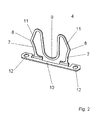
- Fig. 2
- in vergrößerter Darstellung ein Federmittel.
- Gleiche oder gleichwirkende Bauteile sind in der nachfolgenden Beschreibung mit gleichen Bezugszeichen versehen.
- Nachfolgend wird der Aufbau und die Funktionsweise des erfindungsgemäßen elektrischen Installationsgerätes 1 schematisch beschrieben.
- Ein Installationsgerät 1 besteht aus einem nicht dargestellten Gerätesockel und einem Tragrahmen 2, an dem ein Geräteelement 3 mittels eines Federmittels 4 lösbar befestigt werden kann. Das Federmittel 4 ist mittels einer Verschraubung, Verpressung oder Ultraschallschweißen an der Rückseite 5 des Geräteelementes 3 befestigt werden. Des weiteren kann das Federmittel 4 durch Umspritzen bereits bei der Herstellung des Geräteelementes integriert werden. Die Federmittel 4 greifen bei der Montage an dem Tragrahmen 2 federnd in komplementäre Taschen 6 ein.
- Das Federmittel 4 ist als M-fömiger Körper ausgebildet und dessen Schenkel 7 weisen Rastnasen 8 auf, dessen Mittelteil 9 ist bis in die Nähe einer Basis 10 heruntergezogen und dessen Schenkel 7 haben eine gemeinsame Basis 10, wobei die Basis 10 rechtwinklig abgebogen ist. Die beiden Schenkel 7 weisen je eine Anlaufschräge 11 auf. Die Basis 10 weist Befestigungsmittel 12 in Form von Öffnungen auf, die mit Stiften 13 am Geräteelement 3 zusammenwirken und beispielsweise in den Öffnungen verpresst werden. Das Federmittel 4 ist aus einem flächigen Material beispielweise Metallblech ausgestanzt.
-
- 1
- Installationsgerät
- 2
- Tragrahmen
- 3
- Geräteelement
- 4
- Federmittel
- 5
- Rückseite
- 6
- Tasche
- 7
- Schenkel
- 8
- Rastnase
- 9
- Mittelteil
- 10
- Basis
- 11
- Anlaufschräge
- 12
- Befestigungsmittel
- 13
- Stift
Claims (8)
- Elektrisches Installationsgerät umfassend einen Gerätesockel, der mittels eines Tragrahmens (2) in einem Installationsgehäuse befestigbar ist, und ein frontseitig angeordnetes Geräteelement (3), das durch ein Federmittel (4) lösbar an dem Tragrahmen (2) befestigbar ist, dadurch gekennzeichnet, dass das Federmittel (4) als M-fömiger Körper ausgebildet ist und dessen Schenkel (7) Rastnasen (8) aufweisen und dessen Mittelteil (9) bis in die Nähe einer Basis (10) heruntergezogen ist und dessen Schenkel (7) eine gemeinsame Basis (10) haben, wobei die Basis (10) rechtwinklig abgebogen ist, und dass das Federmittel (4) aus einem flächigen Material besteht.
- Elektrisches Installationsgerät nach Patentanspruch 1, dadurch gekennzeichnet, dass das Federmittel (4) aus metallischem Material besteht.
- Elektrisches Installationsgerät nach einem der vorhergehenden Patentansprüche, dadurch gekennzeichnet, dass das Federmittel (4) aus gestanztem Material besteht.
- Elektrisches Installationsgerät nach einem der vorhergehenden Patentansprüche, dadurch gekennzeichnet, dass die beiden Schenkel (7) je eine Anlaufschräge (11) aufweisen.
- Elektrisches Installationsgerät nach einem der vorhergehenden Patentansprüche, dadurch gekennzeichnet, dass das Federmittel (4) an dem Geräteelement (3) angeordnet ist.
- Elektrisches Installationsgerät nach einem der vorhergehenden Patentansprüche, dadurch gekennzeichnet, dass das Federmittel (4) mittels Verpressen oder Ultraschallschweißen an dem Geräteelement (3) befestigbar ist.
- Elektrisches Installationsgerät nach einem der vorhergehenden Patentansprüche, dadurch gekennzeichnet, dass die Basis (10) Befestigungsmittel (12) aufweist.
- Elektrisches Installationsgerät nach einem der vorhergehenden Patentansprüche, dadurch gekennzeichnet, dass das elektrische Installationsgerät (1) als elektrische Steckdose, Schalter, Taster, Bedienteil und/oder Display ausgeführt ist.
Applications Claiming Priority (1)
| Application Number | Priority Date | Filing Date | Title |
|---|---|---|---|
| DE102008063109A DE102008063109A1 (de) | 2008-12-24 | 2008-12-24 | Elektrisches Installationsgerät mit Federmittel |
Publications (3)
| Publication Number | Publication Date |
|---|---|
| EP2202855A2 true EP2202855A2 (de) | 2010-06-30 |
| EP2202855A3 EP2202855A3 (de) | 2013-12-04 |
| EP2202855B1 EP2202855B1 (de) | 2019-07-10 |
Family
ID=42101496
Family Applications (1)
| Application Number | Title | Priority Date | Filing Date |
|---|---|---|---|
| EP09015460.0A Not-in-force EP2202855B1 (de) | 2008-12-24 | 2009-12-15 | Elektrisches Installationsgerät mit Federmittel |
Country Status (3)
| Country | Link |
|---|---|
| EP (1) | EP2202855B1 (de) |
| DE (1) | DE102008063109A1 (de) |
| ES (1) | ES2748283T3 (de) |
Cited By (2)
| Publication number | Priority date | Publication date | Assignee | Title |
|---|---|---|---|---|
| EP3021439A3 (de) * | 2014-11-12 | 2016-08-03 | Abb Ag | Elektronisches installationsgerät |
| EP4216384A1 (de) * | 2022-01-21 | 2023-07-26 | ABB Schweiz AG | Funktionselement für ein gerät der hausinstallationstechnik |
Families Citing this family (3)
| Publication number | Priority date | Publication date | Assignee | Title |
|---|---|---|---|---|
| DE102012106639B3 (de) * | 2012-07-23 | 2013-09-05 | Albrecht Jung Gmbh & Co. Kg | Elektrische/elektronische Installationseinheit |
| DE202016004646U1 (de) | 2016-07-28 | 2016-08-23 | Axel R. Hidde | Elektrisches Installationsgerät |
| DE102021112988B4 (de) | 2021-05-19 | 2024-06-06 | Albrecht Jung Gmbh & Co. Kg | Verrastungsstruktur sowie elektrisches/elektronisches Installationsgerät mit einer solchen Verrastungsstruktur |
Family Cites Families (4)
| Publication number | Priority date | Publication date | Assignee | Title |
|---|---|---|---|---|
| DE1775074B1 (de) * | 1968-07-03 | 1971-05-13 | Merten Geb | Schraubenlose abdeckung fuer elektrische installationsgeraete mit einer abdeckplatte |
| DE20314538U1 (de) * | 2003-09-19 | 2005-01-27 | Merten Gmbh & Co. Kg | Installationsgerät mit Funkantenne |
| CH696899A5 (de) * | 2004-04-05 | 2008-01-15 | Abb Schweiz Ag | Frontplattenbefestigung eines elektrischen Schalters oder Tastensensors. |
| DE102006018800B3 (de) * | 2006-04-22 | 2007-11-22 | Abb Patent Gmbh | Halteelement zur Befestigung eines Abdeckrahmens eines Installationsgerätes |
-
2008
- 2008-12-24 DE DE102008063109A patent/DE102008063109A1/de not_active Ceased
-
2009
- 2009-12-15 EP EP09015460.0A patent/EP2202855B1/de not_active Not-in-force
- 2009-12-15 ES ES09015460T patent/ES2748283T3/es active Active
Non-Patent Citations (1)
| Title |
|---|
| None |
Cited By (2)
| Publication number | Priority date | Publication date | Assignee | Title |
|---|---|---|---|---|
| EP3021439A3 (de) * | 2014-11-12 | 2016-08-03 | Abb Ag | Elektronisches installationsgerät |
| EP4216384A1 (de) * | 2022-01-21 | 2023-07-26 | ABB Schweiz AG | Funktionselement für ein gerät der hausinstallationstechnik |
Also Published As
| Publication number | Publication date |
|---|---|
| EP2202855B1 (de) | 2019-07-10 |
| EP2202855A3 (de) | 2013-12-04 |
| ES2748283T3 (es) | 2020-03-16 |
| DE102008063109A1 (de) | 2010-08-05 |
Similar Documents
| Publication | Publication Date | Title |
|---|---|---|
| DE202005002921U1 (de) | Verbindungssystem, insbesondere elektrisches Verbindungssystem | |
| DE102006045928A1 (de) | Anschlusssystem mit außenliegender Leitungsführung an Wischermotorgehäusen | |
| EP2202855B1 (de) | Elektrisches Installationsgerät mit Federmittel | |
| EP3613110A1 (de) | Baugruppe für ein steckverbinderteil mit einem kontakteinsatz und einem erdungselement | |
| DE102014205744B4 (de) | Steuergerät für ein Fahrzeugheizgerät | |
| EP3021439A2 (de) | Elektronisches installationsgerät | |
| EP0491319B1 (de) | Elektrisches Unterputz-Installationsgerät | |
| DE202008018430U1 (de) | Elektrisches Installationsgerät mit Federmittel | |
| DE102009050595A1 (de) | Elektrische Schutzkontaktsteckdose | |
| EP0649192B1 (de) | Elektrisches Installationsgerät mit Zusatzmodul | |
| EP2124308B1 (de) | Elektrisches Installationsgerät | |
| DE9315918U1 (de) | Elektrisches Installationsgerät mit Zusatzmodul | |
| DE102013109870B3 (de) | Kontaktbaugruppe für elektrische/elektronische Installationsgeräte | |
| EP2315319A1 (de) | Elektrische Schutzkontaktsteckdose | |
| EP2351176B1 (de) | Elektrisches installationsgerät | |
| EP2930809B1 (de) | Elektrisches/elektronisches Installationsgerät | |
| DE1901074B2 (de) | Elektrisches Schaltgerät oder Relais | |
| EP2043118A2 (de) | Elektrisches/elektronisches Installationsgerät | |
| DE102006018800B3 (de) | Halteelement zur Befestigung eines Abdeckrahmens eines Installationsgerätes | |
| DE102024125415B3 (de) | Anordnung umfassend ein Installationsgerät und ein induktives Ladegerät, sowie Verfahren zum induktiven Laden eines Endgerätes | |
| EP2453541A2 (de) | Elektrische Schaltgeräteanordnung | |
| DE10316384A1 (de) | Kontaktadapter für die Kontaktierung einer Antennenstruktur eines Fahrzeuges | |
| DE102017111755B3 (de) | Elektrisches Installationsgerät | |
| DE102011000069B3 (de) | Elektrische Schutzkontaktsteckdose | |
| CH695715A5 (de) | Apparat für elektrische Hausinstallationen. |
Legal Events
| Date | Code | Title | Description |
|---|---|---|---|
| PUAI | Public reference made under article 153(3) epc to a published international application that has entered the european phase |
Free format text: ORIGINAL CODE: 0009012 |
|
| AK | Designated contracting states |
Kind code of ref document: A2 Designated state(s): AT BE BG CH CY CZ DE DK EE ES FI FR GB GR HR HU IE IS IT LI LT LU LV MC MK MT NL NO PL PT RO SE SI SK SM TR |
|
| AX | Request for extension of the european patent |
Extension state: AL BA RS |
|
| PUAL | Search report despatched |
Free format text: ORIGINAL CODE: 0009013 |
|
| AK | Designated contracting states |
Kind code of ref document: A3 Designated state(s): AT BE BG CH CY CZ DE DK EE ES FI FR GB GR HR HU IE IS IT LI LT LU LV MC MK MT NL NO PL PT RO SE SI SK SM TR |
|
| AX | Request for extension of the european patent |
Extension state: AL BA RS |
|
| RIC1 | Information provided on ipc code assigned before grant |
Ipc: H02G 3/12 20060101AFI20131029BHEP Ipc: H02G 3/14 20060101ALI20131029BHEP |
|
| 17P | Request for examination filed |
Effective date: 20140523 |
|
| RBV | Designated contracting states (corrected) |
Designated state(s): AT BE BG CH CY CZ DE DK EE ES FI FR GB GR HR HU IE IS IT LI LT LU LV MC MK MT NL NO PL PT RO SE SI SK SM TR |
|
| 17Q | First examination report despatched |
Effective date: 20140710 |
|
| STAA | Information on the status of an ep patent application or granted ep patent |
Free format text: STATUS: EXAMINATION IS IN PROGRESS |
|
| GRAP | Despatch of communication of intention to grant a patent |
Free format text: ORIGINAL CODE: EPIDOSNIGR1 |
|
| STAA | Information on the status of an ep patent application or granted ep patent |
Free format text: STATUS: GRANT OF PATENT IS INTENDED |
|
| INTG | Intention to grant announced |
Effective date: 20180613 |
|
| RAP1 | Party data changed (applicant data changed or rights of an application transferred) |
Owner name: MERTEN GMBH |
|
| GRAS | Grant fee paid |
Free format text: ORIGINAL CODE: EPIDOSNIGR3 |
|
| GRAA | (expected) grant |
Free format text: ORIGINAL CODE: 0009210 |
|
| STAA | Information on the status of an ep patent application or granted ep patent |
Free format text: STATUS: THE PATENT HAS BEEN GRANTED |
|
| AK | Designated contracting states |
Kind code of ref document: B1 Designated state(s): AT BE BG CH CY CZ DE DK EE ES FI FR GB GR HR HU IE IS IT LI LT LU LV MC MK MT NL NO PL PT RO SE SI SK SM TR |
|
| REG | Reference to a national code |
Ref country code: GB Ref legal event code: FG4D Free format text: NOT ENGLISH |
|
| REG | Reference to a national code |
Ref country code: CH Ref legal event code: EP Ref country code: AT Ref legal event code: REF Ref document number: 1154521 Country of ref document: AT Kind code of ref document: T Effective date: 20190715 |
|
| REG | Reference to a national code |
Ref country code: DE Ref legal event code: R096 Ref document number: 502009015864 Country of ref document: DE |
|
| REG | Reference to a national code |
Ref country code: IE Ref legal event code: FG4D Free format text: LANGUAGE OF EP DOCUMENT: GERMAN |
|
| REG | Reference to a national code |
Ref country code: SE Ref legal event code: TRGR |
|
| REG | Reference to a national code |
Ref country code: NL Ref legal event code: MP Effective date: 20190710 |
|
| REG | Reference to a national code |
Ref country code: LT Ref legal event code: MG4D |
|
| PG25 | Lapsed in a contracting state [announced via postgrant information from national office to epo] |
Ref country code: NO Free format text: LAPSE BECAUSE OF FAILURE TO SUBMIT A TRANSLATION OF THE DESCRIPTION OR TO PAY THE FEE WITHIN THE PRESCRIBED TIME-LIMIT Effective date: 20191010 Ref country code: FI Free format text: LAPSE BECAUSE OF FAILURE TO SUBMIT A TRANSLATION OF THE DESCRIPTION OR TO PAY THE FEE WITHIN THE PRESCRIBED TIME-LIMIT Effective date: 20190710 Ref country code: HR Free format text: LAPSE BECAUSE OF FAILURE TO SUBMIT A TRANSLATION OF THE DESCRIPTION OR TO PAY THE FEE WITHIN THE PRESCRIBED TIME-LIMIT Effective date: 20190710 Ref country code: NL Free format text: LAPSE BECAUSE OF FAILURE TO SUBMIT A TRANSLATION OF THE DESCRIPTION OR TO PAY THE FEE WITHIN THE PRESCRIBED TIME-LIMIT Effective date: 20190710 Ref country code: PT Free format text: LAPSE BECAUSE OF FAILURE TO SUBMIT A TRANSLATION OF THE DESCRIPTION OR TO PAY THE FEE WITHIN THE PRESCRIBED TIME-LIMIT Effective date: 20191111 Ref country code: BG Free format text: LAPSE BECAUSE OF FAILURE TO SUBMIT A TRANSLATION OF THE DESCRIPTION OR TO PAY THE FEE WITHIN THE PRESCRIBED TIME-LIMIT Effective date: 20191010 Ref country code: LT Free format text: LAPSE BECAUSE OF FAILURE TO SUBMIT A TRANSLATION OF THE DESCRIPTION OR TO PAY THE FEE WITHIN THE PRESCRIBED TIME-LIMIT Effective date: 20190710 |
|
| PG25 | Lapsed in a contracting state [announced via postgrant information from national office to epo] |
Ref country code: GR Free format text: LAPSE BECAUSE OF FAILURE TO SUBMIT A TRANSLATION OF THE DESCRIPTION OR TO PAY THE FEE WITHIN THE PRESCRIBED TIME-LIMIT Effective date: 20191011 Ref country code: LV Free format text: LAPSE BECAUSE OF FAILURE TO SUBMIT A TRANSLATION OF THE DESCRIPTION OR TO PAY THE FEE WITHIN THE PRESCRIBED TIME-LIMIT Effective date: 20190710 Ref country code: IS Free format text: LAPSE BECAUSE OF FAILURE TO SUBMIT A TRANSLATION OF THE DESCRIPTION OR TO PAY THE FEE WITHIN THE PRESCRIBED TIME-LIMIT Effective date: 20191110 |
|
| REG | Reference to a national code |
Ref country code: ES Ref legal event code: FG2A Ref document number: 2748283 Country of ref document: ES Kind code of ref document: T3 Effective date: 20200316 |
|
| PG25 | Lapsed in a contracting state [announced via postgrant information from national office to epo] |
Ref country code: TR Free format text: LAPSE BECAUSE OF FAILURE TO SUBMIT A TRANSLATION OF THE DESCRIPTION OR TO PAY THE FEE WITHIN THE PRESCRIBED TIME-LIMIT Effective date: 20190710 |
|
| PG25 | Lapsed in a contracting state [announced via postgrant information from national office to epo] |
Ref country code: RO Free format text: LAPSE BECAUSE OF FAILURE TO SUBMIT A TRANSLATION OF THE DESCRIPTION OR TO PAY THE FEE WITHIN THE PRESCRIBED TIME-LIMIT Effective date: 20190710 Ref country code: PL Free format text: LAPSE BECAUSE OF FAILURE TO SUBMIT A TRANSLATION OF THE DESCRIPTION OR TO PAY THE FEE WITHIN THE PRESCRIBED TIME-LIMIT Effective date: 20190710 Ref country code: DK Free format text: LAPSE BECAUSE OF FAILURE TO SUBMIT A TRANSLATION OF THE DESCRIPTION OR TO PAY THE FEE WITHIN THE PRESCRIBED TIME-LIMIT Effective date: 20190710 Ref country code: IT Free format text: LAPSE BECAUSE OF FAILURE TO SUBMIT A TRANSLATION OF THE DESCRIPTION OR TO PAY THE FEE WITHIN THE PRESCRIBED TIME-LIMIT Effective date: 20190710 Ref country code: EE Free format text: LAPSE BECAUSE OF FAILURE TO SUBMIT A TRANSLATION OF THE DESCRIPTION OR TO PAY THE FEE WITHIN THE PRESCRIBED TIME-LIMIT Effective date: 20190710 |
|
| PG25 | Lapsed in a contracting state [announced via postgrant information from national office to epo] |
Ref country code: CZ Free format text: LAPSE BECAUSE OF FAILURE TO SUBMIT A TRANSLATION OF THE DESCRIPTION OR TO PAY THE FEE WITHIN THE PRESCRIBED TIME-LIMIT Effective date: 20190710 Ref country code: SM Free format text: LAPSE BECAUSE OF FAILURE TO SUBMIT A TRANSLATION OF THE DESCRIPTION OR TO PAY THE FEE WITHIN THE PRESCRIBED TIME-LIMIT Effective date: 20190710 Ref country code: IS Free format text: LAPSE BECAUSE OF FAILURE TO SUBMIT A TRANSLATION OF THE DESCRIPTION OR TO PAY THE FEE WITHIN THE PRESCRIBED TIME-LIMIT Effective date: 20200224 Ref country code: SK Free format text: LAPSE BECAUSE OF FAILURE TO SUBMIT A TRANSLATION OF THE DESCRIPTION OR TO PAY THE FEE WITHIN THE PRESCRIBED TIME-LIMIT Effective date: 20190710 |
|
| REG | Reference to a national code |
Ref country code: DE Ref legal event code: R097 Ref document number: 502009015864 Country of ref document: DE |
|
| PLBE | No opposition filed within time limit |
Free format text: ORIGINAL CODE: 0009261 |
|
| STAA | Information on the status of an ep patent application or granted ep patent |
Free format text: STATUS: NO OPPOSITION FILED WITHIN TIME LIMIT |
|
| PG2D | Information on lapse in contracting state deleted |
Ref country code: IS |
|
| REG | Reference to a national code |
Ref country code: CH Ref legal event code: PL |
|
| 26N | No opposition filed |
Effective date: 20200603 |
|
| REG | Reference to a national code |
Ref country code: BE Ref legal event code: MM Effective date: 20191231 |
|
| PG25 | Lapsed in a contracting state [announced via postgrant information from national office to epo] |
Ref country code: SI Free format text: LAPSE BECAUSE OF FAILURE TO SUBMIT A TRANSLATION OF THE DESCRIPTION OR TO PAY THE FEE WITHIN THE PRESCRIBED TIME-LIMIT Effective date: 20190710 Ref country code: MC Free format text: LAPSE BECAUSE OF FAILURE TO SUBMIT A TRANSLATION OF THE DESCRIPTION OR TO PAY THE FEE WITHIN THE PRESCRIBED TIME-LIMIT Effective date: 20190710 |
|
| GBPC | Gb: european patent ceased through non-payment of renewal fee |
Effective date: 20191215 |
|
| PG25 | Lapsed in a contracting state [announced via postgrant information from national office to epo] |
Ref country code: GB Free format text: LAPSE BECAUSE OF NON-PAYMENT OF DUE FEES Effective date: 20191215 Ref country code: LU Free format text: LAPSE BECAUSE OF NON-PAYMENT OF DUE FEES Effective date: 20191215 Ref country code: IE Free format text: LAPSE BECAUSE OF NON-PAYMENT OF DUE FEES Effective date: 20191215 |
|
| PG25 | Lapsed in a contracting state [announced via postgrant information from national office to epo] |
Ref country code: BE Free format text: LAPSE BECAUSE OF NON-PAYMENT OF DUE FEES Effective date: 20191231 Ref country code: LI Free format text: LAPSE BECAUSE OF NON-PAYMENT OF DUE FEES Effective date: 20191231 Ref country code: CH Free format text: LAPSE BECAUSE OF NON-PAYMENT OF DUE FEES Effective date: 20191231 |
|
| REG | Reference to a national code |
Ref country code: AT Ref legal event code: MM01 Ref document number: 1154521 Country of ref document: AT Kind code of ref document: T Effective date: 20191215 |
|
| PG25 | Lapsed in a contracting state [announced via postgrant information from national office to epo] |
Ref country code: AT Free format text: LAPSE BECAUSE OF NON-PAYMENT OF DUE FEES Effective date: 20191215 Ref country code: CY Free format text: LAPSE BECAUSE OF FAILURE TO SUBMIT A TRANSLATION OF THE DESCRIPTION OR TO PAY THE FEE WITHIN THE PRESCRIBED TIME-LIMIT Effective date: 20190710 |
|
| PG25 | Lapsed in a contracting state [announced via postgrant information from national office to epo] |
Ref country code: HU Free format text: LAPSE BECAUSE OF FAILURE TO SUBMIT A TRANSLATION OF THE DESCRIPTION OR TO PAY THE FEE WITHIN THE PRESCRIBED TIME-LIMIT; INVALID AB INITIO Effective date: 20091215 Ref country code: MT Free format text: LAPSE BECAUSE OF FAILURE TO SUBMIT A TRANSLATION OF THE DESCRIPTION OR TO PAY THE FEE WITHIN THE PRESCRIBED TIME-LIMIT Effective date: 20190710 |
|
| PG25 | Lapsed in a contracting state [announced via postgrant information from national office to epo] |
Ref country code: MK Free format text: LAPSE BECAUSE OF FAILURE TO SUBMIT A TRANSLATION OF THE DESCRIPTION OR TO PAY THE FEE WITHIN THE PRESCRIBED TIME-LIMIT Effective date: 20190710 |
|
| PGFP | Annual fee paid to national office [announced via postgrant information from national office to epo] |
Ref country code: SE Payment date: 20231110 Year of fee payment: 15 Ref country code: FR Payment date: 20231108 Year of fee payment: 15 Ref country code: DE Payment date: 20231031 Year of fee payment: 15 |
|
| PGFP | Annual fee paid to national office [announced via postgrant information from national office to epo] |
Ref country code: ES Payment date: 20240116 Year of fee payment: 15 |
|
| REG | Reference to a national code |
Ref country code: DE Ref legal event code: R119 Ref document number: 502009015864 Country of ref document: DE |
|
| REG | Reference to a national code |
Ref country code: SE Ref legal event code: EUG |
|
| PG25 | Lapsed in a contracting state [announced via postgrant information from national office to epo] |
Ref country code: DE Free format text: LAPSE BECAUSE OF NON-PAYMENT OF DUE FEES Effective date: 20250701 |
|
| PG25 | Lapsed in a contracting state [announced via postgrant information from national office to epo] |
Ref country code: FR Free format text: LAPSE BECAUSE OF NON-PAYMENT OF DUE FEES Effective date: 20241231 |
|
| REG | Reference to a national code |
Ref country code: ES Ref legal event code: FD2A Effective date: 20260129 |
|
| PG25 | Lapsed in a contracting state [announced via postgrant information from national office to epo] |
Ref country code: ES Free format text: LAPSE BECAUSE OF NON-PAYMENT OF DUE FEES Effective date: 20241216 |