EP2203205B1 - Inhalateur - Google Patents
Inhalateur Download PDFInfo
- Publication number
- EP2203205B1 EP2203205B1 EP20080803342 EP08803342A EP2203205B1 EP 2203205 B1 EP2203205 B1 EP 2203205B1 EP 20080803342 EP20080803342 EP 20080803342 EP 08803342 A EP08803342 A EP 08803342A EP 2203205 B1 EP2203205 B1 EP 2203205B1
- Authority
- EP
- European Patent Office
- Prior art keywords
- housing
- cartridge
- hand
- held device
- indexing mechanism
- Prior art date
- Legal status (The legal status is an assumption and is not a legal conclusion. Google has not performed a legal analysis and makes no representation as to the accuracy of the status listed.)
- Active
Links
Images



Classifications
-
- A—HUMAN NECESSITIES
- A61—MEDICAL OR VETERINARY SCIENCE; HYGIENE
- A61M—DEVICES FOR INTRODUCING MEDIA INTO, OR ONTO, THE BODY; DEVICES FOR TRANSDUCING BODY MEDIA OR FOR TAKING MEDIA FROM THE BODY; DEVICES FOR PRODUCING OR ENDING SLEEP OR STUPOR
- A61M15/00—Inhalators
- A61M15/009—Inhalators using medicine packages with incorporated spraying means, e.g. aerosol cans
-
- A—HUMAN NECESSITIES
- A61—MEDICAL OR VETERINARY SCIENCE; HYGIENE
- A61M—DEVICES FOR INTRODUCING MEDIA INTO, OR ONTO, THE BODY; DEVICES FOR TRANSDUCING BODY MEDIA OR FOR TAKING MEDIA FROM THE BODY; DEVICES FOR PRODUCING OR ENDING SLEEP OR STUPOR
- A61M15/00—Inhalators
- A61M15/0065—Inhalators with dosage or measuring devices
- A61M15/0068—Indicating or counting the number of dispensed doses or of remaining doses
- A61M15/007—Mechanical counters
- A61M15/0071—Mechanical counters having a display or indicator
- A61M15/0073—Mechanical counters having a display or indicator on a ring
-
- G—PHYSICS
- G06—COMPUTING OR CALCULATING; COUNTING
- G06M—COUNTING MECHANISMS; COUNTING OF OBJECTS NOT OTHERWISE PROVIDED FOR
- G06M1/00—Design features of general application
- G06M1/04—Design features of general application for driving the stage of lowest order
-
- G—PHYSICS
- G06—COMPUTING OR CALCULATING; COUNTING
- G06M—COUNTING MECHANISMS; COUNTING OF OBJECTS NOT OTHERWISE PROVIDED FOR
- G06M1/00—Design features of general application
- G06M1/08—Design features of general application for actuating the drive
- G06M1/083—Design features of general application for actuating the drive by mechanical means
Definitions
- the invention relates to a hand-held device for portioned dispensing of sprayable substances, in particular inhalants, according to the preamble of the main claim.
- Handpieces of the type in question are already known ( WO 2006/051073 ). They find particular application in medical aerosol therapy for the treatment of respiratory diseases.
- the held in the housing, pressurized cartridge contains the drug to be inhaled, with the release or the same ejection of an axial displacement of the cartridge is required in the housing.
- the known solutions are complex and user-friendly, especially in view of the internal tolerances of the stepper mechanism and the often restless hand of some patients.
- the object of the invention is therefore to design a handset of the type in question in a favorable manner with a simplified structure so that especially the switching steps can be performed easily and safely.
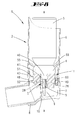
- Hand-held device 1 shown in a schematic sectional view serves for the portioned dispensing of sprayable substances, in particular of inhalation medicaments.
- the handset 1 first on a handset housing 2, in which a sprayable substance-containing cartridge 3 is used.
- This cartridge 3 is axially displaceable in the housing 2.
- the cartridge head 4 has a central, coaxial with the cartridge 3 extending valve tube 5. About the latter, a drug output is achieved by an axial relative movement between the cartridge 3 and housing 2.
- the housing 2 is divided into two and consists essentially of two superimposed ring parts 6 and 7, of which the upper ring part 6 is formed like a shaft and the lower ring part 7 has an approximately transversely to the extension Schöffershalst mouthpiece 8. The latter can be closed by a cap, not shown.
- valve tube 5 of the cartridge 3 is supported in an associated tubular support portion 9 within the lower ring member 7, this with axial mobility of the cartridge 3 within the surrounding the cartridge 3, shaft-like ring member. 6
- valve tube 5 of the cartridge 3 clamping receiving, formed within the lower housing ring member 7 support portion 9 is provided with a relation to a valve tube end receiving portion diameter-reduced flow channel 10, which fluidly in connection is with the valve tube 5, wherein the valve tube 5 facing away from the end of the flow channel 10 in the direction of the mouthpiece 8 has.
- the two ring parts 6 and 7 are pluggable connected in the illustrated embodiment.
- the two parts can also be connected to one another via a thread, for example via a coarse thread with a high pitch.
- the arrangement of the cartridge 3 in the housing 2 is chosen so that the cartridge head 4 is placed in the housing 2 approximately at the height of the connecting portion between the ring member 6 and ring member 7.
- a stepping mechanism 11 is arranged in overlap with the cartridge valve tube 5. This is used to register and display the executed output actuation, this in dependence on the performed opening strokes of the cartridge.
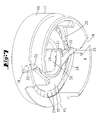
- the stepping mechanism 11 is in Fig. 1 shown in a perspective exploded view.
- the central component of the stepping mechanism 11 is a planetary gear 12, consisting of a planetary gear 13, a sun gear 14, which sits on a underside toothed disc 15 and a cooperating with the planet gear 13 ring gear 16.
- the latter is the inside of a non-rotatably salaried, pipe section-shaped ring 17 formed.
- the jacket wall 18 of the ring 17 is penetrated in diametrically opposite areas of obliquely upward directed in the direction of switching outgoing slots 19, which open down to the ring gear 16 facing away from the ring edge open.
- the sprocket 16 extends in the axial direction approximately over half the height of the ring 17, whose shell wall 18 stepped to the ring gear 16 facing away from the annular end edge, is formed radially tapering.
- a latching finger 20 is integrally formed on the inside of the jacket wall 18 of the ring 17. This is offset with respect to a floor plan of the ring relative to the ring gear 16 radially inward; engages accordingly in a circular space drawn into the ring gear 16 radially inward.
- the arrangement of approximately elastically formed in the vertical direction locking finger 20 is chosen so that it engages from below into the teeth 21.
- the diameter of the sun gear 14-carrying disc 15 is selected to be slightly smaller than the inner diameter of the ring 17 in the region of the ring gear 16.
- sun gear 14 and disc 15 are preferably integrally formed of the same material.
- the underside of the disc 15 provided teeth 21 are peripheral edge circumferentially and provided as a serration 21.
- the sun gear 14 has a rough toothing.
- eight sun gear teeth 22 are formed evenly distributed. These teeth 22 cooperate in the course of the sun gear rotation with the arranged in the same plane between the sun gear 14 and the ring gear 16 of the ring 17 planetary gear 13.
- the planet gear 13 has a unilaterally upwards, ie away from the disc 15 of the sun gear 14 away axle journal 23. This is rotatably taken in a bore 24 in the region of a disk-like radially inwardly facing collar 25 of a scale ring 26.
- the scale ring 26 is mantelau connectedwandig with a circumferential scale graduation 27 provided, wherein the graduated scale corresponds to a plurality of individual rotary steps of the scale ring 26 continuing planetary gear 13.
- the indexing fingers 28 are arranged diametrically opposite to the main axis x of the entire stepper mechanism 11.
- a cylindrical central body in the form of a hub 29 is provided with a central axial through-hole 30.
- Their diameter is dimensioned slightly larger than the outer diameter of this through-hole 30 to be penetrated cartridge valve tube fifth
- the hub 29 merges into a radially enlarged collar 31.
- projecting guide portions 32 are formed, each forming in the region of their free ends in the associated slot 19 of the ring 17 guide pins 33.
- the indexing fingers 28 are each rooted with a horizontal portion on the guide portions 32 leaving the guide portion 33 projecting radially outward from the horizontal portion.
- the indexing fingers 28 projecting from the horizontal portions extend obliquely upward, such as at an angle of 45 degrees to the horizontal to the skewing of the slots 19 in the ring 17.
- the stepping finger star thus formed carries the reference S.
- the stepping finger star S, the inner ring gear 16 having ring 17, the integrally formed with the sun gear 14 disc 15 and the scale ring 26 are aligned concentrically with each other on the axis x, wherein the height of the ring 17 is selected so that both the Stepping finger star S and the sun gear 14 together with disc 15 are included in this.
- the slots 19 are composed of two sections, one of which is directed obliquely to the longitudinal axis xx and enforces the rotation of the indexing fingers and the second, adjoining section, is directed parallel to the longitudinal axis xx.
- the latter widens slightly towards the upper end, so that the guide pins 33 enter there with play (see FIG. 7 ), in particular against the direction of rotation, which forces the first inclined portion of the slot 19.
- the stroke which allows the stepping finger star in the rectilinear upward slot portion brings a further tension of the inner spring ring of the indexing finger 28 - without any rotation of the same - whereby the force - after releasing the cartridge - for resetting the stepper to the starting position significantly is increased.
- the entire planetary gear 12, as well as the stepping finger star S and the scale ring 26 are accommodated in a pot-like stepper housing 34 with an outer diameter, which is adapted to the outer diameter of the cartridge 3.
- the housing 34 has a jacket wall 35. This has a viewing window 36 through which the scale graduation 27 of the scale ring 26 can be seen.
- the housing cover 37 has a central opening 38, which in the in FIG. 1 embodiment shown is conical from the housing interior tapered locking spring tongues in the in FIG. 1
- the opening diameter is adapted to a diameter of a waist portion 40 of a centrally projecting beyond the opening-side end wall of the cartridge 3 collar 41, from which latter the valve tube 5 grows.
- the housing bottom 42 is formed by a separate part. This is connected to the housing 34 receiving the above-described stepper mechanism parts, so for example. Welded with this or held by a press fit on this.
- the plate-like housing bottom 42 has a central bore for the passage of the valve tube 5. Furthermore, a locking piece 44 is formed on the housing bottom 42, which engages the position-oriented bondage of the ring 17 in a correspondingly formed in the jacket wall 18, window-like recess 45.
- the jacket outer wall of the housing bottom 42 has a cutout 46. In the installed state, this is assigned to the region of the outlet cross section of the flow channel 10 in the lower ring part housing 7.
- the stepping mechanism 11 is arranged corresponding concentric to the valve tube 5 in the shadow of the cartridge 3 within the housing 2, this concretely in the space between the cartridge head 4 and support portion 9 of the housing 2 space.
- the stepping mechanism 11 is supported on the end face of the support section 9 of the inhalation housing 2 with the hub 29 of the indexing finger star S mounted centrally in the rear derailleur housing 34.
- the central axis x of the cutting mechanism 11 is taken over by the body axis of the cartridge 3.
- the hub 29 passing through the valve tube 5 provides additional centering of the entire stepper unit.
- the associated portions of the housing ring parts 6 and 7 also viewing window 47, 48, which are through the selected position, facing the mouthpiece 8 of the housing 2, in the field of view of the handset 1 serving user.
- this is provided with a projecting radially from the housing 34 guide blade 49 which engages in a vertical groove not shown in the interior of the housing 2, permitting the displacement during lifting operation.
- stepper mechanism 11 may also be a latching between the stepper mechanism 11 and cartridge 3 in the region of the cartridge head side collar 41 to be selected so that upon removal of the cartridge 3 from the housing 2, the stepper mechanism 11 is pulled on the cartridge 3 with remaining. But it can as well, as in FIG. 9 shown, the cartridge and the pacer be removed separately, especially because the stepper is self-sufficient in terms of springback.
Landscapes
- Engineering & Computer Science (AREA)
- Health & Medical Sciences (AREA)
- Life Sciences & Earth Sciences (AREA)
- Animal Behavior & Ethology (AREA)
- Public Health (AREA)
- Pulmonology (AREA)
- Anesthesiology (AREA)
- Biomedical Technology (AREA)
- Heart & Thoracic Surgery (AREA)
- Hematology (AREA)
- Theoretical Computer Science (AREA)
- General Health & Medical Sciences (AREA)
- Bioinformatics & Cheminformatics (AREA)
- Veterinary Medicine (AREA)
- Physics & Mathematics (AREA)
- General Physics & Mathematics (AREA)
- Biophysics (AREA)
- Containers And Packaging Bodies Having A Special Means To Remove Contents (AREA)
- Infusion, Injection, And Reservoir Apparatuses (AREA)
- Nozzles (AREA)
Claims (6)
- Appareil à main (1) pour la distribution par portion de substances pulvérisables, en particulier des médicaments à inhaler, comportant une cartouche (3) pouvant être déplacée par pression sur un boîtier dans la position de distribution, et un mécanisme pas à pas (11) déplacé en même temps lors de la course d'ouverture de la cartouche (3) par celle-ci pour enregistrer et afficher des actionnements de distribution réalisés, lequel mécanisme pas à pas (11) présente une bague graduée (26) tournant de façon concentrique par rapport au tube à soupape (5) devant une fenêtre de visualisation (36, 47, 48) et un disque denté (15) côté inférieur, dans lequel, lors d'un déplacement axial du boîtier de mécanisme pas à pas (34), des doigts de fonction pas à pas (28) viennent en prise, par lesquels, à partir de tenons de guidage (33) mobiles dans des fentes obliques (19), un mouvement de rotation est imposé, caractérisé en ce que le parcours oblique des fentes (19) ne s'étend que sur une partie de la hauteur de course du boîtier du mécanisme pas à pas (34) et les tenons de guidage (33) se décalent par la course résiduelle du mécanisme pas à pas (11) parallèlement à l'axe longitudinal du mécanisme pas à pas (x-x).
- Appareil à main selon la revendication 1, caractérisé en ce que les tenons de guidage sont conduits par la course résiduelle dans les fentes avec du jeu.
- Appareil à main selon la revendication 1, caractérisé par un doigt d'arrêt (20) qui est en prise dans la zone entre les deux doigts de fonction pas à pas (28) dans la même denture (21) que les doigts de fonction pas à pas (28).
- Appareil à main selon la revendication 1, caractérisé en ce qu'une tension de ressort opposée à la course d'ouverture est intrinsèque aux doigts de fonction pas à pas.
- Appareil à main selon la revendication 1, caractérisé en ce que le boîtier de mécanisme pas à pas est conduit de façon linéaire dans le boîtier d'inhalation.
- Appareil à main selon la revendication 5, caractérisé en ce que le guidage est obtenu par une feuille de guidage (49) dans une rainure verticale (52).
Priority Applications (1)
| Application Number | Priority Date | Filing Date | Title |
|---|---|---|---|
| PL08803342T PL2203205T3 (pl) | 2007-09-22 | 2008-08-28 | Inhalator |
Applications Claiming Priority (2)
| Application Number | Priority Date | Filing Date | Title |
|---|---|---|---|
| DE102007045438.6A DE102007045438B4 (de) | 2007-09-22 | 2007-09-22 | Inhalier-Gerät |
| PCT/EP2008/061337 WO2009037085A1 (fr) | 2007-09-22 | 2008-08-28 | Inhalateur |
Publications (2)
| Publication Number | Publication Date |
|---|---|
| EP2203205A1 EP2203205A1 (fr) | 2010-07-07 |
| EP2203205B1 true EP2203205B1 (fr) | 2015-05-06 |
Family
ID=40083622
Family Applications (1)
| Application Number | Title | Priority Date | Filing Date |
|---|---|---|---|
| EP20080803342 Active EP2203205B1 (fr) | 2007-09-22 | 2008-08-28 | Inhalateur |
Country Status (10)
| Country | Link |
|---|---|
| US (1) | US8474447B2 (fr) |
| EP (1) | EP2203205B1 (fr) |
| JP (1) | JP5436430B2 (fr) |
| CA (1) | CA2700201C (fr) |
| DE (1) | DE102007045438B4 (fr) |
| DK (1) | DK2203205T3 (fr) |
| ES (1) | ES2539285T3 (fr) |
| HU (1) | HUE025069T2 (fr) |
| PL (1) | PL2203205T3 (fr) |
| WO (1) | WO2009037085A1 (fr) |
Families Citing this family (20)
| Publication number | Priority date | Publication date | Assignee | Title |
|---|---|---|---|---|
| GB0920499D0 (en) * | 2009-11-23 | 2010-01-06 | 3M Innovative Properties Co | Dose counter |
| GB0921555D0 (en) | 2009-12-09 | 2010-01-27 | 3M Innovative Properties Co | Dose indicator |
| GB201118842D0 (en) * | 2011-11-01 | 2011-12-14 | Euro Celtique Sa | Dispenser cap arrangement |
| DE102013212325A1 (de) * | 2013-06-26 | 2014-12-31 | B. Braun Melsungen Ag | Einstellvorrichtung für einen Durchflussregler |
| DE102014114462A1 (de) * | 2013-10-15 | 2015-04-16 | Alfred Von Schuckmann | Zählwerk und Handgerät mit Zählwerk |
| AU2015257878B2 (en) | 2014-05-07 | 2019-08-08 | Boehringer Ingelheim International Gmbh | Container, nebulizer and use |
| BR112016023719B1 (pt) | 2014-05-07 | 2021-12-21 | Boehringer Ingelheim International Gmbh | Nebulizador para um fluido e recipiente para um nebulizador |
| HUE055604T2 (hu) | 2014-05-07 | 2021-12-28 | Boehringer Ingelheim Int | Porlasztó |
| KR102409529B1 (ko) | 2014-05-07 | 2022-06-17 | 베링거 인겔하임 인터내셔날 게엠베하 | 컨테이너, 표시 디바이스 및 분무기 |
| MX379196B (es) | 2014-05-07 | 2025-03-10 | Boehringer Ingelheim Int | Nebulizador. |
| EA035261B1 (ru) | 2014-05-07 | 2020-05-21 | Бёрингер Ингельхайм Интернациональ Гмбх | Небулайзер и контейнер |
| US20170182268A1 (en) * | 2014-05-28 | 2017-06-29 | Sanofi Sa | Assembly for a counter mechanism for a drug delivery device and drug delivery device |
| CA2962947C (fr) * | 2014-09-29 | 2021-02-23 | Dermira, Inc. | Dispositif et procede de distribution de medicament |
| CN104971413B (zh) * | 2015-06-30 | 2023-04-14 | 上海臣邦医药科技股份有限公司 | 一种粉雾剂给药装置的防误操作单元及防误操作方法 |
| EP3370810B1 (fr) | 2015-11-06 | 2019-12-18 | Boehringer Ingelheim International GmbH | Système avec nébuliseur et récipient |
| DE102016106875A1 (de) * | 2016-04-13 | 2017-10-19 | Alfred Von Schuckmann | Handgerät zur Ausgabe einer pharmazeutischen Substanz sowie Zählwerk für ein solches Handgerät |
| CN107041986A (zh) * | 2017-04-17 | 2017-08-15 | 苏州新劢德医疗器械科技有限公司 | 粉末药品吸入器 |
| DE102018117106A1 (de) | 2018-07-16 | 2020-01-16 | Alfred Von Schuckmann | Handgerät zur portionierten Ausgabe sprühfähiger Substanzen |
| CN110559528B (zh) * | 2019-10-12 | 2024-06-07 | 万通(苏州)定量阀系统有限公司 | 一种带计数器的气雾剂给药器推钮 |
| WO2025016875A1 (fr) | 2023-07-20 | 2025-01-23 | Alfred Von Schuckmann | Dispositif portatif pour distribution d'une substance pharmaceutique en portions |
Family Cites Families (10)
| Publication number | Priority date | Publication date | Assignee | Title |
|---|---|---|---|---|
| TW533865U (en) * | 1997-06-10 | 2003-05-21 | Glaxo Group Ltd | Dispenser for dispensing medicament and actuation indicating device |
| DE19963946C2 (de) * | 1999-08-27 | 2001-07-26 | Schuckmann Alfred Von | Handbetätigter Inhalator für pulverförmige Substanzen |
| GB2385640B (en) * | 2001-02-23 | 2003-10-15 | Bespak Plc | Dosage counting devices |
| GB2372543B (en) * | 2001-02-23 | 2003-08-20 | Bespak Plc | Dosage counting devices |
| EP1369139A1 (fr) * | 2002-06-03 | 2003-12-10 | 3M Innovative Properties Company | Indicateurs de dose et systèmes de dispension comprenants des nourrisses et des indicateurs |
| AU2002325239A1 (en) | 2002-06-12 | 2003-12-31 | Steag Mikcroparts Gmbh | Counter for counting metered doses of liquid, pasty, or solid products and device for the metered dispensing of such products |
| AU2002953483A0 (en) * | 2002-12-20 | 2003-01-09 | Acrux Dds Pty. Ltd. | Usage indicator |
| FR2858867B1 (fr) | 2003-08-12 | 2005-11-04 | Valois Sa | Indicateur de doses pour dispositif de distribution de produit fluide |
| DE202005021637U1 (de) * | 2004-09-04 | 2009-01-22 | Schuckmann, Alfred Von | Inhalier-Gerät |
| DE102005033398A1 (de) | 2004-11-10 | 2006-05-11 | Alfred Von Schuckmann | Inhalier-Gerät |
-
2007
- 2007-09-22 DE DE102007045438.6A patent/DE102007045438B4/de active Active
-
2008
- 2008-08-28 DK DK08803342.8T patent/DK2203205T3/en active
- 2008-08-28 US US12/677,555 patent/US8474447B2/en active Active
- 2008-08-28 HU HUE08803342A patent/HUE025069T2/en unknown
- 2008-08-28 PL PL08803342T patent/PL2203205T3/pl unknown
- 2008-08-28 EP EP20080803342 patent/EP2203205B1/fr active Active
- 2008-08-28 WO PCT/EP2008/061337 patent/WO2009037085A1/fr not_active Ceased
- 2008-08-28 ES ES08803342.8T patent/ES2539285T3/es active Active
- 2008-08-28 JP JP2010525295A patent/JP5436430B2/ja active Active
- 2008-08-28 CA CA2700201A patent/CA2700201C/fr active Active
Also Published As
| Publication number | Publication date |
|---|---|
| JP2010538780A (ja) | 2010-12-16 |
| WO2009037085A1 (fr) | 2009-03-26 |
| HUE025069T2 (en) | 2016-01-28 |
| JP5436430B2 (ja) | 2014-03-05 |
| CA2700201C (fr) | 2015-12-15 |
| PL2203205T3 (pl) | 2015-10-30 |
| US8474447B2 (en) | 2013-07-02 |
| DE102007045438A1 (de) | 2009-04-02 |
| DK2203205T3 (en) | 2015-08-10 |
| DE102007045438B4 (de) | 2016-09-01 |
| ES2539285T3 (es) | 2015-06-29 |
| CA2700201A1 (fr) | 2009-03-26 |
| US20100229857A1 (en) | 2010-09-16 |
| EP2203205A1 (fr) | 2010-07-07 |
Similar Documents
| Publication | Publication Date | Title |
|---|---|---|
| EP2203205B1 (fr) | Inhalateur | |
| EP1868141B1 (fr) | Inhalateur | |
| DE60209214T2 (de) | Dosierzähleinrichtung | |
| DE60115480T2 (de) | Inhalationsgerät | |
| EP0831947A1 (fr) | Dispositif d'injection | |
| DE60020189T2 (de) | Spender zur Abgabe abgemessener Mengen einer Flüssigkeit, versehen mit einer Vorrichtung zum Zählen einer großen Zahl abgegebener Dosen | |
| DE69502103T2 (de) | Dosenzähler für inhalatoren | |
| DE60209211T2 (de) | Dosierzähleinrichtung | |
| WO1997036626A1 (fr) | Dispositif d'injection | |
| EP0581788A1 (fr) | Dispositif d'injection. | |
| EP3102257B1 (fr) | Dispositif d'injection | |
| EP2851131B1 (fr) | Dispositif de dépôt pour fluide provenant d'un récipient de fluide | |
| EP2318079B1 (fr) | Unité d'entraînement pour un compteur de dose | |
| DE102006029753A1 (de) | Inhalator für pulverförmige Substanzen | |
| EP3058516B1 (fr) | Compteur et appareil portatif équipé d'un compteur | |
| EP2659978B1 (fr) | Pipette avec systeme de blockage | |
| DE3129286A1 (de) | Zahnaerztliches handstueck | |
| EP0848623A1 (fr) | Dispositif d'injection de liquide | |
| WO2017178294A1 (fr) | Appareil à main destiné à distribuer une substance pharmaceutique ainsi que compteur pour un tel appareil à main | |
| DE60301484T2 (de) | Ampulle für einen Flüssigkeitszerstäuber | |
| DE102008030443A1 (de) | Schrittschaltwerk sowie Handgerät zur portionierten Ausgabe sprühfähiger Substanzen | |
| DE102006049614A1 (de) | Inhalier-Gerät | |
| DE102006040194A1 (de) | Handgerät zur portionierten Ausgabe sprühfähiger Substanzen | |
| DE102020211145A1 (de) | Vorrichtung und Verfahren zum vereinzelnden Dosieren von Festkörperportionen | |
| DE20013636U1 (de) | Flüssigkeitsspender |
Legal Events
| Date | Code | Title | Description |
|---|---|---|---|
| PUAI | Public reference made under article 153(3) epc to a published international application that has entered the european phase |
Free format text: ORIGINAL CODE: 0009012 |
|
| 17P | Request for examination filed |
Effective date: 20100422 |
|
| AK | Designated contracting states |
Kind code of ref document: A1 Designated state(s): AT BE BG CH CY CZ DE DK EE ES FI FR GB GR HR HU IE IS IT LI LT LU LV MC MT NL NO PL PT RO SE SI SK TR |
|
| AX | Request for extension of the european patent |
Extension state: AL BA MK RS |
|
| DAX | Request for extension of the european patent (deleted) | ||
| RIN1 | Information on inventor provided before grant (corrected) |
Inventor name: HOELZL, HUBERT Inventor name: HOCHRAINER, DIETER Inventor name: VON SCHUCKMANN, ALFRED |
|
| REG | Reference to a national code |
Ref country code: DE Ref legal event code: R079 Ref document number: 502008012970 Country of ref document: DE Free format text: PREVIOUS MAIN CLASS: A61M0015000000 Ipc: G06M0001040000 |
|
| GRAP | Despatch of communication of intention to grant a patent |
Free format text: ORIGINAL CODE: EPIDOSNIGR1 |
|
| RIC1 | Information provided on ipc code assigned before grant |
Ipc: A61M 15/00 20060101ALI20141212BHEP Ipc: G06M 1/08 20060101ALI20141212BHEP Ipc: G06M 1/04 20060101AFI20141212BHEP |
|
| RIN1 | Information on inventor provided before grant (corrected) |
Inventor name: VON SCHUCKMANN, ALFRED Inventor name: HOCHRAINER, DIETER Inventor name: HOELZL, HUBERT |
|
| INTG | Intention to grant announced |
Effective date: 20150119 |
|
| GRAS | Grant fee paid |
Free format text: ORIGINAL CODE: EPIDOSNIGR3 |
|
| GRAA | (expected) grant |
Free format text: ORIGINAL CODE: 0009210 |
|
| AK | Designated contracting states |
Kind code of ref document: B1 Designated state(s): AT BE BG CH CY CZ DE DK EE ES FI FR GB GR HR HU IE IS IT LI LT LU LV MC MT NL NO PL PT RO SE SI SK TR |
|
| REG | Reference to a national code |
Ref country code: GB Ref legal event code: FG4D Free format text: NOT ENGLISH |
|
| REG | Reference to a national code |
Ref country code: CH Ref legal event code: EP |
|
| REG | Reference to a national code |
Ref country code: IE Ref legal event code: FG4D Free format text: LANGUAGE OF EP DOCUMENT: GERMAN |
|
| REG | Reference to a national code |
Ref country code: AT Ref legal event code: REF Ref document number: 726162 Country of ref document: AT Kind code of ref document: T Effective date: 20150615 |
|
| REG | Reference to a national code |
Ref country code: DE Ref legal event code: R096 Ref document number: 502008012970 Country of ref document: DE Effective date: 20150618 |
|
| REG | Reference to a national code |
Ref country code: ES Ref legal event code: FG2A Ref document number: 2539285 Country of ref document: ES Kind code of ref document: T3 Effective date: 20150629 |
|
| REG | Reference to a national code |
Ref country code: NL Ref legal event code: T3 |
|
| REG | Reference to a national code |
Ref country code: DK Ref legal event code: T3 Effective date: 20150805 |
|
| REG | Reference to a national code |
Ref country code: SE Ref legal event code: TRGR |
|
| REG | Reference to a national code |
Ref country code: LT Ref legal event code: MG4D |
|
| PG25 | Lapsed in a contracting state [announced via postgrant information from national office to epo] |
Ref country code: FI Free format text: LAPSE BECAUSE OF FAILURE TO SUBMIT A TRANSLATION OF THE DESCRIPTION OR TO PAY THE FEE WITHIN THE PRESCRIBED TIME-LIMIT Effective date: 20150506 Ref country code: HR Free format text: LAPSE BECAUSE OF FAILURE TO SUBMIT A TRANSLATION OF THE DESCRIPTION OR TO PAY THE FEE WITHIN THE PRESCRIBED TIME-LIMIT Effective date: 20150506 Ref country code: NO Free format text: LAPSE BECAUSE OF FAILURE TO SUBMIT A TRANSLATION OF THE DESCRIPTION OR TO PAY THE FEE WITHIN THE PRESCRIBED TIME-LIMIT Effective date: 20150806 Ref country code: LT Free format text: LAPSE BECAUSE OF FAILURE TO SUBMIT A TRANSLATION OF THE DESCRIPTION OR TO PAY THE FEE WITHIN THE PRESCRIBED TIME-LIMIT Effective date: 20150506 Ref country code: PT Free format text: LAPSE BECAUSE OF FAILURE TO SUBMIT A TRANSLATION OF THE DESCRIPTION OR TO PAY THE FEE WITHIN THE PRESCRIBED TIME-LIMIT Effective date: 20150907 |
|
| REG | Reference to a national code |
Ref country code: PL Ref legal event code: T3 |
|
| PG25 | Lapsed in a contracting state [announced via postgrant information from national office to epo] |
Ref country code: BG Free format text: LAPSE BECAUSE OF FAILURE TO SUBMIT A TRANSLATION OF THE DESCRIPTION OR TO PAY THE FEE WITHIN THE PRESCRIBED TIME-LIMIT Effective date: 20150806 Ref country code: GR Free format text: LAPSE BECAUSE OF FAILURE TO SUBMIT A TRANSLATION OF THE DESCRIPTION OR TO PAY THE FEE WITHIN THE PRESCRIBED TIME-LIMIT Effective date: 20150807 Ref country code: LV Free format text: LAPSE BECAUSE OF FAILURE TO SUBMIT A TRANSLATION OF THE DESCRIPTION OR TO PAY THE FEE WITHIN THE PRESCRIBED TIME-LIMIT Effective date: 20150506 Ref country code: IS Free format text: LAPSE BECAUSE OF FAILURE TO SUBMIT A TRANSLATION OF THE DESCRIPTION OR TO PAY THE FEE WITHIN THE PRESCRIBED TIME-LIMIT Effective date: 20150906 |
|
| REG | Reference to a national code |
Ref country code: HU Ref legal event code: AG4A Ref document number: E025069 Country of ref document: HU |
|
| PG25 | Lapsed in a contracting state [announced via postgrant information from national office to epo] |
Ref country code: EE Free format text: LAPSE BECAUSE OF FAILURE TO SUBMIT A TRANSLATION OF THE DESCRIPTION OR TO PAY THE FEE WITHIN THE PRESCRIBED TIME-LIMIT Effective date: 20150506 |
|
| REG | Reference to a national code |
Ref country code: DE Ref legal event code: R097 Ref document number: 502008012970 Country of ref document: DE |
|
| PG25 | Lapsed in a contracting state [announced via postgrant information from national office to epo] |
Ref country code: RO Free format text: LAPSE BECAUSE OF NON-PAYMENT OF DUE FEES Effective date: 20150506 Ref country code: CZ Free format text: LAPSE BECAUSE OF FAILURE TO SUBMIT A TRANSLATION OF THE DESCRIPTION OR TO PAY THE FEE WITHIN THE PRESCRIBED TIME-LIMIT Effective date: 20150506 Ref country code: SK Free format text: LAPSE BECAUSE OF FAILURE TO SUBMIT A TRANSLATION OF THE DESCRIPTION OR TO PAY THE FEE WITHIN THE PRESCRIBED TIME-LIMIT Effective date: 20150506 |
|
| PLBE | No opposition filed within time limit |
Free format text: ORIGINAL CODE: 0009261 |
|
| STAA | Information on the status of an ep patent application or granted ep patent |
Free format text: STATUS: NO OPPOSITION FILED WITHIN TIME LIMIT |
|
| PG25 | Lapsed in a contracting state [announced via postgrant information from national office to epo] |
Ref country code: MC Free format text: LAPSE BECAUSE OF FAILURE TO SUBMIT A TRANSLATION OF THE DESCRIPTION OR TO PAY THE FEE WITHIN THE PRESCRIBED TIME-LIMIT Effective date: 20150506 Ref country code: LU Free format text: LAPSE BECAUSE OF FAILURE TO SUBMIT A TRANSLATION OF THE DESCRIPTION OR TO PAY THE FEE WITHIN THE PRESCRIBED TIME-LIMIT Effective date: 20150828 |
|
| 26N | No opposition filed |
Effective date: 20160209 |
|
| PG25 | Lapsed in a contracting state [announced via postgrant information from national office to epo] |
Ref country code: SI Free format text: LAPSE BECAUSE OF FAILURE TO SUBMIT A TRANSLATION OF THE DESCRIPTION OR TO PAY THE FEE WITHIN THE PRESCRIBED TIME-LIMIT Effective date: 20150506 |
|
| REG | Reference to a national code |
Ref country code: IE Ref legal event code: MM4A |
|
| PG25 | Lapsed in a contracting state [announced via postgrant information from national office to epo] |
Ref country code: IE Free format text: LAPSE BECAUSE OF NON-PAYMENT OF DUE FEES Effective date: 20150828 |
|
| REG | Reference to a national code |
Ref country code: FR Ref legal event code: PLFP Year of fee payment: 9 |
|
| PG25 | Lapsed in a contracting state [announced via postgrant information from national office to epo] |
Ref country code: MT Free format text: LAPSE BECAUSE OF FAILURE TO SUBMIT A TRANSLATION OF THE DESCRIPTION OR TO PAY THE FEE WITHIN THE PRESCRIBED TIME-LIMIT Effective date: 20150506 |
|
| PG25 | Lapsed in a contracting state [announced via postgrant information from national office to epo] |
Ref country code: CY Free format text: LAPSE BECAUSE OF FAILURE TO SUBMIT A TRANSLATION OF THE DESCRIPTION OR TO PAY THE FEE WITHIN THE PRESCRIBED TIME-LIMIT Effective date: 20150506 |
|
| REG | Reference to a national code |
Ref country code: FR Ref legal event code: PLFP Year of fee payment: 10 |
|
| REG | Reference to a national code |
Ref country code: FR Ref legal event code: PLFP Year of fee payment: 11 |
|
| P01 | Opt-out of the competence of the unified patent court (upc) registered |
Effective date: 20230509 |
|
| PGFP | Annual fee paid to national office [announced via postgrant information from national office to epo] |
Ref country code: NL Payment date: 20250821 Year of fee payment: 18 |
|
| PGFP | Annual fee paid to national office [announced via postgrant information from national office to epo] |
Ref country code: HU Payment date: 20250825 Year of fee payment: 18 |
|
| PGFP | Annual fee paid to national office [announced via postgrant information from national office to epo] |
Ref country code: ES Payment date: 20250925 Year of fee payment: 18 |
|
| PGFP | Annual fee paid to national office [announced via postgrant information from national office to epo] |
Ref country code: DK Payment date: 20250825 Year of fee payment: 18 Ref country code: DE Payment date: 20250820 Year of fee payment: 18 |
|
| PGFP | Annual fee paid to national office [announced via postgrant information from national office to epo] |
Ref country code: IT Payment date: 20250825 Year of fee payment: 18 Ref country code: TR Payment date: 20250819 Year of fee payment: 18 Ref country code: PL Payment date: 20250816 Year of fee payment: 18 |
|
| PGFP | Annual fee paid to national office [announced via postgrant information from national office to epo] |
Ref country code: BE Payment date: 20250820 Year of fee payment: 18 Ref country code: GB Payment date: 20250820 Year of fee payment: 18 |
|
| PGFP | Annual fee paid to national office [announced via postgrant information from national office to epo] |
Ref country code: FR Payment date: 20250829 Year of fee payment: 18 Ref country code: AT Payment date: 20250821 Year of fee payment: 18 |
|
| PGFP | Annual fee paid to national office [announced via postgrant information from national office to epo] |
Ref country code: SE Payment date: 20250820 Year of fee payment: 18 Ref country code: CH Payment date: 20250901 Year of fee payment: 18 |