EP2203639B1 - Dispositif d'injection de carburant - Google Patents
Dispositif d'injection de carburant Download PDFInfo
- Publication number
- EP2203639B1 EP2203639B1 EP07857303.7A EP07857303A EP2203639B1 EP 2203639 B1 EP2203639 B1 EP 2203639B1 EP 07857303 A EP07857303 A EP 07857303A EP 2203639 B1 EP2203639 B1 EP 2203639B1
- Authority
- EP
- European Patent Office
- Prior art keywords
- fuel injection
- fuel
- pressure wave
- wave conductor
- injection device
- Prior art date
- Legal status (The legal status is an assumption and is not a legal conclusion. Google has not performed a legal analysis and makes no representation as to the accuracy of the status listed.)
- Not-in-force
Links
Images


Classifications
-
- F—MECHANICAL ENGINEERING; LIGHTING; HEATING; WEAPONS; BLASTING
- F02—COMBUSTION ENGINES; HOT-GAS OR COMBUSTION-PRODUCT ENGINE PLANTS
- F02M—SUPPLYING COMBUSTION ENGINES IN GENERAL WITH COMBUSTIBLE MIXTURES OR CONSTITUENTS THEREOF
- F02M69/00—Low-pressure fuel-injection apparatus ; Apparatus with both continuous and intermittent injection; Apparatus injecting different types of fuel
- F02M69/46—Details, component parts or accessories not provided for in, or of interest apart from, the apparatus covered by groups F02M69/02 - F02M69/44
- F02M69/462—Arrangement of fuel conduits, e.g. with valves for maintaining pressure in the pipes after the engine being shut-down
- F02M69/465—Arrangement of fuel conduits, e.g. with valves for maintaining pressure in the pipes after the engine being shut-down of fuel rails
-
- F—MECHANICAL ENGINEERING; LIGHTING; HEATING; WEAPONS; BLASTING
- F02—COMBUSTION ENGINES; HOT-GAS OR COMBUSTION-PRODUCT ENGINE PLANTS
- F02M—SUPPLYING COMBUSTION ENGINES IN GENERAL WITH COMBUSTIBLE MIXTURES OR CONSTITUENTS THEREOF
- F02M55/00—Fuel-injection apparatus characterised by their fuel conduits or their venting means; Arrangements of conduits between fuel tank and pump F02M37/00
- F02M55/02—Conduits between injection pumps and injectors, e.g. conduits between pump and common-rail or conduits between common-rail and injectors
-
- F—MECHANICAL ENGINEERING; LIGHTING; HEATING; WEAPONS; BLASTING
- F02—COMBUSTION ENGINES; HOT-GAS OR COMBUSTION-PRODUCT ENGINE PLANTS
- F02M—SUPPLYING COMBUSTION ENGINES IN GENERAL WITH COMBUSTIBLE MIXTURES OR CONSTITUENTS THEREOF
- F02M55/00—Fuel-injection apparatus characterised by their fuel conduits or their venting means; Arrangements of conduits between fuel tank and pump F02M37/00
- F02M55/04—Means for damping vibrations or pressure fluctuations in injection pump inlets or outlets
-
- F—MECHANICAL ENGINEERING; LIGHTING; HEATING; WEAPONS; BLASTING
- F02—COMBUSTION ENGINES; HOT-GAS OR COMBUSTION-PRODUCT ENGINE PLANTS
- F02M—SUPPLYING COMBUSTION ENGINES IN GENERAL WITH COMBUSTIBLE MIXTURES OR CONSTITUENTS THEREOF
- F02M61/00—Fuel-injectors not provided for in groups F02M39/00 - F02M57/00 or F02M67/00
- F02M61/14—Arrangements of injectors with respect to engines; Mounting of injectors
-
- F—MECHANICAL ENGINEERING; LIGHTING; HEATING; WEAPONS; BLASTING
- F02—COMBUSTION ENGINES; HOT-GAS OR COMBUSTION-PRODUCT ENGINE PLANTS
- F02M—SUPPLYING COMBUSTION ENGINES IN GENERAL WITH COMBUSTIBLE MIXTURES OR CONSTITUENTS THEREOF
- F02M61/00—Fuel-injectors not provided for in groups F02M39/00 - F02M57/00 or F02M67/00
- F02M61/16—Details not provided for in, or of interest apart from, the apparatus of groups F02M61/02 - F02M61/14
- F02M61/165—Filtering elements specially adapted in fuel inlets to injector
-
- F—MECHANICAL ENGINEERING; LIGHTING; HEATING; WEAPONS; BLASTING
- F02—COMBUSTION ENGINES; HOT-GAS OR COMBUSTION-PRODUCT ENGINE PLANTS
- F02M—SUPPLYING COMBUSTION ENGINES IN GENERAL WITH COMBUSTIBLE MIXTURES OR CONSTITUENTS THEREOF
- F02M2200/00—Details of fuel-injection apparatus, not otherwise provided for
- F02M2200/31—Fuel-injection apparatus having hydraulic pressure fluctuations damping elements
- F02M2200/315—Fuel-injection apparatus having hydraulic pressure fluctuations damping elements for damping fuel pressure fluctuations
-
- F—MECHANICAL ENGINEERING; LIGHTING; HEATING; WEAPONS; BLASTING
- F02—COMBUSTION ENGINES; HOT-GAS OR COMBUSTION-PRODUCT ENGINE PLANTS
- F02M—SUPPLYING COMBUSTION ENGINES IN GENERAL WITH COMBUSTIBLE MIXTURES OR CONSTITUENTS THEREOF
- F02M2200/00—Details of fuel-injection apparatus, not otherwise provided for
- F02M2200/85—Mounting of fuel injection apparatus
- F02M2200/853—Mounting of fuel injection apparatus involving use of quick-acting mechanism, e.g. clips
Definitions
- the invention relates to a fuel injection device according to the preamble of the main claim.
- the fuel injection device comprises a plurality of fuel injection valves, a receiving bore in the cylinder head for each fuel injection valve and a respective connection piece of a fuel distributor line, which serves to supply the fuel injection valves with fuel.
- the fuel injection valve is inserted into the relatively massive connecting piece of the fuel distributor line and sealed by means of a sealing ring.
- the connecting piece is made in one piece from the actual fuel distributor line.
- the fuel distribution line is firmly connected to the cylinder head, for example, by screwing. Between the connection piece of the fuel distributor line and the fuel injection valve, a bow-shaped holding-down device is clamped.
- the hold-down device has a part-ring-shaped basic element, from which an axially compliant hold-down bar extends, which has at least two webs.
- the fuel injector is particularly suitable for use in fuel injection systems of mixture-compression spark-ignition internal combustion engines. In operation, proportional hydraulic forces are built up against the fuel injection valve and the fuel distributor line via the fuel pressure of the cross-sectional area present in the connecting piece, which can damage the sealing ring and act as a structure-borne noise on the Motor structure can be transmitted and thus lead to unwanted sound radiation ( FIG. 1 ). From the JP2002115631 a fuel injector is known wherein the dynamic pressure fluctuations in the fuel during opening and closing of the fuel valve are avoided by a flexible surface of the fuel rail.
- the fuel injection device with the characterizing features of claim 1 has the advantage that an improved seal is created by simple measures on the fuel injector and the connecting piece of the fuel rail and a reduced noise is achieved.
- the dynamic pressure changes in the fuel during opening and closing of the fuel injection valve are largely kept away from the connection piece by being passed through the connection piece directly into the fuel distribution line without triggering dynamic pressure fluctuations in the volume of the connection piece. This is done with a pressure wave guide, which ensures that the formation of dynamic alternating forces is significantly reduced.
- the result is a reduced wear of the gaskets of the fuel injector and a significantly reduced noise.
- the slowly changing pressure build-up and dismantling is maintained, since at high load conditions, the force generated by the pressure still supports the holding down of the fuel injection valves by means of holding down against the combustion pressure of the combustion chamber.
- the attachment of the pressure waveguide to the fuel rail can be done in particular by means of a snap, snap or clip connection.
- the pressure waveguide projects through the receiving opening of the connecting piece and a significantly smaller diameter flow opening provided upstream of the receiving opening at least partially, in particular completely. This also applies to the discharge opening in the fuel distribution line.
- annular leakage gap In the region of the outflow opening of the fuel distributor line or the flow opening of the connecting piece, an annular leakage gap is formed. Further advantageous embodiments of the leakage gap can be configured by contouring the surface of the pressure waveguide. The leakage gap between the pressure waveguide and the wall surrounding it allows a slow pressure buildup and dismantling in the connecting piece according to the system pressure, ie a static pressure equalization.
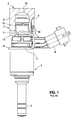
- FIG. 1 a valve in the form of an injection valve 1 for fuel injection systems of mixture-compression spark-ignited internal combustion engines in a side view.
- the fuel injection valve 1 is part of the fuel injection device.
- the fuel injection valve 1 which is designed in the form of a direct-injection injector for injecting fuel directly into a combustion chamber of the internal combustion engine, in a receiving bore of a cylinder head, not shown (cylinder head 9 in FIG. 2 ) built-in.
- a sealing ring 2 in particular of Teflon®, ensures optimum sealing of the fuel injection valve 1 with respect to the wall of the cylinder head.
- the fuel injection valve 1 has at its inlet end 3 a plug connection to a fuel rail (fuel rail) 4, which by a sealing ring 5 between a connecting piece 6 of the fuel distributor line 4, which is shown in section, and an inlet nozzle 7 of the fuel injection valve 1 is sealed.
- the fuel injection valve 1 is inserted into a receiving opening 12 of the relatively massive connection piece 6 of the fuel distribution line 4.
- the connecting piece 6 is, for example, in one piece from the actual fuel distributor line 4 and has upstream of the receiving opening 12 a smaller diameter flow opening 15 through which the flow of the fuel injection valve 1 takes place.
- the fuel injection valve 1 has an electrical connection plug 8 for the electrical contacting for actuating the fuel injection valve 1.
- a holding-down device 10 is provided between the fuel injection valve 1 and the connecting piece 6.
- the hold-down 10 is designed as a bow-shaped component, e.g. as punching-bending part.
- the hold-down device 10 has a part-ring-shaped base element 11, from which a hold-down bar 13 extends, which abuts against a downstream end face 14 of the connecting piece 6 on the fuel distributor line 4 in the installed state.
- FIG. 2 shows a partially illustrated fuel injection device in a second known embodiment.
- This schematic cross section through a high-pressure injection system illustrates that various design variants of the connecting piece 6 are conceivable.
- a fuel distributor line 4 is provided, which extends at an offset to the valve longitudinal axes of the fuel injection valves 1.
- the connecting piece 6 forms a connecting piece between the fuel injection valve 1 and the fuel distributor line 4, this connecting piece being fixedly connected to the fuel distributor line 4.
- the connecting piece 6 has, as in the in FIG. 1 As shown in the example, an opening, which is composed of a flow opening 15 and a receiving opening 12.
- the connecting piece 6 is otherwise similar cup-shaped ("Raikltasse").
- FIG. 3 shows a partially illustrated fuel injection device in a third known embodiment.
- This known solution is similar to the basic structure of the strong in FIG. 1 shown execution.
- the connection piece 6 does not come out of the fuel distributor line 4 in one piece. Rather, the connecting piece 6 is its own example deep-drawn cup-shaped component which is connected by means of joining (eg brazing) fixed to the fuel rail 4.
- the wall thickness of the connecting piece 6 is therefore significantly reduced, whereby the extension length of the flow opening 15 is low.
- the connecting piece 6 is fastened to the fuel distributor line 4 in such a way that the outflow opening 16 of the fuel distributor line 4, the flow opening 15 and the receiving opening 12 of the connecting piece 6 are aligned with one another.
- the fuel injection valves 1 are connected via a plug connection with the connecting piece 6 of the fuel distributor line 4.
- the connector is realized within a run as a rail cup connection piece 6, in which the fuel injection valve 1 is inserted.
- the sealing to the outside is carried out with an attached to the inlet nozzle 7 of the fuel injection valve 1 elastomeric sealing ring 5.
- proportional hydraulic forces are built up against the fuel injection valve 1 and the fuel manifold 4 via the voltage applied in the connecting piece 6 fuel pressure of the cross-sectional area. In today's typical designs, this is about 10 N / bar.
- the high-frequency component of 1 to 5 kHz is transmitted via the fuel injection valves 1 and the fuel distributor line 4 as structure-borne noise to the entire engine structure (inter alia cylinder head 9) and leads there to an unwanted sound radiation, which can lead to audible ticker noises.
- the highly dynamic pressure changes are largely kept away from the connecting piece 6 by being passed through the connecting piece 6 directly into the fuel distributor line 4, without triggering dynamic pressure fluctuations in the volume of the connecting piece 6.
- This is done with a pressure waveguide 20, which is tubular.
- the pressure waveguide 20 ensures that the formation of dynamic alternating forces is significantly reduced. The result is a reduced wear of the sealing rings 2, 5 and a significantly reduced noise.
- the slowly variable pressure build-up and dismantling is maintained, since at high load conditions, the force generated by the pressure still supports the holding down of the fuel injection valves 1 by means of hold-down 10 against the combustion pressure of the combustion chamber.
- the invention can also be implemented on a suction tube injection system.
- FIG. 4 shows a partial view of the fuel injection device in the region of the connection of the connecting piece 6 and the fuel injection valve 1 with the pressure wave guide 20 according to the invention in a schematic diagram, wherein the partial view of the embodiment according to FIG. 3 emanates.
- the pressure wave guide 20 is designed as a thin tube with a continuous longitudinal opening and with the Fuel injection valve 1 is firmly connected at its inlet end. Starting from the fuel injection valve 1, the pressure waveguide 20 protrudes in the upstream direction through the receiving opening 12, the flow opening 15 and the discharge opening 16 and slightly into the interior of the fuel distributor line 4.
- the pressure waveguide 20 thus connects the fuel injection valve 1 to the fuel distributor line 4 caused by the opening and closing of the fuel injection valve 1 pressure waves in the fuel passing through the pressure waveguide 20 on the volume of the receiving opening 12 of the connecting piece 6 over, without there pressure fluctuations and thus to generate alternating forces.
- a complete penetration of the discharge opening 16 through the pressure waveguide 20 is not a mandatory requirement.
- annular leakage gap 21 In the region of the discharge opening 16 of the fuel distributor line 4, which is penetrated by the pressure waveguide 20, an annular leakage gap 21 is formed.
- the leakage gap 21 between the pressure waveguide 20 and the wall of the discharge opening 16 allows a slow Druckauf- and -development in the connecting piece 6 according to the system pressure, so a static pressure compensation.
- This additional, non-tight connection combines the advantages of a real line connection of the fuel injectors 1 to the fuel rail 4 with the simple and inexpensive plug-in solution for connection to the fuel rail 4.
- FIG. 5 a first embodiment of a pressure waveguide 20 according to the invention is shown schematically.
- the pressure waveguide 20 for example, made of a media-resistant plastic (polyamide), which is attached to a fuel filter 22 of the fuel injection valve 1 by pressing or clipping or clipping. It is also conceivable to mold the pressure waveguide 20 in one piece with the plastic base body of the fuel filter 22.
- FIG. 6 a second embodiment of a pressure waveguide 20 according to the invention is shown schematically.
- the pressure waveguide 20 is made of a metal, for example, wherein the pressure waveguide 20 with a radially outwardly projecting flange 24, for example, to a connection sleeve 23 of the fuel injection valve 1 by gluing, welding, soldering, etc. is attached.
- a one-piece design is conceivable in which the pressure waveguide 20 emerges directly from a thermoformed or rotated connection sleeve 23.
- 20 grooves or groove or thread-like recesses may be formed on the outer circumference of the pressure waveguide.
- FIG. 7 shows a third embodiment of a pressure waveguide 20 according to the invention, in which case the pressure waveguide 20 is fixed to the fuel rail 4 and freely in the fuel injector 1, for example, in the fuel filter 22 hangs.
- the pressure waveguide 20 is, for example, by a snap, snap, clip connection o.ä. attached to the fuel rail 4.
- the fixed connection is made such that a leakage gap 21 is maintained.
- a second leakage gap 21 ' may also be provided, specifically between the pressure waveguide 20 and the fuel filter 22 or another component of the fuel injection valve 1 surrounding the pressure waveguide 20 FIGS.
- FIG. 8 and 9 show cross sections through the pressure waveguide 20 in the region of the leakage gap 21 ', wherein it can be seen that the outer surface of the pressure waveguide 20 is contoured.
- the outer surface of the pressure waveguide 20 may, for example, longitudinal ribs 24 ( FIG. 8 ) or longitudinal grooves or grooves 25 (FIG. FIG. 9 ) exhibit.
- FIGS. 5 to 9 shown pressure waveguide 20 are for a fuel injection device according to FIGS. 1 and 3 suitable. A complete penetration of the discharge opening 16 through the pressure waveguide 20 is not a mandatory requirement in these embodiments.
- FIG. 10 a fourth embodiment of a pressure waveguide 20 according to the invention is shown, said pressure waveguide 20 for a fuel injection device according to FIG. 2 suitable is.
- the pressure waveguide 20 is either attached to the fuel filter 22 of the fuel injection valve 1 by pressing or clipping on or integrally mitteilformt on the plastic body of the fuel filter 22.
- the pressure waveguide 20 can also be connected to the connection sleeve 23 of the fuel injection valve 1 or originate in one piece directly from a deep-drawn or rotated connection sleeve 23.
- the pressure waveguide 20 protrudes into only a part of the flow opening 15 of the connecting piece 6, but not up to lying at right angles to the discharge opening 16 of the fuel manifold 4. The positive effect of passing the dynamic pressure fluctuations in the volume of Receiving opening 12 of the connecting piece 6 is also achieved here.
Landscapes
- Engineering & Computer Science (AREA)
- Chemical & Material Sciences (AREA)
- Combustion & Propulsion (AREA)
- Mechanical Engineering (AREA)
- General Engineering & Computer Science (AREA)
- Fuel-Injection Apparatus (AREA)
Claims (10)
- Dispositif d'injection de carburant pour des installations d'injection de carburant de moteurs à combustion interne, en particulier pour l'injection directe de carburant dans une chambre de combustion, avec au moins un injecteur de carburant (1), une conduite de répartiteur de carburant (4) avec au moins un embout de raccordement (6), dans lequel l'injecteur de carburant (1) est introduit dans une ouverture de réception (12) de l'embout de raccordement (6) et la conduite de répartiteur de carburant (4) comporte une ouverture de sortie (16) pour la délivrance de carburant à l'injecteur de carburant (1), caractérisé en ce qu'il est prévu un guide d'ondes de pression (20) entre l'injecteur de carburant (1) et la conduite de répartiteur de carburant (4), de telle manière que des fluctuations dynamiques de la pression dans l'injecteur de carburant (1) puissent être largement déviées au volume de l'ouverture de réception (12) de l'embout de raccordement (6), dans lequel le guide d'ondes de pression (20) est fixé soit à l'injecteur de carburant (1) soit à la conduite de répartiteur de carburant (4), et dans lequel le guide d'ondes de pression (20) traverse au moins partiellement l'ouverture de sortie (16) de la conduite de répartiteur de carburant (4).
- Dispositif d'injection de carburant selon la revendication 1, caractérisé en ce que le guide d'ondes de pression (20) est réalisé sous forme de tube avec à l'intérieur une ouverture longitudinale continue.
- Dispositif d'injection de carburant selon la revendication 1 ou 2, caractérisé en ce que le guide d'ondes de pression (20) est fabriqué en métal ou en matière plastique.
- Dispositif d'injection de carburant selon la revendication 1, caractérisé en ce que le guide d'ondes de pression (20) est fixé à un filtre à carburant (22) ou à une douille de raccordement (23) de l'injecteur de carburant (1) ou il sort en une seule pièce hors du filtre à carburant (22) ou de la douille de raccordement (23) de l'injecteur de carburant (1).
- Dispositif d'injection de carburant selon la revendication 4, caractérisé en ce que le guide d'ondes de pression (20) peut être fixé au filtre à carburant (22) en l'enfonçant à la presse ou en le clipsant par l'intérieur ou par l'extérieur.
- Dispositif d'injection de carburant selon la revendication 1, caractérisé en ce que le guide d'ondes de pression (20) peut être fixé à la conduite de répartiteur de carburant (4) au moyen d'un assemblage par encliquetage, à ressort ou à clips.
- Dispositif d'injection de carburant selon l'une quelconque des revendications précédentes, caractérisé en ce que l'embout de raccordement (6) de la conduite de répartiteur de carburant (4) comporte, en amont de l'ouverture de sortie (12), une ouverture d'écoulement (15) de diamètre nettement plus petit par comparaison avec l'ouverture de sortie (12), qui est traversée au moins partiellement par le guide d'ondes de pression (20).
- Dispositif d'injection de carburant selon la revendication 1, caractérisé en ce que le guide d'ondes de pression (20) traverse au moins partiellement l'ouverture de sortie (16) de la conduite de répartiteur de carburant (4) avec un ajustement avec jeu, formant ainsi une fente de fuite (21).
- Dispositif d'injection de carburant selon la revendication 7, caractérisé en ce que le guide d'ondes de pression (20) traverse au moins partiellement l'ouverture d'écoulement (15) de l'embout de raccordement (6) de la conduite de répartiteur de carburant (4) avec un ajustement avec jeu, formant ainsi une fente de fuite (21).
- Dispositif d'injection de carburant selon la revendication 1, caractérisé en ce qu'une fente de fuite (21, 21') est formée entre le guide d'ondes de pression (20) et la paroi qui l'entoure au moyen de creux en forme de rayures ou de rainures ou de filet (24, 25) formés à la périphérie extérieure du guide d'ondes de pression (20).
Applications Claiming Priority (2)
| Application Number | Priority Date | Filing Date | Title |
|---|---|---|---|
| DE102007049357A DE102007049357A1 (de) | 2007-10-15 | 2007-10-15 | Brennstoffeinspritzvorrichtung |
| PCT/EP2007/063559 WO2009049687A1 (fr) | 2007-10-15 | 2007-12-07 | Dispositif d'injection de carburant |
Publications (2)
| Publication Number | Publication Date |
|---|---|
| EP2203639A1 EP2203639A1 (fr) | 2010-07-07 |
| EP2203639B1 true EP2203639B1 (fr) | 2015-07-08 |
Family
ID=39156553
Family Applications (1)
| Application Number | Title | Priority Date | Filing Date |
|---|---|---|---|
| EP07857303.7A Not-in-force EP2203639B1 (fr) | 2007-10-15 | 2007-12-07 | Dispositif d'injection de carburant |
Country Status (7)
| Country | Link |
|---|---|
| US (1) | US7931007B2 (fr) |
| EP (1) | EP2203639B1 (fr) |
| JP (1) | JP5145423B2 (fr) |
| KR (1) | KR101432566B1 (fr) |
| CN (1) | CN101828028B (fr) |
| DE (1) | DE102007049357A1 (fr) |
| WO (1) | WO2009049687A1 (fr) |
Families Citing this family (20)
| Publication number | Priority date | Publication date | Assignee | Title |
|---|---|---|---|---|
| US7942132B2 (en) * | 2008-07-17 | 2011-05-17 | Robert Bosch Gmbh | In-line noise filtering device for fuel system |
| ATE535706T1 (de) * | 2009-05-11 | 2011-12-15 | Continental Automotive Gmbh | Kraftstoffeinspritzdüse und kraftstoffeinspritzsystem |
| WO2012169990A2 (fr) * | 2010-05-04 | 2012-12-13 | Pathfinder Therapeutics, Inc. | Système et procédé d'appariement de surfaces abdominales à l'aide de pseudo-caractéristiques |
| DE102011075057A1 (de) * | 2011-05-02 | 2012-11-08 | Robert Bosch Gmbh | Brennstoffverteiler und System mit einem Brennstoffeinspritzventil |
| JP2013072416A (ja) * | 2011-09-29 | 2013-04-22 | Otics Corp | フューエルデリバリパイプ |
| JP5955198B2 (ja) | 2012-11-02 | 2016-07-20 | 株式会社ケーヒン | 直噴式燃料噴射弁の支持構造 |
| JP6074793B2 (ja) | 2012-11-05 | 2017-02-08 | 株式会社ケーヒン | 燃料噴射弁の支持構造 |
| JP6074794B2 (ja) | 2012-11-05 | 2017-02-08 | 株式会社ケーヒン | 燃料噴射弁の支持構造 |
| DE102012220491A1 (de) * | 2012-11-09 | 2014-05-15 | Robert Bosch Gmbh | Brennstoffeinspritzventil und Brennstoffeinspritzanlage mit einem Brennstoffeinspritzventil |
| DE102013200781A1 (de) * | 2013-01-18 | 2014-07-24 | Robert Bosch Gmbh | Brennstoffeinspritzanlage mit einer Brennstoff führenden Komponente, einem Brennstoffeinspritzventil und einer Verbindungsanordnung |
| JP2014196730A (ja) * | 2013-03-29 | 2014-10-16 | トヨタ自動車株式会社 | 燃料供給配管 |
| DE102013207368A1 (de) * | 2013-04-23 | 2014-10-23 | Robert Bosch Gmbh | Halter zur Befestigung eines Brennstoffverteilers an einer Brennkraftmaschine und Anlage mit solch einem Halter |
| EP2813699B1 (fr) * | 2013-06-14 | 2018-09-05 | FPT Motorenforschung AG | Agencement de tuyauterie de carburant type rampe commune dans des systèmes d'alimentation en carburant |
| CN104948277B (zh) * | 2015-06-30 | 2018-05-04 | 苏州派格丽减排系统有限公司 | 一种无气泵水冷喷嘴 |
| KR101938481B1 (ko) * | 2017-06-23 | 2019-01-14 | 주식회사 현대케피코 | 인젝터용 클립 |
| FR3083829B1 (fr) * | 2018-07-10 | 2021-01-08 | Senior Flexonics Blois Sas | Dispositif d'injection a rampe commune |
| FR3083830B1 (fr) * | 2018-07-16 | 2021-10-01 | Senior Flexonics Blois Sas | Dispositif d'injection a rampe commune |
| CN110848061B (zh) * | 2019-06-28 | 2025-02-18 | 潍柴动力股份有限公司 | 微泄漏装置及共轨管 |
| DE102019210142A1 (de) * | 2019-07-10 | 2021-01-14 | Robert Bosch Gmbh | Einspritzventil für ein Wassereinspritzsystem eines Verbrennungsmotors sowie Wassereinspritzsystem mit einem solchen Einspritzventil |
| CN112393895B (zh) * | 2019-08-14 | 2022-07-15 | 宝山钢铁股份有限公司 | 冷轧机精细冷却喷射阀动静特性参数测试装置及测试方法 |
Family Cites Families (29)
| Publication number | Priority date | Publication date | Assignee | Title |
|---|---|---|---|---|
| US4693223A (en) * | 1984-06-21 | 1987-09-15 | General Motors Corporation | Fuel injection valve connection |
| US5373824A (en) * | 1993-08-06 | 1994-12-20 | Ford Motor Company | Acoustical damping device for gaseous fueled automotive engines |
| US5394850A (en) * | 1993-11-19 | 1995-03-07 | Siemens Electric Limited | Top-feed fuel injector mounting in an integrated air-fuel system |
| DE4341368A1 (de) * | 1993-12-04 | 1995-06-08 | Bosch Gmbh Robert | Dämpferelement zur Dämpfung von Druckschwingungen |
| JPH08312495A (ja) * | 1995-05-11 | 1996-11-26 | Keihin Seiki Mfg Co Ltd | 電磁式燃料噴射弁 |
| JPH09151830A (ja) * | 1995-11-30 | 1997-06-10 | Mikuni Corp | 燃料噴射装置 |
| JP3831970B2 (ja) * | 1996-03-14 | 2006-10-11 | 株式会社デンソー | 内燃機関の燃料噴射装置 |
| US5785022A (en) * | 1997-05-28 | 1998-07-28 | Epic Technical Group, Inc. | Fuel injector post |
| JP4156147B2 (ja) * | 1999-10-05 | 2008-09-24 | 臼井国際産業株式会社 | フユーエルデリバリパイプ |
| GB2358898B (en) * | 1999-12-09 | 2002-04-24 | Usui Kokusai Sangyo Kk | Diesel engine fuel injection pipe |
| EP1278956B1 (fr) * | 2000-03-21 | 2005-12-07 | Siemens Aktiengesellschaft | Ensemble injecteur de carburant utilise pour installer un injecteur de carburant sur une rampe de carburant et pour assurer l'alignement de l'injecteur de carburant |
| DE10032678A1 (de) * | 2000-07-05 | 2002-01-17 | Daimler Chrysler Ag | Einspritzvorrichtung für eine Brennkraftmaschine |
| US20020043249A1 (en) * | 2000-10-16 | 2002-04-18 | Ki-Ho Lee | Fuel rail with intergal dampening features |
| JP4053340B2 (ja) * | 2002-04-18 | 2008-02-27 | 臼井国際産業株式会社 | フユーエルデリバリパイプ |
| JP4032385B2 (ja) * | 2002-04-22 | 2008-01-16 | 臼井国際産業株式会社 | フユーエルデリバリパイプ |
| JP2004028076A (ja) * | 2002-05-08 | 2004-01-29 | Usui Kokusai Sangyo Kaisha Ltd | フユーエルデリバリパイプ |
| US6905002B2 (en) * | 2002-06-21 | 2005-06-14 | International Engine Intellectual Property Company, Llc | Acoustic wave attenuator for a rail |
| US6742504B2 (en) * | 2002-06-21 | 2004-06-01 | International Engine Intellectual Property Company, Llc | Pressure wave attenuator for a rail |
| JP2004027964A (ja) * | 2002-06-25 | 2004-01-29 | Aisin Seiki Co Ltd | 車両用の燃料供給装置 |
| US6761150B2 (en) * | 2002-11-05 | 2004-07-13 | Millennium Industries Corp. | Fuel rail flow-feed pulse damper |
| JP2004211637A (ja) * | 2003-01-07 | 2004-07-29 | Denso Corp | 高圧燃料蓄圧器 |
| US6935314B2 (en) * | 2003-12-19 | 2005-08-30 | Millennium Industries Corp. | Fuel rail air damper |
| DE102004048401A1 (de) | 2004-10-01 | 2006-04-06 | Robert Bosch Gmbh | Niederhalter für eine Brennstoffeinspritzvorrichtung und Brennstoffeinspritzvorrichtung |
| DE102005026992A1 (de) | 2005-06-10 | 2006-12-14 | Robert Bosch Gmbh | Hochdruckspeicherraum mit integriertem Drossel- und Filterelement |
| US7093584B1 (en) * | 2005-08-19 | 2006-08-22 | Delphi Technologies, Inc. | Fuel injector noise mufflers |
| JP4442567B2 (ja) * | 2006-01-20 | 2010-03-31 | 株式会社デンソー | コモンレール |
| US7617991B2 (en) * | 2006-03-31 | 2009-11-17 | Delphi Technologies, Inc. | Injector fuel filter with built-in orifice for flow restriction |
| US7406946B1 (en) * | 2007-04-02 | 2008-08-05 | Hitachi, Ltd. | Method and apparatus for attenuating fuel pump noise in a direct injection internal combustion chamber |
| US7681553B2 (en) * | 2007-08-10 | 2010-03-23 | Pulsco, Inc. | Nested three chambers, fluid pulsation dampener |
-
2007
- 2007-10-15 DE DE102007049357A patent/DE102007049357A1/de not_active Withdrawn
- 2007-12-07 EP EP07857303.7A patent/EP2203639B1/fr not_active Not-in-force
- 2007-12-07 US US11/922,525 patent/US7931007B2/en not_active Expired - Fee Related
- 2007-12-07 WO PCT/EP2007/063559 patent/WO2009049687A1/fr not_active Ceased
- 2007-12-07 KR KR1020107008222A patent/KR101432566B1/ko not_active Expired - Fee Related
- 2007-12-07 JP JP2010529242A patent/JP5145423B2/ja not_active Expired - Fee Related
- 2007-12-07 CN CN200780101123.2A patent/CN101828028B/zh not_active Expired - Fee Related
Also Published As
| Publication number | Publication date |
|---|---|
| WO2009049687A1 (fr) | 2009-04-23 |
| KR101432566B1 (ko) | 2014-08-22 |
| JP5145423B2 (ja) | 2013-02-20 |
| CN101828028B (zh) | 2015-05-27 |
| JP2011501020A (ja) | 2011-01-06 |
| DE102007049357A1 (de) | 2009-04-16 |
| KR20100065193A (ko) | 2010-06-15 |
| CN101828028A (zh) | 2010-09-08 |
| US20100218742A1 (en) | 2010-09-02 |
| US7931007B2 (en) | 2011-04-26 |
| EP2203639A1 (fr) | 2010-07-07 |
Similar Documents
| Publication | Publication Date | Title |
|---|---|---|
| EP2203639B1 (fr) | Dispositif d'injection de carburant | |
| EP2189650B1 (fr) | Dispositif d'injection de carburant | |
| EP2286081B1 (fr) | Élément de retenue pour dispositif d'injection de carburant | |
| EP1906005A1 (fr) | Dispositif d'injection de carburant | |
| EP2948675A1 (fr) | Installation d'injection de carburant dotée d'un composant d'alimentation en carburant, d'un injecteur de carburant et d'une attache de suspension | |
| EP1442211B1 (fr) | Procede pour produire une conduite de reservoir de carburant comprenant une piece de raccordement precontrainte | |
| EP2948673B1 (fr) | Installation d'injection de carburant dotée d'un élément d'acheminement du carburant, d'un injecteur de carburant et d'un élément de liaison | |
| DE10256668A1 (de) | Stützelement | |
| DE102008042154A1 (de) | Brennstoffeinspritzventil | |
| EP2466108B1 (fr) | Soupape d'injection de combustible | |
| EP1893867B1 (fr) | Corps de chambre d'accumulation haute pression presentant des elements d'etranglement haute pression | |
| DE102013200922A1 (de) | Brennstoffeinspritzanlage mit einer Brennstoff führenden Komponente, einem Brennstoffeinspritzventil und einer Aufhängung | |
| DE102013200719A1 (de) | Brennstoffeinspritzanlage mit einer Brennstoff führenden Komponente, einem Brennstoffeinspritzventil und einem Verbindungselement | |
| DE102021212779A1 (de) | Brennstoffeinspritzventil | |
| DE102020213354A1 (de) | Brennstoffeinspritzventil | |
| DE102020213356A1 (de) | Brennstoffeinspritzventil | |
| DE102021213586A1 (de) | Brennstoffeinspritzventil | |
| DE102021214077A1 (de) | Brennstoffeinspritzventil | |
| DE102019216587A1 (de) | Brennstoffeinspritzventil | |
| DE102020202826A1 (de) | Brennstoffeinspritzventil | |
| DE102019131537A1 (de) | Vorrichtung zur Druckregelung in einer Kraftstoffzuführung eines Verbrennungsmotors mit einer Common-Rail-Einspritzung | |
| DE102005051005A1 (de) | Brennstoffeinspritzventil | |
| DE102019215138A1 (de) | Aufhängung zur Verbindung eines Anschlussstutzens eines Zumessventils mit einer Fluid führenden Komponente und Einspritzanlage mit solch einer Aufhängung | |
| WO2006048371A1 (fr) | Dispositif d'injection de carburant pour moteur a combustion interne |
Legal Events
| Date | Code | Title | Description |
|---|---|---|---|
| PUAI | Public reference made under article 153(3) epc to a published international application that has entered the european phase |
Free format text: ORIGINAL CODE: 0009012 |
|
| 17P | Request for examination filed |
Effective date: 20100528 |
|
| AK | Designated contracting states |
Kind code of ref document: A1 Designated state(s): AT BE BG CH CY CZ DE DK EE ES FI FR GB GR HU IE IS IT LI LT LU LV MC MT NL PL PT RO SE SI SK TR |
|
| AX | Request for extension of the european patent |
Extension state: AL BA HR MK RS |
|
| R17P | Request for examination filed (corrected) |
Effective date: 20100517 |
|
| DAX | Request for extension of the european patent (deleted) | ||
| 17Q | First examination report despatched |
Effective date: 20141104 |
|
| REG | Reference to a national code |
Ref country code: DE Ref legal event code: R079 Ref document number: 502007014048 Country of ref document: DE Free format text: PREVIOUS MAIN CLASS: F02M0055040000 Ipc: F02M0055020000 |
|
| GRAP | Despatch of communication of intention to grant a patent |
Free format text: ORIGINAL CODE: EPIDOSNIGR1 |
|
| RIC1 | Information provided on ipc code assigned before grant |
Ipc: F02M 69/46 20060101ALI20150326BHEP Ipc: F02M 61/14 20060101ALI20150326BHEP Ipc: F02M 61/16 20060101ALI20150326BHEP Ipc: F02M 55/02 20060101AFI20150326BHEP Ipc: F02M 55/04 20060101ALI20150326BHEP |
|
| INTG | Intention to grant announced |
Effective date: 20150413 |
|
| GRAS | Grant fee paid |
Free format text: ORIGINAL CODE: EPIDOSNIGR3 |
|
| GRAA | (expected) grant |
Free format text: ORIGINAL CODE: 0009210 |
|
| AK | Designated contracting states |
Kind code of ref document: B1 Designated state(s): AT BE BG CH CY CZ DE DK EE ES FI FR GB GR HU IE IS IT LI LT LU LV MC MT NL PL PT RO SE SI SK TR |
|
| REG | Reference to a national code |
Ref country code: GB Ref legal event code: FG4D Free format text: NOT ENGLISH |
|
| REG | Reference to a national code |
Ref country code: AT Ref legal event code: REF Ref document number: 735616 Country of ref document: AT Kind code of ref document: T Effective date: 20150715 Ref country code: CH Ref legal event code: EP |
|
| REG | Reference to a national code |
Ref country code: IE Ref legal event code: FG4D Free format text: LANGUAGE OF EP DOCUMENT: GERMAN |
|
| REG | Reference to a national code |
Ref country code: DE Ref legal event code: R096 Ref document number: 502007014048 Country of ref document: DE |
|
| REG | Reference to a national code |
Ref country code: NL Ref legal event code: MP Effective date: 20150708 |
|
| REG | Reference to a national code |
Ref country code: FR Ref legal event code: PLFP Year of fee payment: 9 |
|
| REG | Reference to a national code |
Ref country code: LT Ref legal event code: MG4D |
|
| PG25 | Lapsed in a contracting state [announced via postgrant information from national office to epo] |
Ref country code: LT Free format text: LAPSE BECAUSE OF FAILURE TO SUBMIT A TRANSLATION OF THE DESCRIPTION OR TO PAY THE FEE WITHIN THE PRESCRIBED TIME-LIMIT Effective date: 20150708 Ref country code: FI Free format text: LAPSE BECAUSE OF FAILURE TO SUBMIT A TRANSLATION OF THE DESCRIPTION OR TO PAY THE FEE WITHIN THE PRESCRIBED TIME-LIMIT Effective date: 20150708 Ref country code: GR Free format text: LAPSE BECAUSE OF FAILURE TO SUBMIT A TRANSLATION OF THE DESCRIPTION OR TO PAY THE FEE WITHIN THE PRESCRIBED TIME-LIMIT Effective date: 20151009 Ref country code: LV Free format text: LAPSE BECAUSE OF FAILURE TO SUBMIT A TRANSLATION OF THE DESCRIPTION OR TO PAY THE FEE WITHIN THE PRESCRIBED TIME-LIMIT Effective date: 20150708 |
|
| PG25 | Lapsed in a contracting state [announced via postgrant information from national office to epo] |
Ref country code: PT Free format text: LAPSE BECAUSE OF FAILURE TO SUBMIT A TRANSLATION OF THE DESCRIPTION OR TO PAY THE FEE WITHIN THE PRESCRIBED TIME-LIMIT Effective date: 20151109 Ref country code: IS Free format text: LAPSE BECAUSE OF FAILURE TO SUBMIT A TRANSLATION OF THE DESCRIPTION OR TO PAY THE FEE WITHIN THE PRESCRIBED TIME-LIMIT Effective date: 20151108 Ref country code: ES Free format text: LAPSE BECAUSE OF FAILURE TO SUBMIT A TRANSLATION OF THE DESCRIPTION OR TO PAY THE FEE WITHIN THE PRESCRIBED TIME-LIMIT Effective date: 20150708 Ref country code: SE Free format text: LAPSE BECAUSE OF FAILURE TO SUBMIT A TRANSLATION OF THE DESCRIPTION OR TO PAY THE FEE WITHIN THE PRESCRIBED TIME-LIMIT Effective date: 20150708 Ref country code: PL Free format text: LAPSE BECAUSE OF FAILURE TO SUBMIT A TRANSLATION OF THE DESCRIPTION OR TO PAY THE FEE WITHIN THE PRESCRIBED TIME-LIMIT Effective date: 20150708 |
|
| PGFP | Annual fee paid to national office [announced via postgrant information from national office to epo] |
Ref country code: FR Payment date: 20151218 Year of fee payment: 9 |
|
| REG | Reference to a national code |
Ref country code: DE Ref legal event code: R097 Ref document number: 502007014048 Country of ref document: DE |
|
| PG25 | Lapsed in a contracting state [announced via postgrant information from national office to epo] |
Ref country code: CZ Free format text: LAPSE BECAUSE OF FAILURE TO SUBMIT A TRANSLATION OF THE DESCRIPTION OR TO PAY THE FEE WITHIN THE PRESCRIBED TIME-LIMIT Effective date: 20150708 Ref country code: SK Free format text: LAPSE BECAUSE OF FAILURE TO SUBMIT A TRANSLATION OF THE DESCRIPTION OR TO PAY THE FEE WITHIN THE PRESCRIBED TIME-LIMIT Effective date: 20150708 Ref country code: EE Free format text: LAPSE BECAUSE OF FAILURE TO SUBMIT A TRANSLATION OF THE DESCRIPTION OR TO PAY THE FEE WITHIN THE PRESCRIBED TIME-LIMIT Effective date: 20150708 Ref country code: DK Free format text: LAPSE BECAUSE OF FAILURE TO SUBMIT A TRANSLATION OF THE DESCRIPTION OR TO PAY THE FEE WITHIN THE PRESCRIBED TIME-LIMIT Effective date: 20150708 |
|
| PLBE | No opposition filed within time limit |
Free format text: ORIGINAL CODE: 0009261 |
|
| STAA | Information on the status of an ep patent application or granted ep patent |
Free format text: STATUS: NO OPPOSITION FILED WITHIN TIME LIMIT |
|
| PG25 | Lapsed in a contracting state [announced via postgrant information from national office to epo] |
Ref country code: BE Free format text: LAPSE BECAUSE OF NON-PAYMENT OF DUE FEES Effective date: 20151231 Ref country code: RO Free format text: LAPSE BECAUSE OF FAILURE TO SUBMIT A TRANSLATION OF THE DESCRIPTION OR TO PAY THE FEE WITHIN THE PRESCRIBED TIME-LIMIT Effective date: 20150708 |
|
| 26N | No opposition filed |
Effective date: 20160411 |
|
| PG25 | Lapsed in a contracting state [announced via postgrant information from national office to epo] |
Ref country code: LU Free format text: LAPSE BECAUSE OF FAILURE TO SUBMIT A TRANSLATION OF THE DESCRIPTION OR TO PAY THE FEE WITHIN THE PRESCRIBED TIME-LIMIT Effective date: 20151207 Ref country code: MC Free format text: LAPSE BECAUSE OF FAILURE TO SUBMIT A TRANSLATION OF THE DESCRIPTION OR TO PAY THE FEE WITHIN THE PRESCRIBED TIME-LIMIT Effective date: 20150708 |
|
| REG | Reference to a national code |
Ref country code: CH Ref legal event code: PL |
|
| GBPC | Gb: european patent ceased through non-payment of renewal fee |
Effective date: 20151207 |
|
| PG25 | Lapsed in a contracting state [announced via postgrant information from national office to epo] |
Ref country code: SI Free format text: LAPSE BECAUSE OF FAILURE TO SUBMIT A TRANSLATION OF THE DESCRIPTION OR TO PAY THE FEE WITHIN THE PRESCRIBED TIME-LIMIT Effective date: 20150708 |
|
| REG | Reference to a national code |
Ref country code: IE Ref legal event code: MM4A |
|
| PG25 | Lapsed in a contracting state [announced via postgrant information from national office to epo] |
Ref country code: CH Free format text: LAPSE BECAUSE OF NON-PAYMENT OF DUE FEES Effective date: 20151231 Ref country code: IE Free format text: LAPSE BECAUSE OF NON-PAYMENT OF DUE FEES Effective date: 20151207 Ref country code: GB Free format text: LAPSE BECAUSE OF NON-PAYMENT OF DUE FEES Effective date: 20151207 Ref country code: LI Free format text: LAPSE BECAUSE OF NON-PAYMENT OF DUE FEES Effective date: 20151231 |
|
| REG | Reference to a national code |
Ref country code: AT Ref legal event code: MM01 Ref document number: 735616 Country of ref document: AT Kind code of ref document: T Effective date: 20151207 |
|
| PGFP | Annual fee paid to national office [announced via postgrant information from national office to epo] |
Ref country code: IT Payment date: 20161220 Year of fee payment: 10 |
|
| PG25 | Lapsed in a contracting state [announced via postgrant information from national office to epo] |
Ref country code: HU Free format text: LAPSE BECAUSE OF FAILURE TO SUBMIT A TRANSLATION OF THE DESCRIPTION OR TO PAY THE FEE WITHIN THE PRESCRIBED TIME-LIMIT; INVALID AB INITIO Effective date: 20071207 Ref country code: AT Free format text: LAPSE BECAUSE OF NON-PAYMENT OF DUE FEES Effective date: 20151207 Ref country code: BG Free format text: LAPSE BECAUSE OF FAILURE TO SUBMIT A TRANSLATION OF THE DESCRIPTION OR TO PAY THE FEE WITHIN THE PRESCRIBED TIME-LIMIT Effective date: 20150708 |
|
| PG25 | Lapsed in a contracting state [announced via postgrant information from national office to epo] |
Ref country code: NL Free format text: LAPSE BECAUSE OF FAILURE TO SUBMIT A TRANSLATION OF THE DESCRIPTION OR TO PAY THE FEE WITHIN THE PRESCRIBED TIME-LIMIT Effective date: 20150708 Ref country code: CY Free format text: LAPSE BECAUSE OF FAILURE TO SUBMIT A TRANSLATION OF THE DESCRIPTION OR TO PAY THE FEE WITHIN THE PRESCRIBED TIME-LIMIT Effective date: 20150708 |
|
| PG25 | Lapsed in a contracting state [announced via postgrant information from national office to epo] |
Ref country code: MT Free format text: LAPSE BECAUSE OF FAILURE TO SUBMIT A TRANSLATION OF THE DESCRIPTION OR TO PAY THE FEE WITHIN THE PRESCRIBED TIME-LIMIT Effective date: 20150708 Ref country code: TR Free format text: LAPSE BECAUSE OF FAILURE TO SUBMIT A TRANSLATION OF THE DESCRIPTION OR TO PAY THE FEE WITHIN THE PRESCRIBED TIME-LIMIT Effective date: 20150708 |
|
| REG | Reference to a national code |
Ref country code: FR Ref legal event code: ST Effective date: 20170831 |
|
| PG25 | Lapsed in a contracting state [announced via postgrant information from national office to epo] |
Ref country code: FR Free format text: LAPSE BECAUSE OF NON-PAYMENT OF DUE FEES Effective date: 20170102 |
|
| PG25 | Lapsed in a contracting state [announced via postgrant information from national office to epo] |
Ref country code: IT Free format text: LAPSE BECAUSE OF NON-PAYMENT OF DUE FEES Effective date: 20171207 |
|
| PGFP | Annual fee paid to national office [announced via postgrant information from national office to epo] |
Ref country code: DE Payment date: 20240227 Year of fee payment: 17 |
|
| REG | Reference to a national code |
Ref country code: DE Ref legal event code: R119 Ref document number: 502007014048 Country of ref document: DE |
|
| PG25 | Lapsed in a contracting state [announced via postgrant information from national office to epo] |
Ref country code: DE Free format text: LAPSE BECAUSE OF NON-PAYMENT OF DUE FEES Effective date: 20250701 |