EP2204121B1 - Vorrichtung zur Unterdrückung von Bewegungsartefakten in der medizinischen interventionellen Navigation - Google Patents
Vorrichtung zur Unterdrückung von Bewegungsartefakten in der medizinischen interventionellen Navigation Download PDFInfo
- Publication number
- EP2204121B1 EP2204121B1 EP09015744.7A EP09015744A EP2204121B1 EP 2204121 B1 EP2204121 B1 EP 2204121B1 EP 09015744 A EP09015744 A EP 09015744A EP 2204121 B1 EP2204121 B1 EP 2204121B1
- Authority
- EP
- European Patent Office
- Prior art keywords
- catheter
- mapping
- nodes
- measuring
- location
- Prior art date
- Legal status (The legal status is an assumption and is not a legal conclusion. Google has not performed a legal analysis and makes no representation as to the accuracy of the status listed.)
- Active
Links
Images

Classifications
-
- A—HUMAN NECESSITIES
- A61—MEDICAL OR VETERINARY SCIENCE; HYGIENE
- A61B—DIAGNOSIS; SURGERY; IDENTIFICATION
- A61B5/00—Measuring for diagnostic purposes; Identification of persons
- A61B5/72—Signal processing specially adapted for physiological signals or for diagnostic purposes
- A61B5/7203—Signal processing specially adapted for physiological signals or for diagnostic purposes for noise prevention, reduction or removal
- A61B5/7207—Signal processing specially adapted for physiological signals or for diagnostic purposes for noise prevention, reduction or removal of noise induced by motion artifacts
-
- A—HUMAN NECESSITIES
- A61—MEDICAL OR VETERINARY SCIENCE; HYGIENE
- A61B—DIAGNOSIS; SURGERY; IDENTIFICATION
- A61B5/00—Measuring for diagnostic purposes; Identification of persons
- A61B5/06—Devices, other than using radiation, for detecting or locating foreign bodies ; Determining position of diagnostic devices within or on the body of the patient
- A61B5/061—Determining position of a probe within the body employing means separate from the probe, e.g. sensing internal probe position employing impedance electrodes on the surface of the body
- A61B5/062—Determining position of a probe within the body employing means separate from the probe, e.g. sensing internal probe position employing impedance electrodes on the surface of the body using magnetic field
-
- A—HUMAN NECESSITIES
- A61—MEDICAL OR VETERINARY SCIENCE; HYGIENE
- A61B—DIAGNOSIS; SURGERY; IDENTIFICATION
- A61B18/00—Surgical instruments, devices or methods for transferring non-mechanical forms of energy to or from the body
- A61B18/04—Surgical instruments, devices or methods for transferring non-mechanical forms of energy to or from the body by heating
- A61B18/12—Surgical instruments, devices or methods for transferring non-mechanical forms of energy to or from the body by heating by passing a current through the tissue to be heated, e.g. high-frequency current
- A61B18/14—Probes or electrodes therefor
- A61B18/1492—Probes or electrodes therefor having a flexible, catheter-like structure, e.g. for heart ablation
-
- A—HUMAN NECESSITIES
- A61—MEDICAL OR VETERINARY SCIENCE; HYGIENE
- A61B—DIAGNOSIS; SURGERY; IDENTIFICATION
- A61B34/00—Computer-aided surgery; Manipulators or robots specially adapted for use in surgery
- A61B34/20—Surgical navigation systems; Devices for tracking or guiding surgical instruments, e.g. for frameless stereotaxis
-
- A—HUMAN NECESSITIES
- A61—MEDICAL OR VETERINARY SCIENCE; HYGIENE
- A61B—DIAGNOSIS; SURGERY; IDENTIFICATION
- A61B5/00—Measuring for diagnostic purposes; Identification of persons
- A61B5/06—Devices, other than using radiation, for detecting or locating foreign bodies ; Determining position of diagnostic devices within or on the body of the patient
- A61B5/061—Determining position of a probe within the body employing means separate from the probe, e.g. sensing internal probe position employing impedance electrodes on the surface of the body
- A61B5/063—Determining position of a probe within the body employing means separate from the probe, e.g. sensing internal probe position employing impedance electrodes on the surface of the body using impedance measurements
-
- A—HUMAN NECESSITIES
- A61—MEDICAL OR VETERINARY SCIENCE; HYGIENE
- A61B—DIAGNOSIS; SURGERY; IDENTIFICATION
- A61B5/00—Measuring for diagnostic purposes; Identification of persons
- A61B5/103—Measuring devices for testing the shape, pattern, colour, size or movement of the body or parts thereof, for diagnostic purposes
- A61B5/107—Measuring physical dimensions, e.g. size of the entire body or parts thereof
- A61B5/1076—Measuring physical dimensions, e.g. size of the entire body or parts thereof for measuring dimensions inside body cavities, e.g. using catheters
-
- A—HUMAN NECESSITIES
- A61—MEDICAL OR VETERINARY SCIENCE; HYGIENE
- A61B—DIAGNOSIS; SURGERY; IDENTIFICATION
- A61B5/00—Measuring for diagnostic purposes; Identification of persons
- A61B5/24—Detecting, measuring or recording bioelectric or biomagnetic signals of the body or parts thereof
- A61B5/25—Bioelectric electrodes therefor
- A61B5/279—Bioelectric electrodes therefor specially adapted for particular uses
- A61B5/28—Bioelectric electrodes therefor specially adapted for particular uses for electrocardiography [ECG]
- A61B5/283—Invasive
- A61B5/287—Holders for multiple electrodes, e.g. electrode catheters for electrophysiological study [EPS]
-
- A—HUMAN NECESSITIES
- A61—MEDICAL OR VETERINARY SCIENCE; HYGIENE
- A61B—DIAGNOSIS; SURGERY; IDENTIFICATION
- A61B5/00—Measuring for diagnostic purposes; Identification of persons
- A61B5/68—Arrangements of detecting, measuring or recording means, e.g. sensors, in relation to patient
- A61B5/6846—Arrangements of detecting, measuring or recording means, e.g. sensors, in relation to patient specially adapted to be brought in contact with an internal body part, i.e. invasive
- A61B5/6847—Arrangements of detecting, measuring or recording means, e.g. sensors, in relation to patient specially adapted to be brought in contact with an internal body part, i.e. invasive mounted on an invasive device
- A61B5/6852—Catheters
-
- A—HUMAN NECESSITIES
- A61—MEDICAL OR VETERINARY SCIENCE; HYGIENE
- A61B—DIAGNOSIS; SURGERY; IDENTIFICATION
- A61B5/00—Measuring for diagnostic purposes; Identification of persons
- A61B5/72—Signal processing specially adapted for physiological signals or for diagnostic purposes
- A61B5/7235—Details of waveform analysis
- A61B5/725—Details of waveform analysis using specific filters therefor, e.g. Kalman or adaptive filters
-
- A—HUMAN NECESSITIES
- A61—MEDICAL OR VETERINARY SCIENCE; HYGIENE
- A61B—DIAGNOSIS; SURGERY; IDENTIFICATION
- A61B8/00—Diagnosis using ultrasonic, sonic or infrasonic waves
- A61B8/08—Clinical applications
- A61B8/0833—Clinical applications involving detecting or locating foreign bodies or organic structures
- A61B8/0841—Clinical applications involving detecting or locating foreign bodies or organic structures for locating instruments
-
- A—HUMAN NECESSITIES
- A61—MEDICAL OR VETERINARY SCIENCE; HYGIENE
- A61B—DIAGNOSIS; SURGERY; IDENTIFICATION
- A61B17/00—Surgical instruments, devices or methods
- A61B2017/00681—Aspects not otherwise provided for
- A61B2017/00694—Aspects not otherwise provided for with means correcting for movement of or for synchronisation with the body
- A61B2017/00699—Aspects not otherwise provided for with means correcting for movement of or for synchronisation with the body correcting for movement caused by respiration, e.g. by triggering
-
- A—HUMAN NECESSITIES
- A61—MEDICAL OR VETERINARY SCIENCE; HYGIENE
- A61B—DIAGNOSIS; SURGERY; IDENTIFICATION
- A61B17/00—Surgical instruments, devices or methods
- A61B2017/00681—Aspects not otherwise provided for
- A61B2017/00694—Aspects not otherwise provided for with means correcting for movement of or for synchronisation with the body
- A61B2017/00703—Aspects not otherwise provided for with means correcting for movement of or for synchronisation with the body correcting for movement of heart, e.g. ECG-triggered
-
- A—HUMAN NECESSITIES
- A61—MEDICAL OR VETERINARY SCIENCE; HYGIENE
- A61B—DIAGNOSIS; SURGERY; IDENTIFICATION
- A61B18/00—Surgical instruments, devices or methods for transferring non-mechanical forms of energy to or from the body
- A61B2018/00315—Surgical instruments, devices or methods for transferring non-mechanical forms of energy to or from the body for treatment of particular body parts
- A61B2018/00345—Vascular system
- A61B2018/00351—Heart
- A61B2018/00357—Endocardium
-
- A—HUMAN NECESSITIES
- A61—MEDICAL OR VETERINARY SCIENCE; HYGIENE
- A61B—DIAGNOSIS; SURGERY; IDENTIFICATION
- A61B18/00—Surgical instruments, devices or methods for transferring non-mechanical forms of energy to or from the body
- A61B2018/00571—Surgical instruments, devices or methods for transferring non-mechanical forms of energy to or from the body for achieving a particular surgical effect
- A61B2018/00577—Ablation
-
- A—HUMAN NECESSITIES
- A61—MEDICAL OR VETERINARY SCIENCE; HYGIENE
- A61B—DIAGNOSIS; SURGERY; IDENTIFICATION
- A61B34/00—Computer-aided surgery; Manipulators or robots specially adapted for use in surgery
- A61B34/20—Surgical navigation systems; Devices for tracking or guiding surgical instruments, e.g. for frameless stereotaxis
- A61B2034/2046—Tracking techniques
- A61B2034/2051—Electromagnetic tracking systems
-
- A—HUMAN NECESSITIES
- A61—MEDICAL OR VETERINARY SCIENCE; HYGIENE
- A61B—DIAGNOSIS; SURGERY; IDENTIFICATION
- A61B34/00—Computer-aided surgery; Manipulators or robots specially adapted for use in surgery
- A61B34/20—Surgical navigation systems; Devices for tracking or guiding surgical instruments, e.g. for frameless stereotaxis
- A61B2034/2046—Tracking techniques
- A61B2034/2063—Acoustic tracking systems, e.g. using ultrasound
-
- A—HUMAN NECESSITIES
- A61—MEDICAL OR VETERINARY SCIENCE; HYGIENE
- A61B—DIAGNOSIS; SURGERY; IDENTIFICATION
- A61B34/00—Computer-aided surgery; Manipulators or robots specially adapted for use in surgery
- A61B34/20—Surgical navigation systems; Devices for tracking or guiding surgical instruments, e.g. for frameless stereotaxis
- A61B2034/2072—Reference field transducer attached to an instrument or patient
Definitions
- the present invention relates to an apparatus and system for mapping the location of a point within a body. More specifically, the present invention relates to an apparatus for mapping the location of a node, such as a distal end electrode of a catheter, disposed within a body and located at a point, which is desired to be tracked, through reference to a plurality of reference nodes, such as a plurality of electrodes disposed within a reference catheter, and interpolation between the node and the plurality of reference nodes. Further, the present invention, upon mapping, will filter out any motion artifacts which may distort the location and/or movement of the node.
- a node such as a distal end electrode of a catheter
- an element, or node, of a medical device may be tracked within the body of a patient by measuring electrical signals passing through tissues, as well as other anatomic structures, in the body, through a navigational system (sometimes called a location mapping system).
- the location of the node may also be tracked by other means, such as magnetic and ultrasound tracking means.
- intersecting electromagnetic fields may be utilized to track the location of one or more elements, such as one or more catheter tips (or, more accurately, one or more electrodes disposed on a plurality of catheters), which may be placed at a point within a body.
- a reference node at a known, fixed location may be employed to determine the location, in relation to the reference node and other parts of a patient's anatomy, of the node, or element, which corresponds to the location of a point within the body.
- U.S. Patent No. 5,297,549 entitled “Endocardial Mapping System,” issued on 29 March 1994 discloses a mapping system utilizing an array of electrodes placed in a heart.
- the shape of the chamber, and the location of the electrodes are determined via impedance plethysmography.
- electrical measurements taken from the electrode array and referenced to a surface contacting electrode are used to generate a three-dimensional map of electrical activity.
- a two-dimensional map of the electrical activity within the endocardial surface is computed.
- U.S. Patent No. 5,311,866 entitled “Heart Mapping Catheter,” issued on 17 May 1994, discloses a mapping catheter assembly.
- a lumen is provided to accept a catheter which includes a distal tip electrode assembly.
- an array of electrode sites are deformed into a spherical shape after the assembly is placed in a heart chamber.
- a reference electrode assembly is advanced into contact with the heart wall to provide calibration information for the array.
- U.S. Patent No. 5,553,61 1 entitled “Endocardial Measurement Method,” issued on 10 September 1996, discloses a method for taking a collection of measurements from a set of measurement electrodes in an effort to determine the position of a catheter in a heart chamber.
- U.S. Patent No. 5,662,108 entitled “Electrophysiology Mapping System,” issued on 02 September 1997, discloses a mapping catheter positioned in a heart chamber, in which active electrode sites are activated to impose an electric field within the chamber. The blood volume and wall motion modulates the electric field, which is detected by passive electrode sites on the preferred catheter.
- electrophysiology measurements, as well as geometry measurements can be taken from the passive electrodes and used to display a map of intrinsic heart activity.
- U.S. Patent No. 5,697,377 (and its progeny), entitled “Catheter Mapping System And Method,” issued on 16 December 1997, discloses a system and method for catheter location mapping.
- Three substantially orthogonal alternating signals are applied through the patient, directed substantially toward the area of interest to be mapped.
- a catheter equipped with at least a measuring electrode for cardiac procedures, is positioned at various locations either against the patient's heart wall, or within a coronary vein or artery.
- a voltage is sensed between the catheter tip and a reference electrode, preferably a surface electrode on the patient, which voltage signal has components corresponding to the three orthogonal applied current signals.
- U.S. Patent No. 5,983,126 entitled “Catheter Location System And Method,” issued on 09 November 1999, is a continuation of this reference.
- U.S. Patent No. 6,049,622 entitled “Graphic Navigational Guides For Accurate Image Orientation And Navigation,” issued on 11 April 2000, and discloses a method for the acquisition of image data having an attached spatial coordinate system. A navigational guide can then employ the coordinate system to indicate the orientation of the imaged object and the location of the viewer with respect to the imaged object.
- U.S. Patent No. 6,240,307 entitled “Endocardial Mapping System” (and its progeny) issued on 29 May 2001, discloses a system for mapping the electrical activity of a heart.
- the system includes a set of electrodes spaced from the heart wall and a set of electrodes in contact with the heart wall. Voltage measurements from the electrodes are used to generate three-dimensional and two-dimensional maps of the electrical activity of the heart.
- U.S. Patent Nos. 6,603,996 ; 6,647,617 ; 6,826,420 and 6,826,421 are divisionals of this reference.
- U.S. Patent Nos. 6,640,119 ; 6,728,562 and 6,990,370 are derivatives of this reference.
- U.S. Patent No. 6,556,695 entitled “Method For Producing High Resolution Real-Time Images, Of Structure And Function During Medical Procedures,” issued on 29 April 2003, discloses the acquisition of the images of a heart with a high resolution medical imaging system used to construct a dynamic high resolution 4D model.
- Real movements are actual, physical movements caused by the motion of a patient's body as a whole, or by parts of the body in relation to one another. For example, respiration causes expansion of the chest and consequent displacement of the organs contained within the chest cavity, including the heart. Additionally, “imaginary” movements may further add to the motion created by the physical movements described herein. For example, respiration may also alter the electrical impedance distribution of the body by the introduction of air into the chest cavity. The variations in the electrical field may result in readings that suggest additional motion by the node. For purposes of the present invention, these real and imaginary movements are collectively referred to as "motion artifacts.”
- Interventional navigational systems are used to map points within the body. These systems use electromagnetic mapping algorithms in conjunction with an image or model of the anatomical environment in which the tracked node (i.e. , the node whose location is to be tracked) operates. Such images are often derived from external imaging equipment currently known in the art, such as computed topography (“CT”) and magnetic resonance imaging (“MRI”) equipment.
- CT computed topography
- MRI magnetic resonance imaging
- the result is a surface model that may be interpolated from points in three dimensions (“3D") collected from an internal tracking node.
- 3D three dimensions
- US 5,713,946 discloses an apparatus and method for intrabody mapping.
- a set of more than two locatable catheters is placed at specific points in the heart chamber during the mapping procedures.
- the location of these reference catheters supplies the necessary information for proper three-dimensional correspondence of the heart chamber image and the mapping catheter location. It is preferred that three different catheters are left in known landmarks and a fourth catheter is used as the mapping/ablation catheter.
- WO 00/07501 discloses a method for localization.
- the localization system uses one or more ultrasound reference catheters.
- a mapping catheter and ablation catheters are also provided and displayed on a graphical display user interface.
- Each of the reference catheters carries a plurality of ultrasound transducers, with there being a total of at least four such transducers employed during the use of the system.
- one or more of the reference catheters is introduced into the heart or the surrounding musculature and is left in place for the duration of the procedure.
- the system measures the distances between each of the reference catheter transducers using the "time of flight" principle.
- US 2008/0221425 A1 discloses a method for registering a catheter navigation system to a three-dimensional image.
- An optional fixed reference electrode is placed on a second catheter, other than the mapping catheter having roving electrodes. It is mentioned to use the coronary sinus electrode or other fixed electrodes in the heart as a reference for measuring voltages and displacements, that is, the fixed reference electrode may define the origin of a coordinate system. This reference electrode is stationary. Voltage measurements provide the location in three-dimensional space of the electrodes inside the heart, such as roving electrodes. The voltages measured at the reference electrode are used to define the origin of the coordinate system, while the voltages measured at the roving electrodes are used to express the location of the roving electrodes relative to the origin. This document forms the closest prior art.
- the subject-matters of the dependent claims relate to further developments.
- a plurality of reference nodes are aligned at known points within a body. The location of a further node, distinct from the plurality of reference nodes, is determined relative to each of the plurality of reference nodes.
- Medical interventional navigation systems provide the ability to track the position of catheters, surgical tools and other devices inside a body. These systems typically use magnetic, electric, ultrasound or other radiation or energy sources or tracking means to determine the x, y and z coordinates of the devices within the body. When these devices are placed inside moving organs, such as the heart, the effect of any movement, or force, of those organs on the devices will most likely cause the devices to move. This effect is referred to herein as real movement, and can be illustrated in a respiration example, where the movement of the chest cavity will cause the movement of any organ contained within the chest cavity.
- these systems may also detect and report imaginary movement of the devices due to changes in the navigation field. For instance, in an impedance-based system, respiration of the body will alter the system conductance of the thorax, which will, in turn, alter the sensed electrical potential at the tracked device (i.e. , the device whose location is to be tracked). Because the system assumes that the navigation field is static, this change in sensed electrical potential will be perceived by the system as movement of the tracked device. In other words, although the tracked device may be completely stationary, the system will report that the tracked device is moving.
- the present invention provides a medical interventional navigation system that eliminates, or at least substantially reduces, both types of the aforementioned movements, or motion artifacts.
- the present invention acts to provide virtual stabilization of the tracked device, in which the appearance of stability of the tracked device is provided to a user of the medical interventional navigation system while the heart, for example, continues to beat and, consequently, move.
- such systems are used in conjunction with an image or model of the anatomical environment in which the tracked device operates. Further, such images are often derived from currently-known external imaging equipment, such as CT or MRI equipment. Additionally, such systems may have the ability to "collect,” or define, a geometry by moving the tracked device throughout a region desired to be mapped, and recording all the points the tracked device, which can be called a "mapping" device, has visited. This collection of points is often referred to as a cloud of points. In this way, a surface model can be subsequently "wrapped" around the collected points to provide a backdrop or context for the tracked device when the location thereof is displayed on a computer screen.
- ENSITETM NAVXTM integrated into the ENSITETM Advanced Mapping System by St. Jude Medical, Atrial Fibrillation Division, Inc., of Minnetonka, Minnesota.
- the ENSITETM NAVXTM system provides non-fluoroscopic navigation of both specialized and conventional electrophysiology catheters.
- the navigation methodology used therein is based on the principle that when an electric current is applied across a pair of cutaneous electrodes, a voltage gradient is created along the axis between the pair of cutaneous electrodes.
- cutaneous electrodes combining to comprise three (3) surface electrode pairs
- six (6) cutaneous electrodes are placed on the body of the patient: anterior to posterior (i.e ., the z- axis), left to right lateral ( i.e. , the y -axis) and superior (neck) to inferior (left leg) ( i.e. , the x -axis).
- anterior to posterior i.e ., the z- axis
- left to right lateral i.e. , the y -axis
- superior (neck) to inferior (left leg) i.e. , the x -axis
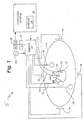
- FIG. 1 illustrates an exemplary embodiment of medical navigational system 5.
- Medical navigational system 5 will be briefly addressed herein, as it is one such system that may utilize the mapping techniques addressed in detail herein. Medical navigational system 5 is also discussed in detail in U.S. Patent No. 7,263,397 , which is issued on 28 August 2007.
- FIG. 1 in which patient 11 is depicted as an oval for clarity, three (3) sets of surface electrodes (as described herein) are illustrated as 18, 19 along the y -axis; 12, 14 along the x -axis; and 16, 22 along the z -axis.
- the assignment of the x , y, z axis to a particular direction is arbitrary and should not be construed to be limiting the invention.
- a further surface electrode 21, that acts as an electrical reference, which may be referred to as "belly" electrode 21, is also illustrated in FIG. 1 .
- Each surface electrode 12, 14, 16, 18, 19, 22 is independently coupled to multiplex switch 24.
- Heart 10 of patient 11 lies between the various pairs of surface electrodes 12, 14, 16, 18, 19, 22. Also illustrated in FIG.
- catheter 13 illustrating as including distal electrode 17 (again, for clarity). Multiple electrodes on catheter 13 may be used.
- any pair of surface electrodes 12, 14, 16, 18, 19, 22 may be selected for excitation by software running on computer system 20, which couples each surface electrode 12, 14, 16, 18, 19, 22 to signal generator 25.
- One pair of surface electrodes, for example, surface electrodes 18, 19, may be excited by signal generator 25 as that pair, in turn, generates an electric field in the body of patient 11 and, more accurately, in heart 10.
- remaining surface electrodes 12, 14, 16, 22 are preferably referenced to "belly" surface electrode 21, and the voltages impressed on remaining surface electrodes 12, 14, 16, 22 can be measured by analog-to-digital converter 26.
- Suitable low pass filtering of the digital data may be subsequently performed to remove electronic noise, for example, after suitable low pass filtering in filter 27.
- various patch electrodes 12, 14, 16, 18, 1 9, 22 can be divided into driven and non-driven surface electrode pairs. While one pair of surface electrodes are driven by signal generator 25, the remaining non-driven surface electrodes can be used as references to synthesize the orthogonal axes, described above.
- surface electrodes such as those discussed herein, may be connected to mapping systems such as the ENSITETM Advanced Mapping System described above, which sends an electrical signal through each pair of surface electrodes 12, 14, 16, 18, 19, 22 to create a voltage gradient along each orthogonal axis, forming a transthoracic electrical field.
- Conventional electrophysiology catheters e.g ., representative or measuring catheter 13
- an electrode disposed thereon e.g. , distal electrod or measuring electrode senses voltage, which is preferably timed to the creation of the gradient along each orthogonal axis.
- ENSITETM NAVXTM can then calculate the three-dimensional position of each electrode 17 on represent or measuring catheter 13.
- FIG. 2 illustrates representative or measuring catheter 13 disposed in heart 10.
- catheter 13 is illustrated as being located in left ventricle 50.
- catheter 13 is further illustrated as having additional electrodes 52, 54, 56. Since these electrodes lie in heart 10, the location process detects their location in heart.
- the ENSITETM Advanced Mapping System further comprises display 23 for displaying, in real-time, the location of electrodes 17, 52, 54, 56, as well as catheter 13.
- ENSITETM NAVXTM provides non-fluoroscopic navigation, mapping and creation of chamber models that are detailed and have accurate geometries.
- a physician may sweep catheter 13 across heart 10 to outline the structures by relaying signals to computer system 20, which then generates a three-dimensional model of heart 10.
- This model may be utilized for any appropriate purpose, such as assisting a physician in guiding an ablation catheter to a heart treatment location, cardiac mapping, etc.
- catheter 13 may be in a stationary position relative to the endocardial tissue, it may appear to be moving with respect to the static surface model.
- the operator desires to place the tip of catheter 1 3 on the endocardium to create a lesion, facilitating the delivery of radio frequency (RF) energy or radiation.
- RF radio frequency
- a mapping function may be defined as: f : R 3 ⁇ R 3 such that the mapping goes from the raw, unstabilized coordinates to stabilized coordinates, then providing a method to eliminate motion artifacts can be equated to solving the above mapping function.
- the mapping function can further be defined by finding the transformation that takes the current position of each electrode 17, 52, 54, 56 on catheter 13 and compares it with a set of constant positions, such as those set forth by catheter 29, which includes electrode 31.
- each of those electrodes can be used to generate input/output samples from which to solve the mapping function.
- the current observed position of the electrode represents the input and the initialized constant position represents the output.
- x i , y i i 1, N Typical assumptions that mapping should be continuous and smooth are assumed.
- the constant positions can be arbitrarily defined in numerous fashions.
- Reference catheter 29 comprises main shaft 58, having a proximal end and a distal end, through which leads may pass to various electrodes.
- Reference catheter 29 comprises reference electrode, or reference node, 31, provided at or near the distal end of reference catheter 29.
- reference node 31 may be an electrode capable of detecting and measuring fluctuations in an electromagnetic field.
- reference catheter 29 is provided with a plurality of other reference nodes 60, 62, 64 dispersed along its length. Similar to reference node 31, other reference nodes 60, 62, 64 may also be electrodes capable of detecting and measuring electromagnetic fields.
- Reference catheter 29 may be any type of catheter with electrodes.
- reference catheter 29 may comprise a mapping catheter, an intracardiac echocardiography ("ICE") catheter, and/or a pacemaker (e.g., a pacemaker with at least one electrode linked to the ENSITETM NAVXTM system).
- ICE intracardiac echocardiography
- pacemaker e.g., a pacemaker with at least one electrode linked to the ENSITETM NAVXTM system.
- surface electrodes 12, 14, 16, 18, 19, 22 may be applied externally to the body, in the manner described above.
- surface electrodes 12, 14, 16, 18, 19, 22 are used to create three (3) orthogonal potential fields.
- Reference nodes 31, 60, 62, 64 of reference catheter 29 measure the electrical potential at the location of the electrode which has been imposed by the cutaneous electrodes which have been modulated by the various body tissues to map the location of reference catheter 29 with respect to all three orthogonal axes, and therefore the location of reference catheter 29 in heart 10.
- a second, measuring catheter 13 likewise may measure its own position by measuring the same electromagnetic fields using reference catheter 29 and reference nodes 31, 60, 62, 64.
- reference catheter 29 is placed in a fixed, known location (or alternately, a location that can be substantially definitively ascertained).
- reference catheter 29 may be placed in the coronary sinus, where it is unlikely to shift, and can provide a good reference point relative to heart 10.
- the coronary sinus is mentioned in detail as one location for reference catheter 29, reference catheter 29 may be placed anywhere in the heart so long as its location is fixed.
- Software resident on computer system 20 can receive the inputs of both reference catheter 29 and catheter 13, and may then interpolate a more precise location of catheter 13 within the body.
- reference nodes 31, 60, 62, 64 of reference catheter 29 occupy a series of locations in three dimensions with respect to heart 10
- the motion of reference nodes 31, 60, 62, 64 will be complementary to the movement of heart 10 due to beating, respiration and other phenomena, i.e. , the motion artifacts. Therefore, if the locations of reference nodes 31, 60, 62, 64 are defined to be fixed, then motion artifacts may be eliminated between measuring electrode 17 and heart 10.
- reference catheter 29 may be placed in the vicinity of the working environment, which in the example herein, means within the vicinity of heart 10.
- the position of reference catheter 29 may be tracked and, after its location has been definitively ascertained, the motion of any other catheters in the working environment may also be determined, relative to the position of reference catheter 29.
- the position of reference catheter 29 is defined to be stationary, and has the effect of negating any motion artifacts of other catheters in the vicinity when those motion artifacts are negligible with respect to the actual movement of reference catheter 29. As the separation between reference catheter 29 and any tracked catheter element increases, the effects of the motion artifacts, described above, may likewise increase.
- a constant position of reference catheter 29 may be used as the constant position. If the motion of reference catheter 29 is sampled over time, the mean position of reference catheter 29, and more specifically the nodes 31, 60, 62, 64 on reference catheter 29, could be used as the constant position.
- a point when used to map points near and within heart 10, a point could be taken at a specific cardiac phase, such as an end diastole. The mapping could then be defined such that a different constant position is chosen for each point in time in the cardiac phase of the heart.
- a secondary or external location system may be employed to define the constant reference location. For example, a primary system that employs electrical impedance as its navigation system may use a magnetic location system to provide the constant reference location.
- the present invention utilizes a plurality of nodes or electrodes 31, 60, 62, 64 resident on reference catheter 29 to enhance the location accuracy and mapping, and to correct for defects inherent in using only one measuring catheter.
- the various inputs from the multiple electrodes 31, 60, 62, 64 may be utilized to create a static model of the location of reference catheter 29 in the body or with respect to a particular organ, such as heart 10.
- the use of multiple nodes defines a broader fixed location, and a wider frame of motion in which a tracked catheter may operate without increased motion artifacts.
- Each of the multiple nodes comprising the multi-point reference system of the present invention are impedance-based nodes, magnetic-based nodes, or optical-based nodes.
- all of the nodes making up the multi-point reference system of the present invention may be of the same type.
- the present invention is an extension to the use of a single node or electrode as a position reference which is common in current utilization of such systems.
- a single positional reference has the capability of eliminating only translation of the reference frame, whereas the present invention has the potential to eliminate higher order changes in the reference frame such as rotation, scale, and most generally deformations.
- One method of creating a static model of heart 10 from the inputs received from electrodes 31, 60, 62, 64 on reference catheter 29 may be to use a thin-plate splines algorithm.
- the thin-plate splines algorithm is a method of interpolation between a set of control points.
- the thin-plate splines algorithm minimizes a factor analogous to the bending energy of a thin metal plate which is forced to pass through the reference points.
- the thin-plate splines algorithm is the sum of a set of weighted basis functions centered at each reference point, where the basis function is typically: r 2 log r 2 where r is the radial distance of an input point from the particular basis function center.
- a regularization parameter ⁇ may be introduced into the linear algebraic equations to determine the thin-plate splines solution to create a smoother solution. If a regularization parameter is used in this context, the control points would not pass through the constant reference positions perfectly and therefore would not stabilize the model space entirely. This would represent a tradeoff of stabilization of the model versus a more robust solution that would be less sensitive to such things as random or other position errors that may be impressed on the location data of the reference catheter.
- radial basis function networks may be utilized to perform mapping functions to map the position of reference catheter 29 to a fixed position relative to heart 10 or other elements of the body.
- undesirable motion artifacts may be minimized by mapping the position of a fixed catheter or catheters to a fixed position.
- the location of all the catheters being tracked (both stationary and non-stationary) are processed with the computed mapping transformation, thus stabilizing the model reference frame.
- these transformations may require computation at each time point, modern computer hardware is sufficient to realize the computational load, which may be reduced by sampling fewer reference nodes on reference catheter 29.
- the computational load may also be reduced by reducing the frequency at which the mapping function is computed.
- the previously computed mapping function may be used if the catheter electrodes have not moved significantly from their previous location.
- mapping methods and functions described herein are illustrative, and are not intended to limit the scope of the present invention. Rather, any method of function regression which may be used to determine a mapping function from a set of samples is disclosed by the present invention.
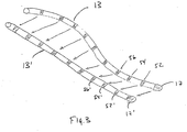
- FIG. 3 illustrates an exemplary illustration of the mapping of catheter 13, as illustrated in actual position with heart 10, to static position, referenced as 13', when employing the thin splines algorithm described herein.
- Static position 13' may, for example, be displayed on display 23 of computer system 20. Further, static position 13' may include static positions of each electrode present on catheter 13. The static position of each electrode is referenced as the reference number of each electrode primed.
- a feature of the invention is the definition of reference catheter 10 to occupy a known location.
- the coronary sinus is disclosed as a location, other locations may also be suitable.
- a high right atrium catheter and a right ventricle lead could replace or supplement electrode points in the coronary sinus and provide reference points which span more of the volume and dimensions of the heart.
Landscapes
- Health & Medical Sciences (AREA)
- Life Sciences & Earth Sciences (AREA)
- Engineering & Computer Science (AREA)
- Surgery (AREA)
- Public Health (AREA)
- Biomedical Technology (AREA)
- Heart & Thoracic Surgery (AREA)
- Medical Informatics (AREA)
- Molecular Biology (AREA)
- Animal Behavior & Ethology (AREA)
- General Health & Medical Sciences (AREA)
- Veterinary Medicine (AREA)
- Physics & Mathematics (AREA)
- Biophysics (AREA)
- Pathology (AREA)
- Nuclear Medicine, Radiotherapy & Molecular Imaging (AREA)
- Human Computer Interaction (AREA)
- Cardiology (AREA)
- Physiology (AREA)
- Signal Processing (AREA)
- Artificial Intelligence (AREA)
- Computer Vision & Pattern Recognition (AREA)
- Psychiatry (AREA)
- Robotics (AREA)
- Plasma & Fusion (AREA)
- Otolaryngology (AREA)
- Dentistry (AREA)
- Oral & Maxillofacial Surgery (AREA)
- Radiology & Medical Imaging (AREA)
- Measurement And Recording Of Electrical Phenomena And Electrical Characteristics Of The Living Body (AREA)
Claims (11)
- Vorrichtung zum Abbilden eines Orts eines Punkts innerhalb eines Körpers, wobei die Vorrichtung aufweist:einen Referenzkatheter (29), der in dem Körper platziert und mit einem Positionsreferenzknoten (31) und einer Mehrzahl von sekundären Referenzknoten (60, 62, 64) entlang dessen Länge versehen ist, wobei der Positionsreferenzknoten (31) und die Mehrzahl von sekundären Referenzknoten (60, 62, 64) Elektroden oder magnetbasierte Knoten sind;einen Messkatheter (13), der mit einer Mehrzahl von Messknoten (17, 52, 54, 56) versehen ist;ein Computersystem (20), das konfiguriert ist zum Empfangen von Eingaben der Knoten von beiden, dem Referenzkatheter (29) und dem Messkatheter (13);wobei das Computersystem (20) konfiguriert ist zum:Bestimmen der Position des Positionsreferenzknotens (31) innerhalb des Körpers,Lokalisieren der Mehrzahl von sekundären Referenzknoten (60, 62, 64) relativ zu dem Positionsreferenzknoten (31);Definieren einer Abbildungsfunktion von unbearbeiteten, instabilen Koordinaten zu stabilisieren Koordinaten, um so Bewegungsartefakte zu eliminieren, indem eine Transformation gefunden wird, die gegenwärtige Positionen von jedem der Mehrzahl von Messknoten (17, 52, 54, 56) auf dem Messkatheter (13) in dem Körper nimmt und diese mit einem Satz von konstanten Positionen vergleicht, die festgelegt sind durch bestimmte Positionen des Positionsreferenzknotens (31) und die Orte der Mehrzahl von sekundären Referenzknoten (60, 62, 64) wie durch den Referenzkatheter (29) festgelegt;Interpolieren eines Orts eines Punkts innerhalb des Körpers durch die Abbildungsfunktion, indem die Eingaben von den mehreren Referenzknoten (31, 60, 62, 64) des Referenzkatheters (29) und von dem Messkatheter (13) verwendet werden, wobei die Interpolation eine Ausrichtung des Messkatheters (13) aufweist relativ zu mindestens einem der sekundären Referenzknoten (60, 62, 64) und dem Positionsreferenzknoten (31).
- Vorrichtung nach Anspruch 1, bei der die Referenzknoten (31, 60, 62, 64) auf einem einzelnen Katheter (29) ausgerichtet sind.
- Vorrichtung nach Anspruch 1, bei der die Referenzknoten (31, 60, 62, 64) auf separaten Kathetern ausgerichtet sind.
- Vorrichtung nach einem der vorangegangenen Ansprüche, bei der das Abbilden ein Messen der Spannung an einem Punkt in einem Potentialgradienten zwischen einem Paar von Elektroden aufweist.
- Vorrichtung nach Anspruch 4, bei der die Position des Positionsreferenzknotens (31) und der sekundären Referenzknoten (60, 62, 64) bestimmt wird durch Messen von mindestens einem Potentialgradienten, der durch den Körper verläuft.
- Vorrichtung nach Anspruch 2 oder 3, bei der das Abbilden durch ein Magnetmittel bestimmt wird.
- Vorrichtung nach Anspruch 2 oder 3, bei der das Abbilden durch ein Ultraschallmittel bestimmt wird.
- Vorrichtung nach Anspruch 2 oder 3, bei der das Abbilden durch ein elektrisches Impedanzmittel bestimmt wird.
- Vorrichtung nach einem der vorangegangenen Ansprüche, bei der ein Thin-Plate-Spline-Algorithmus verwendet wird zur Durchführung der Interpolation.
- Vorrichtung nach einem der Ansprüche 1 bis 8, bei der ein radialbasiertes Funktionsnetzwerk verwendet wird zur Durchführung der Interpolation.
- Medizinisches Navigations- oder Abbildungssystem (5) mit einer Vorrichtung nach einem der Ansprüche 1 bis 10.
Applications Claiming Priority (1)
| Application Number | Priority Date | Filing Date | Title |
|---|---|---|---|
| US12/347,167 US9610118B2 (en) | 2008-12-31 | 2008-12-31 | Method and apparatus for the cancellation of motion artifacts in medical interventional navigation |
Publications (2)
| Publication Number | Publication Date |
|---|---|
| EP2204121A1 EP2204121A1 (de) | 2010-07-07 |
| EP2204121B1 true EP2204121B1 (de) | 2018-05-09 |
Family
ID=42126445
Family Applications (1)
| Application Number | Title | Priority Date | Filing Date |
|---|---|---|---|
| EP09015744.7A Active EP2204121B1 (de) | 2008-12-31 | 2009-12-18 | Vorrichtung zur Unterdrückung von Bewegungsartefakten in der medizinischen interventionellen Navigation |
Country Status (2)
| Country | Link |
|---|---|
| US (2) | US9610118B2 (de) |
| EP (1) | EP2204121B1 (de) |
Families Citing this family (17)
| Publication number | Priority date | Publication date | Assignee | Title |
|---|---|---|---|---|
| US9585586B2 (en) | 2006-12-29 | 2017-03-07 | St. Jude Medical, Atrial Fibrillation Division, Inc. | Navigational reference dislodgement detection method and system |
| US9320570B2 (en) * | 2007-12-28 | 2016-04-26 | St. Jude Medical, Atrial Fibrillation Division, Inc. | System and method for preventing collateral damage with interventional medical procedures |
| US8900150B2 (en) | 2008-12-30 | 2014-12-02 | St. Jude Medical, Atrial Fibrillation Division, Inc. | Intracardiac imaging system utilizing a multipurpose catheter |
| CN103220970B (zh) * | 2010-12-17 | 2016-03-09 | 圣犹达医疗用品电生理部门有限公司 | 导航参考点偏移检测方法和系统 |
| US9560988B2 (en) * | 2010-12-29 | 2017-02-07 | St. Jude Medical, Atrial Fibrillation Division, Inc. | System and method for rendering an image of an elongate medical device |
| US20130137963A1 (en) * | 2011-11-29 | 2013-05-30 | Eric S. Olson | System and method for automatically initializing or initiating a motion compensation algorithm |
| US10588543B2 (en) * | 2012-05-23 | 2020-03-17 | Biosense Webster (Israel), Ltd. | Position sensing using electric dipole fields |
| US9895079B2 (en) * | 2012-09-26 | 2018-02-20 | Biosense Webster (Israel) Ltd. | Electropotential mapping |
| GB2524080B (en) * | 2014-03-14 | 2019-03-13 | David Bye Edwin | Measuring and recording body electrical potentials |
| EP3157617B1 (de) * | 2014-06-19 | 2018-04-11 | Cardiac Pacemakers, Inc. | Barorezeptor-abbildungssystem |
| JP7157074B2 (ja) | 2016-12-20 | 2022-10-19 | コーニンクレッカ フィリップス エヌ ヴェ | 医療機器、特に心臓カテーテルのためのナビゲーション・プラットフォーム |
| WO2018115200A1 (en) * | 2016-12-20 | 2018-06-28 | Koninklijke Philips N.V. | Navigation platform for a medical device, particularly an intracardiac catheter |
| WO2018136733A1 (en) * | 2017-01-19 | 2018-07-26 | St. Jude Medical, Cardiology Division, Inc. | System and method for re-registration of localization system after shift/drift |
| US20190336198A1 (en) | 2018-05-03 | 2019-11-07 | Farapulse, Inc. | Systems, devices, and methods for ablation using surgical clamps |
| CN116327352A (zh) | 2018-05-07 | 2023-06-27 | 波士顿科学医学有限公司 | 心外膜消融导管 |
| US11185274B2 (en) * | 2018-06-18 | 2021-11-30 | Biosense Webster (Israel) Ltd. | Identifying orthogonal sets of active current location (ACL) patches |
| US12542209B2 (en) | 2021-01-25 | 2026-02-03 | Biosense Webster (Israel) Ltd. | Automatic catheter stability determination |
Family Cites Families (92)
| Publication number | Priority date | Publication date | Assignee | Title |
|---|---|---|---|---|
| US4951682A (en) * | 1988-06-22 | 1990-08-28 | The Cleveland Clinic Foundation | Continuous cardiac output by impedance measurements in the heart |
| US6405072B1 (en) * | 1991-01-28 | 2002-06-11 | Sherwood Services Ag | Apparatus and method for determining a location of an anatomical target with reference to a medical apparatus |
| US5156151A (en) * | 1991-02-15 | 1992-10-20 | Cardiac Pathways Corporation | Endocardial mapping and ablation system and catheter probe |
| US5699796A (en) | 1993-01-29 | 1997-12-23 | Cardima, Inc. | High resolution intravascular signal detection |
| US5944712A (en) * | 1992-03-02 | 1999-08-31 | Medtronic Ave, Inc. | Catheter size designation system |
| US5295484A (en) | 1992-05-19 | 1994-03-22 | Arizona Board Of Regents For And On Behalf Of The University Of Arizona | Apparatus and method for intra-cardiac ablation of arrhythmias |
| US5341807A (en) | 1992-06-30 | 1994-08-30 | American Cardiac Ablation Co., Inc. | Ablation catheter positioning system |
| US5662108A (en) * | 1992-09-23 | 1997-09-02 | Endocardial Solutions, Inc. | Electrophysiology mapping system |
| US5297549A (en) | 1992-09-23 | 1994-03-29 | Endocardial Therapeutics, Inc. | Endocardial mapping system |
| US5391199A (en) * | 1993-07-20 | 1995-02-21 | Biosense, Inc. | Apparatus and method for treating cardiac arrhythmias |
| US5409000A (en) * | 1993-09-14 | 1995-04-25 | Cardiac Pathways Corporation | Endocardial mapping and ablation system utilizing separately controlled steerable ablation catheter with ultrasonic imaging capabilities and method |
| WO1995010979A1 (en) | 1993-10-19 | 1995-04-27 | Ep Technologies, Inc. | Locating accessory pathways in the heart |
| WO1995020348A1 (en) | 1994-01-28 | 1995-08-03 | Ep Technologies, Inc. | Matching electrical characteristics and propagation velocities to locate ablation sites |
| US5447529A (en) | 1994-01-28 | 1995-09-05 | Philadelphia Heart Institute | Method of using endocardial impedance for determining electrode-tissue contact, appropriate sites for arrhythmia ablation and tissue heating during ablation |
| US5462545A (en) | 1994-01-31 | 1995-10-31 | New England Medical Center Hospitals, Inc. | Catheter electrodes |
| EP0767628B1 (de) | 1994-06-27 | 2004-01-14 | Boston Scientific Limited | Nichtlineare regelsysteme zur erwärmung und zum abtragen von körpergewebe |
| US5999840A (en) | 1994-09-01 | 1999-12-07 | Massachusetts Institute Of Technology | System and method of registration of three-dimensional data sets |
| US5643255A (en) | 1994-12-12 | 1997-07-01 | Hicor, Inc. | Steerable catheter with rotatable tip electrode and method of use |
| US5817022A (en) | 1995-03-28 | 1998-10-06 | Sonometrics Corporation | System for displaying a 2-D ultrasound image within a 3-D viewing environment |
| DE69631681T2 (de) | 1995-10-06 | 2004-07-29 | Cordis Webster, Inc., Diamond Bar | Elektroden-katheter mit geteilter spitze |
| US5823955A (en) | 1995-11-20 | 1998-10-20 | Medtronic Cardiorhythm | Atrioventricular valve tissue ablation catheter and method |
| JPH1033535A (ja) | 1996-07-30 | 1998-02-10 | Toshiba Corp | 超音波ドプラ診断装置および超音波ドプラ診断の方法 |
| US6091995A (en) | 1996-11-08 | 2000-07-18 | Surx, Inc. | Devices, methods, and systems for shrinking tissues |
| DE59813142D1 (de) | 1997-04-01 | 2005-12-01 | Axel Muntermann | Vorrichtung zur erfassung des katheter-gewebekontaktes sowie von wechselwirkungen mit dem gewebe bei der katheterablation |
| US5904653A (en) | 1997-05-07 | 1999-05-18 | General Electric Company | Method and apparatus for three-dimensional ultrasound imaging combining intensity data with color flow velocity or power data |
| US6490474B1 (en) * | 1997-08-01 | 2002-12-03 | Cardiac Pathways Corporation | System and method for electrode localization using ultrasound |
| US5836990A (en) | 1997-09-19 | 1998-11-17 | Medtronic, Inc. | Method and apparatus for determining electrode/tissue contact |
| US7094215B2 (en) | 1997-10-02 | 2006-08-22 | Arthrocare Corporation | Systems and methods for electrosurgical tissue contraction |
| US6106460A (en) | 1998-03-26 | 2000-08-22 | Scimed Life Systems, Inc. | Interface for controlling the display of images of diagnostic or therapeutic instruments in interior body regions and related data |
| US6059778A (en) | 1998-05-05 | 2000-05-09 | Cardiac Pacemakers, Inc. | RF ablation apparatus and method using unipolar and bipolar techniques |
| US7263397B2 (en) * | 1998-06-30 | 2007-08-28 | St. Jude Medical, Atrial Fibrillation Division, Inc. | Method and apparatus for catheter navigation and location and mapping in the heart |
| US7806829B2 (en) | 1998-06-30 | 2010-10-05 | St. Jude Medical, Atrial Fibrillation Division, Inc. | System and method for navigating an ultrasound catheter to image a beating heart |
| US6950689B1 (en) | 1998-08-03 | 2005-09-27 | Boston Scientific Scimed, Inc. | Dynamically alterable three-dimensional graphical model of a body region |
| US6346124B1 (en) | 1998-08-25 | 2002-02-12 | University Of Florida | Autonomous boundary detection system for echocardiographic images |
| US6139498A (en) | 1998-12-29 | 2000-10-31 | Ge Diasonics Israel, Ltd. | Ultrasound system performing simultaneous parallel computer instructions |
| US6556695B1 (en) * | 1999-02-05 | 2003-04-29 | Mayo Foundation For Medical Education And Research | Method for producing high resolution real-time images, of structure and function during medical procedures |
| WO2001006917A1 (en) * | 1999-07-26 | 2001-02-01 | Super Dimension Ltd. | Linking of an intra-body tracking system to external reference coordinates |
| US6235018B1 (en) | 1999-10-29 | 2001-05-22 | Cryoflex, Inc. | Method and apparatus for monitoring cryosurgical operations |
| US6584343B1 (en) * | 2000-03-15 | 2003-06-24 | Resolution Medical, Inc. | Multi-electrode panel system for sensing electrical activity of the heart |
| US6856826B2 (en) * | 2000-04-28 | 2005-02-15 | Ge Medical Systems Global Technology Company, Llc | Fluoroscopic tracking and visualization system |
| US20020183739A1 (en) | 2001-03-30 | 2002-12-05 | Long Gary L. | Endoscopic ablation system with sealed sheath |
| US6773402B2 (en) | 2001-07-10 | 2004-08-10 | Biosense, Inc. | Location sensing with real-time ultrasound imaging |
| US7187964B2 (en) | 2001-09-27 | 2007-03-06 | Dirar S. Khoury | Cardiac catheter imaging system |
| US20030063781A1 (en) * | 2001-09-28 | 2003-04-03 | Koninklijke Philips Electronics N.V. | Face recognition from a temporal sequence of face images |
| WO2003039659A1 (en) | 2001-10-18 | 2003-05-15 | Mi In Nara Co., Ltd. | Personal thermotherapeutic apparatus having chiropratic function |
| US20030093067A1 (en) * | 2001-11-09 | 2003-05-15 | Scimed Life Systems, Inc. | Systems and methods for guiding catheters using registered images |
| CA2478250C (en) | 2002-03-20 | 2011-09-06 | Novadaq Technologies Inc. | System and method for visualizing fluid flow through vessels |
| US7001383B2 (en) | 2002-10-21 | 2006-02-21 | Biosense, Inc. | Real-time monitoring and mapping of ablation lesion formation in the heart |
| US7697972B2 (en) | 2002-11-19 | 2010-04-13 | Medtronic Navigation, Inc. | Navigation system for cardiac therapies |
| JP4714677B2 (ja) * | 2003-03-14 | 2011-06-29 | コーニンクレッカ フィリップス エレクトロニクス エヌ ヴィ | 動き補正された三次元ボリュームイメージング方法 |
| US20040220471A1 (en) | 2003-04-29 | 2004-11-04 | Yitzhack Schwartz | Method and device for transseptal facilitation using location system |
| US20050065434A1 (en) * | 2003-09-22 | 2005-03-24 | Bavaro Vincent P. | Polymeric marker with high radiopacity for use in medical devices |
| EP1720480A1 (de) | 2004-03-05 | 2006-11-15 | Hansen Medical, Inc. | Roboter-kathetersystem |
| MXPA06012485A (es) * | 2004-04-29 | 2007-06-19 | Landmark Graphics Corp | Sistema y metodo para aproximar una superficie editable. |
| WO2006068271A1 (ja) | 2004-12-24 | 2006-06-29 | Yd, Ltd | 心臓弁データ計測方法および装置 |
| US8611983B2 (en) * | 2005-01-18 | 2013-12-17 | Philips Electronics Ltd | Method and apparatus for guiding an instrument to a target in the lung |
| CN100445488C (zh) | 2005-08-01 | 2008-12-24 | 邱则有 | 一种现浇砼成型用空腔构件 |
| US8038625B2 (en) * | 2005-09-15 | 2011-10-18 | St. Jude Medical, Atrial Fibrillation Division, Inc. | System and method for three-dimensional mapping of electrophysiology information |
| US8303505B2 (en) | 2005-12-02 | 2012-11-06 | Abbott Cardiovascular Systems Inc. | Methods and apparatuses for image guided medical procedures |
| US10362959B2 (en) | 2005-12-06 | 2019-07-30 | St. Jude Medical, Atrial Fibrillation Division, Inc. | System and method for assessing the proximity of an electrode to tissue in a body |
| US8369922B2 (en) | 2005-12-06 | 2013-02-05 | St. Jude Medical Atrial Fibrillation Division, Inc. | Method for displaying catheter electrode-tissue contact in electro-anatomic mapping and navigation system |
| US8403925B2 (en) | 2006-12-06 | 2013-03-26 | St. Jude Medical, Atrial Fibrillation Division, Inc. | System and method for assessing lesions in tissue |
| US9612142B2 (en) | 2006-04-27 | 2017-04-04 | General Electric Company | Method and system for measuring flow through a heart valve |
| US7539532B2 (en) | 2006-05-12 | 2009-05-26 | Bao Tran | Cuffless blood pressure monitoring appliance |
| US7505810B2 (en) | 2006-06-13 | 2009-03-17 | Rhythmia Medical, Inc. | Non-contact cardiac mapping, including preprocessing |
| EP2068716B1 (de) | 2006-10-02 | 2011-02-09 | Hansen Medical, Inc. | System für dreidimensionale ultraschall-abbildung |
| CN101523237B (zh) | 2006-10-13 | 2015-01-14 | 皇家飞利浦电子股份有限公司 | 采用灰度级反转的3d超声彩色流成像 |
| US7831076B2 (en) | 2006-12-08 | 2010-11-09 | Biosense Webster, Inc. | Coloring electroanatomical maps to indicate ultrasound data acquisition |
| CN103222846B (zh) | 2007-01-19 | 2017-04-26 | 桑尼布鲁克健康科学中心 | 用于成像探头的扫描机构 |
| WO2008091583A2 (en) | 2007-01-23 | 2008-07-31 | Dtherapeutics, Llc | Image-based extraction for vascular trees |
| JP5639764B2 (ja) | 2007-03-08 | 2014-12-10 | シンク−アールエックス,リミティド | 運動する器官と共に使用するイメージング及びツール |
| US10433929B2 (en) * | 2007-03-09 | 2019-10-08 | St. Jude Medical, Atrial Fibrillation Division, Inc. | System and method for local deformable registration of a catheter navigation system to image data or a model |
| US20080249395A1 (en) | 2007-04-06 | 2008-10-09 | Yehoshua Shachar | Method and apparatus for controlling catheter positioning and orientation |
| US8428690B2 (en) | 2007-05-16 | 2013-04-23 | General Electric Company | Intracardiac echocardiography image reconstruction in combination with position tracking system |
| US8213693B1 (en) | 2007-05-16 | 2012-07-03 | General Electric Company | System and method to track and navigate a tool through an imaged subject |
| WO2009032421A2 (en) | 2007-07-27 | 2009-03-12 | Meridian Cardiovascular Systems, Inc. | Image guided intracardiac catheters |
| US7663754B2 (en) | 2007-10-12 | 2010-02-16 | Interactive Flow Studies Llc | Fluid flow visualization and analysis |
| US20090177089A1 (en) | 2008-01-04 | 2009-07-09 | Assaf Govari | Three-dimensional image reconstruction using doppler ultrasound |
| US8494608B2 (en) | 2008-04-18 | 2013-07-23 | Medtronic, Inc. | Method and apparatus for mapping a structure |
| JP5366612B2 (ja) | 2008-05-20 | 2013-12-11 | 株式会社東芝 | 画像処理装置、画像処理方法および画像処理プログラム |
| WO2010030904A2 (en) | 2008-09-11 | 2010-03-18 | Mayo Foundation For Medical Education And Research | Central core multifunctional cardiac devices |
| US9089287B2 (en) | 2008-12-30 | 2015-07-28 | St. Jude Medical, Atrial Fibrillation Division, Inc. | Image-guided ablation system and method for monitoring an ablation procedure |
| US8755203B2 (en) | 2008-12-30 | 2014-06-17 | Dialog Semiconductor Inc. | Valley-mode switching schemes for switching power converters |
| US20100168572A1 (en) | 2008-12-30 | 2010-07-01 | Sliwa John W | Apparatus and Methods for Acoustic Monitoring of Ablation Procedures |
| WO2010144402A2 (en) | 2009-06-08 | 2010-12-16 | Surgivision, Inc. | Mri-guided surgical systems with preset scan planes |
| US9119951B2 (en) | 2009-10-12 | 2015-09-01 | Kona Medical, Inc. | Energetic modulation of nerves |
| US20110142316A1 (en) | 2009-10-29 | 2011-06-16 | Ge Wang | Tomography-Based and MRI-Based Imaging Systems |
| US8454589B2 (en) | 2009-11-20 | 2013-06-04 | St. Jude Medical, Atrial Fibrillation Division, Inc. | System and method for assessing effective delivery of ablation therapy |
| US9082182B2 (en) | 2009-11-25 | 2015-07-14 | Dental Imaging Technologies Corporation | Extracting patient motion vectors from marker positions in x-ray images |
| US20120158011A1 (en) | 2010-12-16 | 2012-06-21 | Sandhu Kulbir S | Proximity sensor interface in a robotic catheter system |
| US10524765B2 (en) | 2010-12-27 | 2020-01-07 | St. Jude Medical, Atrial Fibrillation Division, Inc. | Refinement of an anatomical model using ultrasound |
| US20120172724A1 (en) | 2010-12-31 | 2012-07-05 | Hill Anthony D | Automatic identification of intracardiac devices and structures in an intracardiac echo catheter image |
-
2008
- 2008-12-31 US US12/347,167 patent/US9610118B2/en active Active
-
2009
- 2009-12-18 EP EP09015744.7A patent/EP2204121B1/de active Active
-
2017
- 2017-02-21 US US15/437,479 patent/US20170224284A1/en not_active Abandoned
Non-Patent Citations (1)
| Title |
|---|
| None * |
Also Published As
| Publication number | Publication date |
|---|---|
| US20100168558A1 (en) | 2010-07-01 |
| US9610118B2 (en) | 2017-04-04 |
| US20170224284A1 (en) | 2017-08-10 |
| EP2204121A1 (de) | 2010-07-07 |
Similar Documents
| Publication | Publication Date | Title |
|---|---|---|
| US9610118B2 (en) | Method and apparatus for the cancellation of motion artifacts in medical interventional navigation | |
| US20210153770A1 (en) | Catheter navigation using impedance and magnetic field measurements | |
| US12295669B2 (en) | Systems and methods for performing localization within a body | |
| US10945633B2 (en) | Automated catalog and system for correction of inhomogeneous fields | |
| KR100686477B1 (ko) | 삼차원적으로 재구성되는 신체내 기관의 벡터 매핑 및 디스플레이 방법 | |
| US11918334B2 (en) | Impedance transformation model for estimating catheter locations | |
| KR20080106861A (ko) | 움직임 보상을 갖는 심장내 로케이션 시스템 | |
| CN102036606A (zh) | 测绘结构的方法和装置 | |
| CN109998534B (zh) | 心外膜标测 | |
| EP3505061B1 (de) | Verbesserung der leistung der impedanzbasierten positionsverfolgung mithilfe von hauptkomponentenanalyse | |
| US8948476B2 (en) | Determination of cardiac geometry responsive to doppler based imaging of blood flow characteristics | |
| US20230074429A1 (en) | Respiration compensation | |
| IL266912A (en) | Identify orthogonal sets of position stickers using active current | |
| US20220020228A1 (en) | Systems and methods for modifying geometry surface models using electrophysiology measurements |
Legal Events
| Date | Code | Title | Description |
|---|---|---|---|
| PUAI | Public reference made under article 153(3) epc to a published international application that has entered the european phase |
Free format text: ORIGINAL CODE: 0009012 |
|
| AK | Designated contracting states |
Kind code of ref document: A1 Designated state(s): AT BE BG CH CY CZ DE DK EE ES FI FR GB GR HR HU IE IS IT LI LT LU LV MC MK MT NL NO PL PT RO SE SI SK SM TR |
|
| AX | Request for extension of the european patent |
Extension state: AL BA RS |
|
| 17P | Request for examination filed |
Effective date: 20101221 |
|
| 17Q | First examination report despatched |
Effective date: 20111027 |
|
| RIC1 | Information provided on ipc code assigned before grant |
Ipc: A61B 5/06 20060101ALI20171025BHEP Ipc: A61B 5/042 20060101AFI20171025BHEP Ipc: A61B 34/20 20160101ALI20171025BHEP Ipc: A61B 5/107 20060101ALI20171025BHEP Ipc: A61B 5/00 20060101ALI20171025BHEP Ipc: A61B 18/14 20060101ALI20171025BHEP Ipc: A61B 17/00 20060101ALN20171025BHEP |
|
| GRAP | Despatch of communication of intention to grant a patent |
Free format text: ORIGINAL CODE: EPIDOSNIGR1 |
|
| RIC1 | Information provided on ipc code assigned before grant |
Ipc: A61B 34/20 20160101ALI20171102BHEP Ipc: A61B 5/06 20060101ALI20171102BHEP Ipc: A61B 5/107 20060101ALI20171102BHEP Ipc: A61B 17/00 20060101ALN20171102BHEP Ipc: A61B 18/14 20060101ALI20171102BHEP Ipc: A61B 5/00 20060101ALI20171102BHEP Ipc: A61B 5/042 20060101AFI20171102BHEP |
|
| INTG | Intention to grant announced |
Effective date: 20171201 |
|
| GRAS | Grant fee paid |
Free format text: ORIGINAL CODE: EPIDOSNIGR3 |
|
| GRAA | (expected) grant |
Free format text: ORIGINAL CODE: 0009210 |
|
| AK | Designated contracting states |
Kind code of ref document: B1 Designated state(s): AT BE BG CH CY CZ DE DK EE ES FI FR GB GR HR HU IE IS IT LI LT LU LV MC MK MT NL NO PL PT RO SE SI SK SM TR |
|
| REG | Reference to a national code |
Ref country code: GB Ref legal event code: FG4D |
|
| REG | Reference to a national code |
Ref country code: CH Ref legal event code: EP Ref country code: AT Ref legal event code: REF Ref document number: 996772 Country of ref document: AT Kind code of ref document: T Effective date: 20180515 |
|
| REG | Reference to a national code |
Ref country code: IE Ref legal event code: FG4D |
|
| REG | Reference to a national code |
Ref country code: DE Ref legal event code: R096 Ref document number: 602009052186 Country of ref document: DE |
|
| REG | Reference to a national code |
Ref country code: NL Ref legal event code: MP Effective date: 20180509 |
|
| REG | Reference to a national code |
Ref country code: LT Ref legal event code: MG4D |
|
| PG25 | Lapsed in a contracting state [announced via postgrant information from national office to epo] |
Ref country code: LT Free format text: LAPSE BECAUSE OF FAILURE TO SUBMIT A TRANSLATION OF THE DESCRIPTION OR TO PAY THE FEE WITHIN THE PRESCRIBED TIME-LIMIT Effective date: 20180509 Ref country code: ES Free format text: LAPSE BECAUSE OF FAILURE TO SUBMIT A TRANSLATION OF THE DESCRIPTION OR TO PAY THE FEE WITHIN THE PRESCRIBED TIME-LIMIT Effective date: 20180509 Ref country code: NO Free format text: LAPSE BECAUSE OF FAILURE TO SUBMIT A TRANSLATION OF THE DESCRIPTION OR TO PAY THE FEE WITHIN THE PRESCRIBED TIME-LIMIT Effective date: 20180809 Ref country code: FI Free format text: LAPSE BECAUSE OF FAILURE TO SUBMIT A TRANSLATION OF THE DESCRIPTION OR TO PAY THE FEE WITHIN THE PRESCRIBED TIME-LIMIT Effective date: 20180509 Ref country code: SE Free format text: LAPSE BECAUSE OF FAILURE TO SUBMIT A TRANSLATION OF THE DESCRIPTION OR TO PAY THE FEE WITHIN THE PRESCRIBED TIME-LIMIT Effective date: 20180509 Ref country code: BG Free format text: LAPSE BECAUSE OF FAILURE TO SUBMIT A TRANSLATION OF THE DESCRIPTION OR TO PAY THE FEE WITHIN THE PRESCRIBED TIME-LIMIT Effective date: 20180809 |
|
| PG25 | Lapsed in a contracting state [announced via postgrant information from national office to epo] |
Ref country code: GR Free format text: LAPSE BECAUSE OF FAILURE TO SUBMIT A TRANSLATION OF THE DESCRIPTION OR TO PAY THE FEE WITHIN THE PRESCRIBED TIME-LIMIT Effective date: 20180810 Ref country code: NL Free format text: LAPSE BECAUSE OF FAILURE TO SUBMIT A TRANSLATION OF THE DESCRIPTION OR TO PAY THE FEE WITHIN THE PRESCRIBED TIME-LIMIT Effective date: 20180509 Ref country code: HR Free format text: LAPSE BECAUSE OF FAILURE TO SUBMIT A TRANSLATION OF THE DESCRIPTION OR TO PAY THE FEE WITHIN THE PRESCRIBED TIME-LIMIT Effective date: 20180509 Ref country code: LV Free format text: LAPSE BECAUSE OF FAILURE TO SUBMIT A TRANSLATION OF THE DESCRIPTION OR TO PAY THE FEE WITHIN THE PRESCRIBED TIME-LIMIT Effective date: 20180509 |
|
| REG | Reference to a national code |
Ref country code: AT Ref legal event code: MK05 Ref document number: 996772 Country of ref document: AT Kind code of ref document: T Effective date: 20180509 |
|
| PG25 | Lapsed in a contracting state [announced via postgrant information from national office to epo] |
Ref country code: AT Free format text: LAPSE BECAUSE OF FAILURE TO SUBMIT A TRANSLATION OF THE DESCRIPTION OR TO PAY THE FEE WITHIN THE PRESCRIBED TIME-LIMIT Effective date: 20180509 Ref country code: EE Free format text: LAPSE BECAUSE OF FAILURE TO SUBMIT A TRANSLATION OF THE DESCRIPTION OR TO PAY THE FEE WITHIN THE PRESCRIBED TIME-LIMIT Effective date: 20180509 Ref country code: DK Free format text: LAPSE BECAUSE OF FAILURE TO SUBMIT A TRANSLATION OF THE DESCRIPTION OR TO PAY THE FEE WITHIN THE PRESCRIBED TIME-LIMIT Effective date: 20180509 Ref country code: RO Free format text: LAPSE BECAUSE OF FAILURE TO SUBMIT A TRANSLATION OF THE DESCRIPTION OR TO PAY THE FEE WITHIN THE PRESCRIBED TIME-LIMIT Effective date: 20180509 Ref country code: SK Free format text: LAPSE BECAUSE OF FAILURE TO SUBMIT A TRANSLATION OF THE DESCRIPTION OR TO PAY THE FEE WITHIN THE PRESCRIBED TIME-LIMIT Effective date: 20180509 Ref country code: CZ Free format text: LAPSE BECAUSE OF FAILURE TO SUBMIT A TRANSLATION OF THE DESCRIPTION OR TO PAY THE FEE WITHIN THE PRESCRIBED TIME-LIMIT Effective date: 20180509 Ref country code: PL Free format text: LAPSE BECAUSE OF FAILURE TO SUBMIT A TRANSLATION OF THE DESCRIPTION OR TO PAY THE FEE WITHIN THE PRESCRIBED TIME-LIMIT Effective date: 20180509 |
|
| REG | Reference to a national code |
Ref country code: DE Ref legal event code: R097 Ref document number: 602009052186 Country of ref document: DE |
|
| PG25 | Lapsed in a contracting state [announced via postgrant information from national office to epo] |
Ref country code: SM Free format text: LAPSE BECAUSE OF FAILURE TO SUBMIT A TRANSLATION OF THE DESCRIPTION OR TO PAY THE FEE WITHIN THE PRESCRIBED TIME-LIMIT Effective date: 20180509 |
|
| PGFP | Annual fee paid to national office [announced via postgrant information from national office to epo] |
Ref country code: FR Payment date: 20181119 Year of fee payment: 10 Ref country code: IT Payment date: 20181213 Year of fee payment: 10 Ref country code: GB Payment date: 20181129 Year of fee payment: 10 |
|
| PLBE | No opposition filed within time limit |
Free format text: ORIGINAL CODE: 0009261 |
|
| STAA | Information on the status of an ep patent application or granted ep patent |
Free format text: STATUS: NO OPPOSITION FILED WITHIN TIME LIMIT |
|
| 26N | No opposition filed |
Effective date: 20190212 |
|
| PG25 | Lapsed in a contracting state [announced via postgrant information from national office to epo] |
Ref country code: SI Free format text: LAPSE BECAUSE OF FAILURE TO SUBMIT A TRANSLATION OF THE DESCRIPTION OR TO PAY THE FEE WITHIN THE PRESCRIBED TIME-LIMIT Effective date: 20180509 |
|
| REG | Reference to a national code |
Ref country code: CH Ref legal event code: PL |
|
| PG25 | Lapsed in a contracting state [announced via postgrant information from national office to epo] |
Ref country code: MC Free format text: LAPSE BECAUSE OF FAILURE TO SUBMIT A TRANSLATION OF THE DESCRIPTION OR TO PAY THE FEE WITHIN THE PRESCRIBED TIME-LIMIT Effective date: 20180509 Ref country code: LU Free format text: LAPSE BECAUSE OF NON-PAYMENT OF DUE FEES Effective date: 20181218 |
|
| REG | Reference to a national code |
Ref country code: IE Ref legal event code: MM4A |
|
| REG | Reference to a national code |
Ref country code: BE Ref legal event code: MM Effective date: 20181231 |
|
| PG25 | Lapsed in a contracting state [announced via postgrant information from national office to epo] |
Ref country code: IE Free format text: LAPSE BECAUSE OF NON-PAYMENT OF DUE FEES Effective date: 20181218 |
|
| PG25 | Lapsed in a contracting state [announced via postgrant information from national office to epo] |
Ref country code: BE Free format text: LAPSE BECAUSE OF NON-PAYMENT OF DUE FEES Effective date: 20181231 |
|
| PG25 | Lapsed in a contracting state [announced via postgrant information from national office to epo] |
Ref country code: LI Free format text: LAPSE BECAUSE OF NON-PAYMENT OF DUE FEES Effective date: 20181231 Ref country code: CH Free format text: LAPSE BECAUSE OF NON-PAYMENT OF DUE FEES Effective date: 20181231 |
|
| PG25 | Lapsed in a contracting state [announced via postgrant information from national office to epo] |
Ref country code: MT Free format text: LAPSE BECAUSE OF NON-PAYMENT OF DUE FEES Effective date: 20181218 |
|
| PG25 | Lapsed in a contracting state [announced via postgrant information from national office to epo] |
Ref country code: TR Free format text: LAPSE BECAUSE OF FAILURE TO SUBMIT A TRANSLATION OF THE DESCRIPTION OR TO PAY THE FEE WITHIN THE PRESCRIBED TIME-LIMIT Effective date: 20180509 |
|
| PG25 | Lapsed in a contracting state [announced via postgrant information from national office to epo] |
Ref country code: PT Free format text: LAPSE BECAUSE OF FAILURE TO SUBMIT A TRANSLATION OF THE DESCRIPTION OR TO PAY THE FEE WITHIN THE PRESCRIBED TIME-LIMIT Effective date: 20180509 |
|
| PG25 | Lapsed in a contracting state [announced via postgrant information from national office to epo] |
Ref country code: CY Free format text: LAPSE BECAUSE OF FAILURE TO SUBMIT A TRANSLATION OF THE DESCRIPTION OR TO PAY THE FEE WITHIN THE PRESCRIBED TIME-LIMIT Effective date: 20180509 Ref country code: HU Free format text: LAPSE BECAUSE OF FAILURE TO SUBMIT A TRANSLATION OF THE DESCRIPTION OR TO PAY THE FEE WITHIN THE PRESCRIBED TIME-LIMIT; INVALID AB INITIO Effective date: 20091218 Ref country code: MK Free format text: LAPSE BECAUSE OF NON-PAYMENT OF DUE FEES Effective date: 20180509 |
|
| PG25 | Lapsed in a contracting state [announced via postgrant information from national office to epo] |
Ref country code: IS Free format text: LAPSE BECAUSE OF FAILURE TO SUBMIT A TRANSLATION OF THE DESCRIPTION OR TO PAY THE FEE WITHIN THE PRESCRIBED TIME-LIMIT Effective date: 20180909 |
|
| GBPC | Gb: european patent ceased through non-payment of renewal fee |
Effective date: 20191218 |
|
| PG25 | Lapsed in a contracting state [announced via postgrant information from national office to epo] |
Ref country code: FR Free format text: LAPSE BECAUSE OF NON-PAYMENT OF DUE FEES Effective date: 20191231 Ref country code: GB Free format text: LAPSE BECAUSE OF NON-PAYMENT OF DUE FEES Effective date: 20191218 Ref country code: IT Free format text: LAPSE BECAUSE OF NON-PAYMENT OF DUE FEES Effective date: 20191218 |
|
| REG | Reference to a national code |
Ref country code: DE Ref legal event code: R079 Ref document number: 602009052186 Country of ref document: DE Free format text: PREVIOUS MAIN CLASS: A61B0005042000 Ipc: A61B0005283000 |
|
| P01 | Opt-out of the competence of the unified patent court (upc) registered |
Effective date: 20230616 |
|
| REG | Reference to a national code |
Ref country code: DE Ref legal event code: R082 Ref document number: 602009052186 Country of ref document: DE Representative=s name: ALPSPITZ IP ALLGAYER UND PARTNER PATENTANWAELT, DE |
|
| PGFP | Annual fee paid to national office [announced via postgrant information from national office to epo] |
Ref country code: DE Payment date: 20251118 Year of fee payment: 17 |