EP2204242B1 - Dispositif de nettoyage de canaux d'instruments - Google Patents
Dispositif de nettoyage de canaux d'instruments Download PDFInfo
- Publication number
- EP2204242B1 EP2204242B1 EP09015711.6A EP09015711A EP2204242B1 EP 2204242 B1 EP2204242 B1 EP 2204242B1 EP 09015711 A EP09015711 A EP 09015711A EP 2204242 B1 EP2204242 B1 EP 2204242B1
- Authority
- EP
- European Patent Office
- Prior art keywords
- cleaning
- instrument channel
- carrier element
- cleaning device
- carrier
- Prior art date
- Legal status (The legal status is an assumption and is not a legal conclusion. Google has not performed a legal analysis and makes no representation as to the accuracy of the status listed.)
- Not-in-force
Links
- 238000004140 cleaning Methods 0.000 title claims description 444
- 238000000034 method Methods 0.000 claims description 37
- 239000000463 material Substances 0.000 claims description 32
- 230000008569 process Effects 0.000 claims description 23
- 238000000926 separation method Methods 0.000 claims description 14
- 239000007788 liquid Substances 0.000 claims description 12
- 239000004033 plastic Substances 0.000 claims description 11
- 229920003023 plastic Polymers 0.000 claims description 11
- 229920001343 polytetrafluoroethylene Polymers 0.000 claims description 4
- 239000004810 polytetrafluoroethylene Substances 0.000 claims description 4
- -1 polytetrafluoroethylene Polymers 0.000 claims description 3
- 229920002457 flexible plastic Polymers 0.000 claims 1
- 230000008901 benefit Effects 0.000 description 19
- 239000012535 impurity Substances 0.000 description 18
- 239000000356 contaminant Substances 0.000 description 13
- 230000033001 locomotion Effects 0.000 description 9
- 238000009826 distribution Methods 0.000 description 7
- 238000011109 contamination Methods 0.000 description 6
- 239000012530 fluid Substances 0.000 description 6
- 238000003780 insertion Methods 0.000 description 6
- 230000037431 insertion Effects 0.000 description 6
- 239000000126 substance Substances 0.000 description 6
- 239000011343 solid material Substances 0.000 description 5
- 239000000835 fiber Substances 0.000 description 4
- 230000007246 mechanism Effects 0.000 description 4
- 239000002699 waste material Substances 0.000 description 4
- 239000004809 Teflon Substances 0.000 description 3
- 229920006362 Teflon® Polymers 0.000 description 3
- 230000006835 compression Effects 0.000 description 3
- 238000007906 compression Methods 0.000 description 3
- 230000003247 decreasing effect Effects 0.000 description 3
- 230000002255 enzymatic effect Effects 0.000 description 3
- 230000006870 function Effects 0.000 description 3
- 239000003550 marker Substances 0.000 description 3
- 239000000047 product Substances 0.000 description 3
- 229910000831 Steel Inorganic materials 0.000 description 2
- 230000035508 accumulation Effects 0.000 description 2
- 238000009825 accumulation Methods 0.000 description 2
- 239000000853 adhesive Substances 0.000 description 2
- 230000001070 adhesive effect Effects 0.000 description 2
- 238000005520 cutting process Methods 0.000 description 2
- 238000006073 displacement reaction Methods 0.000 description 2
- 230000000694 effects Effects 0.000 description 2
- 239000010959 steel Substances 0.000 description 2
- 239000004698 Polyethylene Substances 0.000 description 1
- 238000010521 absorption reaction Methods 0.000 description 1
- 244000052616 bacterial pathogen Species 0.000 description 1
- 230000008859 change Effects 0.000 description 1
- 239000011248 coating agent Substances 0.000 description 1
- 238000000576 coating method Methods 0.000 description 1
- 238000010276 construction Methods 0.000 description 1
- 238000011161 development Methods 0.000 description 1
- 230000018109 developmental process Effects 0.000 description 1
- 239000013013 elastic material Substances 0.000 description 1
- 230000003628 erosive effect Effects 0.000 description 1
- 238000011010 flushing procedure Methods 0.000 description 1
- 239000002783 friction material Substances 0.000 description 1
- 238000011086 high cleaning Methods 0.000 description 1
- 208000015181 infectious disease Diseases 0.000 description 1
- 230000002458 infectious effect Effects 0.000 description 1
- 229940127554 medical product Drugs 0.000 description 1
- 230000002093 peripheral effect Effects 0.000 description 1
- 229920000573 polyethylene Polymers 0.000 description 1
- 238000003825 pressing Methods 0.000 description 1
- 238000000746 purification Methods 0.000 description 1
- 238000004064 recycling Methods 0.000 description 1
- 230000009467 reduction Effects 0.000 description 1
- 238000007790 scraping Methods 0.000 description 1
- 230000011218 segmentation Effects 0.000 description 1
- 238000005507 spraying Methods 0.000 description 1
- 230000001954 sterilising effect Effects 0.000 description 1
- 238000004659 sterilization and disinfection Methods 0.000 description 1
- 239000006228 supernatant Substances 0.000 description 1
- 230000001960 triggered effect Effects 0.000 description 1
- 238000009827 uniform distribution Methods 0.000 description 1
- XLYOFNOQVPJJNP-UHFFFAOYSA-N water Substances O XLYOFNOQVPJJNP-UHFFFAOYSA-N 0.000 description 1
Images


Classifications
-
- B—PERFORMING OPERATIONS; TRANSPORTING
- B08—CLEANING
- B08B—CLEANING IN GENERAL; PREVENTION OF FOULING IN GENERAL
- B08B9/00—Cleaning hollow articles by methods or apparatus specially adapted thereto
- B08B9/02—Cleaning pipes or tubes or systems of pipes or tubes
- B08B9/027—Cleaning the internal surfaces; Removal of blockages
- B08B9/04—Cleaning the internal surfaces; Removal of blockages using cleaning devices introduced into and moved along the pipes
- B08B9/043—Cleaning the internal surfaces; Removal of blockages using cleaning devices introduced into and moved along the pipes moved by externally powered mechanical linkage, e.g. pushed or drawn through the pipes
- B08B9/0436—Cleaning the internal surfaces; Removal of blockages using cleaning devices introduced into and moved along the pipes moved by externally powered mechanical linkage, e.g. pushed or drawn through the pipes provided with mechanical cleaning tools, e.g. scrapers, with or without additional fluid jets
-
- A—HUMAN NECESSITIES
- A61—MEDICAL OR VETERINARY SCIENCE; HYGIENE
- A61B—DIAGNOSIS; SURGERY; IDENTIFICATION
- A61B90/00—Instruments, implements or accessories specially adapted for surgery or diagnosis and not covered by any of the groups A61B1/00 - A61B50/00, e.g. for luxation treatment or for protecting wound edges
- A61B90/70—Cleaning devices specially adapted for surgical instruments
-
- A—HUMAN NECESSITIES
- A61—MEDICAL OR VETERINARY SCIENCE; HYGIENE
- A61B—DIAGNOSIS; SURGERY; IDENTIFICATION
- A61B90/00—Instruments, implements or accessories specially adapted for surgery or diagnosis and not covered by any of the groups A61B1/00 - A61B50/00, e.g. for luxation treatment or for protecting wound edges
- A61B90/70—Cleaning devices specially adapted for surgical instruments
- A61B2090/701—Cleaning devices specially adapted for surgical instruments for flexible tubular instruments, e.g. endoscopes
Definitions
- the present invention describes a method and a device for cleaning contaminated instrument channels, in particular for the efficient cleaning of channels in medical instruments.
- a cleaning brush is described, composed of a long flexible support member and a distally fixed brush head. Distal from the brush head is still a protruding portion of the support element. Due to the extension of the rod-shaped carrier element, a distribution of liquids is prevented by a vibrating or resilient movement of the carrier element. Due to the distribution of the impurities in the instrument channel through the brush cleaning with this cleaning brush does not lead to a satisfactory cleaning result.
- EP 1105061 B1 For example, there is described a method and apparatus for cleaning a contaminated lumen of an endoscope by which the contaminants within the instrument channel are evenly distributed by pulling and pushing the cleaning device in the instrument channel. This evenly distributed in the channel film is subsequently treated by an enzymatic cleaning liquid.
- the cleaning device is not used here for the removal of the substances to be discharged from the instrument channel, but the uniform distribution in order to improve by the subsequent treatment with an enzymatic cleaning liquid. The cleaning effect is not sufficient.
- the Utility Model DE 20200700793 U1 shows a cleaning wick for an instrument channel of a medical instrument.
- a wick is shown, which shows in one part of an adhesive flocking.
- the fibers are made of plastic material or are natural fibers.
- the present invention solves this problem by the cleaning device with the features of claim 1 and a method for cleaning with the features of claim 14.
- Advantageous developments are specified in subclaims.
- the cleaning device comprises a rod-shaped carrier element with cleaning elements.
- the cleaning elements show at least one fixed cleaning element and additionally at least one detachable cleaning element that can be axially displaced on the carrier element.
- the multiple implementation of the cleaning element has the purpose of a distal element to a fixed cleaning element located releasable element, which receives by the advancement of the cleaning device through the instrument channel, the larger amount of impurities or gathers, after the typical one-time movement in the axial direction of the instrument channel up to a End point to detach from the support element.
- this detachable cleaning element Upon subsequent retraction of the cleaning device through the instrument channel, this detachable cleaning element dissolves from the support element and is no longer involved in the subsequent typical cleaning process. In this way, a distribution on in particular reduces the impurities bound to the detachable cleaning element in the instrument channel, since a large proportion of the contaminants with the detachable cleaning element is separated from the cleaning device. Cleaning with the present cleaning device is therefore more efficient and reduces the contamination in the already cleaned instrument channel.
- the detachment of the detachable cleaning element from the carrier element additionally has the advantage that when removing the cleaning device from the instrument channel, the protruding carrier element on which the distally located detachable cleaning element is plugged, prevented by its supernatant uncontrolled spraying of possibly used cleaning fluids and the like in the removal of the remaining cleaning device from the instrument channel. In this way, a splash contamination of the environment with possibly infectious material can be reduced.
- the term “releasable” means a type of connection which allows a displacement of the cleaning element on the carrier element and thus a separation from the carrier element, for example by stripping or pushing down of the cleaning element from the carrier element.
- the cleaning element can also be separated with a part of the carrier element from the rest of the carrier element at an intended separation point, for example by breaking off at a predetermined breaking point or by cutting off at a defined separation point.
- the term “fixed” represents a connection that does not allow displacement of the cleaning element on the support member due to axial movement in the instrument channel. The connection between the cleaning element and the carrier element is stationary during the cleaning process.
- At least one cleaning element is connected to the carrier element and is detachable from the carrier element.
- An embodiment of the present invention shows that at least one detachable cleaning element is arranged distally on the carrier element and at least one fixed cleaning element is arranged proximally to the latter.
- the releasable cleaning element is mounted distally by a sliding connection on the carrier element.
- the aim is to provide the detachable cleaning element with a bore, through which it can be slidably mounted on the support member. This allows a uniform pushing of the releasable cleaning element through the channel and prevents uneven deformation of the cleaning element.
- This embodiment has the advantage that the contaminated cleaning element regardless of its shape, its material and its elongation properties after leaving the instrument channel can be solved by the support element and in this way the already collected impurities are no longer distributed in the instrument channel. Cleaning instrument channels is therefore much more efficient.
- a plurality of fixed cleaning elements are mounted on the rod-shaped support member and show a gap to each other.
- gaps according to the invention have the advantage that within these spaces, larger accumulations of contaminants can be transported, which fall off after a single pass of the cleaning device through the instrument channel with the detachable cleaning element or can be removed manually. Furthermore, they allow an expansion of the cleaning elements in the instrument channel in the axial direction, resulting in an improved cleaning result.
- the carrier element is provided with a stop which limits the displaceability of the cleaning element on the carrier element.
- the stop provided for limiting the displaceability of the cleaning element prevents the cleaning element from becoming detached from the carrier element during the cleaning process and becoming stuck in the instrument channel.
- This type of fixation of a cleaning element on the support element also has the advantage that the user can put together his cleaning device modular, for example by limiting the mobility of the cleaning elements with plastic elements, which he attaches distally from the proximal and / or distal end of the cleaning element, allows.
- the region of the carrier element to which a cleaning element is fixed by the addition or removal of material has the property that fulfills the purpose of fixing the cleaning elements.
- the application of a metallic structure to the region of the carrier element can increase the diameter of the carrier element at this point, so that a cleaning element pushed onto the bar-shaped carrier element and showing a bore with the diameter of the remaining carrier element is fixed.
- An adhesive bond represents a further preferred possibility for the attachment of the cleaning element to the carrier element.
- fixation of a cleaning element on the carrier element areas for the fixation on the support element are provided with a thread and thus fixed, to which the cleaning elements to be fixed are screwed.
- This embodiment has the advantage that the carrier element can be recycled after its application and, provided with new cleaning elements, can be used again for cleaning instrument channels.
- a reprocessable carrier element can be chosen in terms of quality in terms of its material properties and in its design, since it can be used several times for the cleaning of different channels.
- the combination between the cleaning elements as a disposable article and the carrier element as a remanufactured article therefore offers much higher quality material design and cost reduction alike. The material can be more stressed during the cleaning process through the use of higher quality materials, resulting in a better and more efficient cleaning result.
- the cleaning elements are constructed of a material having compressible properties.
- a material with compressible properties preferably with felt-like properties, allows compression of the cleaning element in the Insert into the instrument channel. In this way, the cleaning element presses when advancing the cleaning device to the instrument channel. This allows a higher abrasive property of the cleaning elements. For example, larger contaminants as well as hardened substances adhering to the instrument channel can be better removed.
- the use of the compressible material also prevents splashing of cleaning fluid and collected contaminants in the instrument channel as the cleaning device exits the instrument channel as the cleaning elements expand more uniformly upon exiting due to the compressible material.
- At least one cleaning element can absorb and release a liquid.
- the cleaning process can be significantly optimized.
- a liquid in particular water or a liquid with cleaning properties, e.g. using enzymatic substances
- the cleaning process can be significantly optimized.
- not all cleaning elements are provided with a liquid, so that the remaining cleaning elements on the support member can receive the fluids from the instrument channel.
- the diameter of the cleaning elements is selected so that it is greater than the smallest and largest diameter of the instrument channel to be cleaned.
- the cleaning elements had a smaller diameter than the smallest and largest diameter of the instrument channel, the cleaning elements would not continuously touch and clean the channel inside in advance of the cleaning device through the instrument channel in the axial direction.
- the outer shape of the cross section of the cleaning elements corresponds to the cross section of the instrument channel to be cleaned.
- the degree of hardness of the cleaning elements varies along the rod-shaped carrier element.
- the cleaning device can be used both for gathering and removing larger contaminants, as well as for receiving existing fluids which are increasingly present in the instrument channel after the application of a medical instrument to the patient.
- the cleaning elements with the lower degree of hardness absorb the liquids and impurities present in the instrument channel, while the cleaning elements, whose material shows a higher degree of hardness, detach and collect from the instrument channel due to their higher abrasive properties, larger and more adhering substances.
- the hardness properties of the cleaning elements on the carrier element decrease from proximal to distal.
- the arrangement of the cleaning elements with different hardness properties has the advantage that the cleaning device can be more easily introduced into the instrument channel in addition to the absorption of liquids and the collection of impurities.
- the arrangement of the cleaning elements of different hardness properties on the carrier element can also be inversely increased.
- At least one cleaning element on the carrier element exhibits a hardness gradient of the compressible material from proximal to distal.
- the cleaning elements on the support element different materials.
- a device which has cleaning elements which consist of an elastic plastic whose edges are provided with a scraping edge. But even the combination of cleaning elements with felt-like properties with cleaning elements made of plastic, such as a sponge-like material, is particularly effective when using cleaning fluids.
- the cleaning elements on a support element have different diameters.
- the diameters of the cleaning elements are arranged on the carrier element from proximal to distal decreasing.
- the insertion of the cleaning device into the instrument channel and thus the handle is simplified, but it is also by decreasing the diameter of the cleaning elements from proximal to distal, the cleaning elements from proximal to distal decreasing compressed different degrees, so that by this design, the highly compressed cleaning elements a stronger gathering or abrasive function and the less compressed cleaning elements show a more absorbing function.
- the arrangement of the different diameters of the cleaning elements may also vary or be chosen to decrease from distal to proximal.
- the dimensionally stable rod-shaped carrier element can also be completely coated with a low-friction plastic, for example polytetrafluoroethylene (PTFE), or with another lubricious material, for example Teflon.
- a low-friction plastic for example polytetrafluoroethylene (PTFE)
- PTFE polytetrafluoroethylene
- Teflon another lubricious material
- Such a low-friction embodiment of the surface of the rod-shaped support element facilitates detachment of the detachable cleaning element from the support element after a single passage through the instrument channel and prevents contact with the instrument channel to be cleaned in addition damage to the channel of the instrument.
- the carrier element has proven advantageous for the carrier element to choose a dimensionally stable material, in particular steel.
- dimensionally stable is understood to mean a material which has a high buckling resistance and stability and is not deformable. This allows a very reliable and safe cleaning of particular straight rigid endoscopes.
- the material may also have elastic properties or be constructed of an elastic material, so that the cleaning device adapt well to the course of the instrument channel and thus also be used for the cleaning of flexible and possibly curved medical instruments.
- Another possibility is the segmentation of the rod-shaped carrier element in order to achieve different areas with elastic and deformable properties, and thus to be able to clean particularly difficult channel geometries particularly efficiently.
- the carrier element is formed from a solid material.
- the rod-shaped carrier element consists of solid material, it can have a very high stability and buckling rigidity despite the small cross-sectional areas which are frequently used when cleaning the channels of small instruments of small diameter. Above all, the solid material also offers the advantage that no soiling can accumulate in the carrier element, which in turn, when the carrier element is realized as a recycled product, must be cleaned with a cleaning device.
- the carrier element has a phase at its ends.
- a phase at the ends of the support member has the advantage that damage that may be caused by the cleaning device in the instrument channel, for example, by a chafing on the channel surface, can be prevented and that also the introduction of the cleaning device is supported in the instrument channel.
- a marking is provided on the carrier element, which represents a measure of the insertion depth of the cleaning device in the instrument channel and represents the desired end position of the cleaning device in the instrument channel.
- the detachable cleaning element according to the position of the marker, for example, be pushed so far out of the instrument channel that a part of the cleaning element is still in the instrument channel and is fixed so that it can be removed manually from the channel.
- the detachable cleaning element does not fall uncontrollably from the instrument channel in this way, an uncontrolled distribution of ingested substances in the environment by the detachable cleaning element is prevented.
- the position of the marker may also be selected so that the releasable cleaning element exits distally all the way out of the channel and peels off on retraction. The handling of the cleaning device is therefore further improved by this marking.
- the cleaning device it has proven to be advantageous for the cleaning device to provide a container for receiving contaminated cleaning elements with a closable opening. At least one cleaning element of the cleaning device can be brought into the container interior through the opening.
- the container is provided with a device for releasing at least one cleaning element from a carrier element in the container interior.
- the container for receiving contaminated cleaning elements has the advantage that the cleaning elements do not have to be detached manually after a single passage through the instrument channel and thus after exiting the instrument channel from the support element, but are replaced automatically by a device in the container interior of the support element in particular and together can be supplied with the container of disposal, without any contamination of the environment takes place.
- the container as a disposable product with only one recorded Cleaning element or as a reusable product after receiving a plurality of cleaning elements in a waste container for collecting a plurality of contaminated cleaning elements to be realized.
- the risk of contamination of the cleaning personnel especially by contaminated and germinated cleaning elements will be significantly reduced.
- further contamination of the instrument channel can be prevented by retracting the contaminated cleaning elements through the instrument channel.
- the device for detaching the cleaning elements from the carrier elements can have various mechanisms for detaching the contaminated cleaning elements.
- at least one cleaning element is detached by abrading together with a part of the carrier element of the cleaning device.
- a predetermined breaking point can be provided on the support element, which can be separated by a kinking of the cleaning device by the device for releasing. But also a twisting or removal of the cleaning element from the support element is conceivable.
- the carrier element would remain in its original geometric shape and in its length.
- the container for receiving contaminated cleaning elements of the cleaning device prefferably has a sensor which detects the position of the cleaning element to be dissolved in the container interior and signals the device to release and automatically removes the detected cleaning element from the carrier element by a release mechanism.
- the sensor for detecting the position of the cleaning device in the container interior has the advantage that the contaminated and germinated cleaning elements are safely and completely removed from the carrier element at the designated separation point. In this way it can be very reliably prevented that a contaminated cleaning element only partially or not at all can be detached from the carrier element and this contaminated again upon retraction of the support member through the instrument channel.
- the sensor signals the user to the exact position for detachment of the contaminated cleaning element from the cleaning device, so that the user introduces the cleaning device sufficiently far into the container interior for the removal process of the cleaning elements from the support element. In this way, a safe detachment of the cleaning elements is ensured due to the detected and signaled position in the container interior.
- a preferred method for cleaning instrument channels of medical instruments with the above-described cleaning device comprises the sequence described below.
- the cleaning device is moved after insertion into the instrument channel to be cleaned in the axial direction in the instrument channel to an end point, wherein after reaching the end point, the cleaning device is moved in the opposite axial direction in the instrument channel.
- the detachable cleaning element is detached from the carrier element and it is then no longer involved in the cleaning process of the previously cleaned instrument channel.
- end position the reversal point of the movement between advances in the axial direction and retraction in the opposite axial direction of the cleaning device through the instrument channel.
- the end position of the cleaning device can be selected so that the detachable cleaning element exits at the end of the instrument channel, and it is removed manually in a further step.
- the Cleaning device is withdrawn from the distal end of the instrument channel already before the exit of the releasable cleaning element.
- the detachable cleaning element is located after the cleaning process in the instrument channel and is pushed in a further step with an additional device from the instrument channel.
- a rod or a support element can be used with or without cleaning elements.
- the end position of the cleaning device is chosen so that the cleaning device is advanced so far into the instrument channel that the detachable cleaning element completely exits the distal end of the instrument channel.
- the cleaning element expands due to its particular compressible material properties and drops when retracting the cleaning device by hitting the instrument to be cleaned channel.
- the releasable cleaning element is no longer slidably mounted on the support element and therefore no longer involved in the cleaning process. The introduction of the adhering to the detached cleaning element impurities is thus prevented according to the invention.
- the cleaning device is advanced so far into the instrument channel until at least one cleaning element emerges completely from the distal end of the instrument channel. After the exit of the cleaning device from the instrument channel, a part of the support element is separated with the contaminated cleaning element at a location provided for this purpose. In this way, the cleaning element is no longer involved in the cleaning process. The introduction of the adhering to the detached carrier element with the cleaning element impurities is thus prevented according to the invention.
- At least one cleaning element to be dissolved is introduced with the cleaning device after the exit of the cleaning device from the distal end of the instrument channel in a container for receiving contaminated cleaning elements.
- a mechanism is triggered by the introduction of the cleaning device, which detaches the contaminated and contaminated cleaning element from the support element and after removal of the support member of the cleaning device from the container it is sealed sterile.
- the present invention shows an apparatus and process for removing contaminants from the lumens of medical instruments.
- a container receives the contaminated and contaminated cleaning members and ensures safe disposal of the soiled cleaning members.
- the present invention discloses a device and process for clearing lumens of medical instruments that safely carry and dispose of substances to be removed from the instrument lumen and enable the requirement of efficient and proper lumen clearing in accordance with the invention.
- a support member 1 made of a dimensionally stable, kink-resistant and non-deformable material with a fixed to the support member 1 cleaning element 2 and an axially displaceable on the support member 1, detachable cleaning element.
- the carrier element 1 is made of solid material, for example made of steel and has a smaller diameter than the instrument channel 4 to be cleaned.
- the carrier element 1 is designed to be longer than the instrument channel 4 to be cleaned so that the cleaning device can still be held sufficiently well by hand if the cleaning device is pushed completely through the instrument channel 4 in the axial direction to the end position.
- the cleaning device shows depending on the length of the instrument channel 4 to be cleaned a length of 0.5m to 3m and a diameter between 0.1cm and 0.8cm.
- the cleaning elements 2 and 3 show a larger diameter than the smallest diameter of the instrument channel to be cleaned 4. In this way prevents the specialist in cleaning the instrument channel 4 with the cleaning device according to the invention a reciprocating motion of the support member 1 transverse to the instrument channel. 4 for efficient cleaning. In this way, damage to the inlet opening into which the cleaning device is introduced, can also be prevented in the instrument channel 4, since the cleaning device is guided uniformly through the instrument channel 4.
- the cleaning elements 2 and 3 are made of a material with compressible properties, made of plastic or natural fiber.
- the structure of the material is felty. This has the advantage that the cleaning element 2 and 3 has both abrasive and receiving properties.
- the detachable cleaning element 3 is attached to the rod-shaped carrier element 1 through a bore whose diameter is greater than the solid material cross section of the carrier element 1.
- Fig. 2, 3 and 4 show the preferred method of purification with the cleaning device according to the invention.
- the cleaning device with a fixed cleaning element 2 in Fig. 2 shows on the support member axially displaceable, detachable cleaning element 3, which is inserted into an instrument channel 4 to be cleaned.
- the arrangement of a fixed and a detachable cleaning element on a support element 1 has the purpose that the detachable cleaning element 3, which is distal to the fixed cleaning element 2, receives more impurities and gathers together by the advancement of the cleaning device in the instrument channel 4 as the fixed cleaning element.
- Fig. 3 shows the detachment of the cleaning element 2. This takes place at the end point, the here at complete discharge of the detachable cleaning element 3 from the instrument channel 4th is reached.
- the rod-shaped support member 1 is provided with a marking 6, which shows to what point the cleaning device is to be inserted by the cleaning specialist in the instrument channel 4.
- the cleaning device in Fig. 4 shows no releasable cleaning element 3.
- By retracting the cleaning device through the instrument channel 4 solves the detachable cleaning element 3, which expands by its compressible material properties at the exit from the instrument channel from the support element 1 and is no longer involved in the further cleaning process. In this way, a distribution, in particular of the bound to the detachable cleaning element 3 impurities in the instrument channel 4, is reduced. The cleaning is very effective.
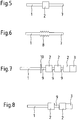
- Fig. 5 shows the cleaning device after cleaning the instrument channel 4.
- the detachable cleaning element 3 has detached due to the back movement of the cleaning device within the instrument channel from the support member 1.
- a protrusion of the support member 1 with a portion with a phase 7 distal from the fixed cleaning element 2 By detachment of the cleaning element 3, a protrusion of the support member 1 with a portion with a phase 7 distal from the fixed cleaning element 2, the spattering of cleaning liquid and the like after removal of the cleaning device from the instrument channel 4 reduced.
- FIG. 6 A particular embodiment of the attachment of a fixed cleaning element 2 is in Figure 6 shown.
- the support element 1 shows an area which is provided with a thread 8. On the thread 8 to be fixed cleaning element 2 is screwed from felt.
- the cleaning element 2 shows a bore whose diameter is slightly larger than the nominal diameter of the carrier element 1. A defined release of the fixed cleaning element 2 from the support element 1 is thereby made possible.
- the carrier element 1 can be recycled again after its application, for example by sterilization and, provided with new cleaning elements 2 and 3 to be used once again, can be used again for cleaning instrument channels 4.
- By recycling and reuse of the support member 1 costs can be significantly reduced.
- the distal end of the support element 1 is rounded in order to avoid damage to the instrument channel 4 and to allow a simpler insertion of the cleaning device into the instrument channel 4.
- FIG Fig. 7 Another particular arrangement of the fixed cleaning elements 2 on the rod-shaped support element 1 according to the invention is shown in FIG Fig. 7 shown.
- a space 9 is provided between the two fixed cleaning elements 2. This makes it possible for contaminants to be discharged to be collected therein and, after passage through the instrument channel 4, dropped out of the instrument channel 4 when the cleaning device exits or is removed manually. In this way, the impurities that accumulate in the space 9, not distributed during retraction of the cleaning device through the instrument channel 4 back into this.
- These gaps 9 also facilitate the introduction of the cleaning device, since the cleaning elements 2 and 3 are constructed of a compressible material and show a larger diameter than the instrument channel 4.
- the gap 9 therefore provides space according to the invention, in which the cleaning elements 2 and 3 spread by their change in shape upon entry into the instrument channel 4 and can adapt well in this way the channel shape.
- On the support element 1 a plurality of cleaning elements 2 are fixed, which consist of felt. They therefore have both abrasive and absorbing properties.
- the proximal fixated starslement 10 is constructed of an elastic plastic and is additionally provided with a scraper edge 10. This has the advantage that liquids that are not completely captured or absorbed by the cleaning elements 2 and 3 are stripped off the instrument channel 4.
- Fig. 7 shows an alternative exemplary embodiment of the cleaning device.
- the cleaning device in Fig. 7 shows several cleaning elements 2 and a detachable cleaning element 3 with different diameters.
- the diameters decrease from proximal to distal. This allows for a simpler insertion of the cleaning device in the instrument channel 4 and on the other hand by the varying compression of the cleaning elements 2 and 3 arise different degrees of hardness of the cleaning elements 2 and 3, which support the erosive, gathering and receiving functions of the cleaning device, resulting in a particularly effective cleaning results.
- FIG. 9 An alternative embodiment of the possibility of attachment of the cleaning element 3 on the carrier element and the separation after the exit from the instrument channel 4 shows Fig. 9 ,
- the cleaning element 3 is inhibited in its displaceability on the carrier element 1 by a stop 12 mounted proximally and distally on the carrier element 1.
- These stops 12 are formed in this embodiment of plastic rings, the are mounted non-slip proximally and distally of the cleaning element 3.
- the cleaning element 3 is separated after the distal exit from the instrument channel 4 with a cutting device at the intended separation point 11.
- This modular design of the cleaning device offers the user numerous opportunities to put together a cleaning device for individual use for cleaning medical instrument channels.
- Fig. 10 shows a cleaning device according to the invention.
- the support element 1 with cleaning elements 3, which has passed the distal end of the instrument channel 4, is inserted into the container interior of the container 13 for receiving contaminated cleaning elements 3.
- the container 13 is in particular made of polyethylene, by which a high stability of the container is ensured.
- the cleaning device is inserted with the instrument channel 4 of the endoscopic system in the opening 16 of the container.
- the opening 16 of the container is provided with a flap, which is folded away by the introduction of the cleaning device. If there is no disposal of cleaning elements 3, the flap at the opening 16 ensures that the container 13 is sealed aseptically and contamination on the cleaning personnel is prevented.
- a removable waste container 17 is provided which allows the accumulation of cleaning elements 3 more cleaning devices after detachment from the carrier element 1.
- a sensor in the container 13 signals by means of the sensor signal a LED lamp 14, the user the correct position of the cleaning device in the device for releasing 15, so that the separation takes place by a Abnicken the support member 1 in the device 15, resulting in the breakage of provided separation point 11 leads and the cleaning element 3 is detached from the carrier element 1 and falls into the waste container 17 of the container for receiving contaminated cleaning elements 13.
- cleaning elements 3 of different cleaning devices can be disposed of together with the waste container 17.
- Fig. 11 shows a further variant for the disposal of contaminated cleaning elements 3.
- the device for releasing 15 is inserted manually via a contaminated cleaning element 3, which protrudes distally from the endoscopic system. By squeezing the device 15 to release the cleaning element 3 is gripped and detached upon retraction of the carrier element 1. After the subsequent removal of the endoscopic system from the device 15, the device 15 closes germ-free. The release device 15 is discarded as a unit together with the captured contaminated cleaning element 3.
- the support element 1, is recycled after the release of the contaminated cleaning elements 3 and the removal from the instrument channel 4 and can be reused.
Landscapes
- Health & Medical Sciences (AREA)
- Engineering & Computer Science (AREA)
- Life Sciences & Earth Sciences (AREA)
- Surgery (AREA)
- Mechanical Engineering (AREA)
- Heart & Thoracic Surgery (AREA)
- Pathology (AREA)
- Biomedical Technology (AREA)
- Oral & Maxillofacial Surgery (AREA)
- Medical Informatics (AREA)
- Molecular Biology (AREA)
- Animal Behavior & Ethology (AREA)
- General Health & Medical Sciences (AREA)
- Public Health (AREA)
- Veterinary Medicine (AREA)
- Nuclear Medicine, Radiotherapy & Molecular Imaging (AREA)
- Cleaning In General (AREA)
Claims (13)
- Dispositif de nettoyage destiné au nettoyage des canaux des instruments médicaux avec un élément de support (1) en forme de tige et au moins un élément de nettoyage (2, 3), lequel est raccordé à l'élément de support (1), caractérisé en ce que l'élément de nettoyage (2, 3) peut être retiré de l'élément de support (1) et au moins un élément de nettoyage est fixé de manière stationnaire à l'élément de support (1) et au moins un élément de nettoyage supplémentaire peut être retiré de l'élément de support, selon lequel au moins un élément de nettoyage (3) amovible est disposé de manière distale au niveau de l'élément de support (1) et tout au moins un élément de nettoyage (2) fixé de manière stationnaire est disposé de manière proximale par rapport à celui-ci et caractérisé en ce que l'élément de nettoyage (3) amovible est mis en place de manière distale au niveau de l'élément de support (1) par l'intermédiaire d'une jonction coulissante et caractérisé en ce que l'élément de support (1) présente une butée (12), laquelle délimite la capacité de coulissement de l'élément de nettoyage (2, 3) sur l'élément de support (1).
- Dispositif de nettoyage selon la revendication 1, caractérisé en ce qu'une zone de séparation (11) est prévue de manière distale au niveau de l'élément de support (1), laquelle permet une séparation d'une partie de l'élément de support (1) avec au moins un élément de nettoyage (2, 3).
- Dispositif de nettoyage selon l'une des revendications susmentionnées, caractérisé en ce que la structure de l'au moins un élément de nettoyage (2, 3) est constituée à partir d'un matériau semblable à du feutre et qui, en particulier, peut être comprimé.
- Dispositif de nettoyage selon l'une des revendications précédentes, caractérisé en ce que le matériau de tout au moins un élément de nettoyage (2, 3) peut absorber et dispenser un liquide de nettoyage.
- Dispositif de nettoyage selon l'une des revendications précédentes, caractérisé en ce que le degré de dureté des éléments de nettoyage (2, 3) est variable le long de l'élément de support (1).
- Dispositif de nettoyage selon l'une des revendications précédentes, caractérisé en ce que la structure de tout au moins un élément de nettoyage (2, 3) est constituée à partir d'un plastique élastique, lequel est pourvu, en particulier, d'une arête de raclage.
- Dispositif de nettoyage selon les revendications précédentes, caractérisé en ce que l'élément de support (1) présente une phase (7) au niveau de l'une de ses extrémités ou de ses deux extrémités.
- Dispositif de nettoyage selon l'une des revendications précédentes, caractérisé en ce que le matériau de l'élément de support (1) est sélectionné de telle sorte qu'il est stable de forme et, en particulier, est revêtu d'un plastique à faible coefficient de friction, par exemple du polytétrafluoroéthylène (PTFE).
- Dispositif de nettoyage selon l'une des revendications précédentes, caractérisé par un réservoir (13) qui est destiné à la réception des éléments de nettoyage (3) contaminés et qui comprend une ouverture (16) pouvant être verrouillée, à travers laquelle le tout au moins un élément de nettoyage (3) du dispositif de nettoyage peut être inséré dans le compartiment intérieur du réservoir, selon lequel le réservoir (13) est pourvu, dans le compartiment intérieur du réservoir, d'un dispositif destiné à la séparation (15) de l'au moins un élément de nettoyage (3) avec l'élément de support (1).
- Procédé destiné au nettoyage de canaux d'instrument (4) des instruments médicaux avec un dispositif de nettoyage, selon lequel le procédé comprend les phases suivantes : le déplacement du dispositif de nettoyage dans la direction axiale, à l'intérieur du canal des instruments (4), jusqu'à un point extrême, selon lequel, après avoir atteint le point extrême, le dispositif de nettoyage est déplacé vers l'extérieur dans la direction axiale opposée, à l'intérieur du canal des instruments (4), et un élément de nettoyage (3) amovible est séparé de l'élément de support (1), puis n'est plus impliqué dans le processus de nettoyage du canal des instruments (4) qui vient d'être nettoyé.
- Procédé selon la revendication 10, caractérisé en ce que le dispositif de nettoyage est déplacé dans la direction axiale, à l'intérieur du canal des instruments (4), par l'extrémité du canal des instruments (4), selon lequel au moins un élément de nettoyage (3) est séparé de l'élément de support (1) de telle sorte que l'élément de nettoyage (3) n'est plus impliqué dans le processus de nettoyage du canal des instruments (4), quand le dispositif de nettoyage est retiré dans la direction axiale opposée.
- Procédé selon la revendication 11, caractérisé en ce que l'élément de nettoyage (3) amovible est décomprimé après sa sortie en dehors du canal des instruments (4) et n'est plus réintroduit dans le canal des instruments (4) lors du retrait et se trouve par conséquent séparé de l'élément de support (1).
- Procédé selon l'une des revendications 10 à 12, caractérisé en ce que le dispositif de nettoyage est déplacé par l'extrémité du canal des instruments (4) dans la direction axiale, à l'intérieur du canal des instruments (4), selon lequel au moins un élément de nettoyage (3) avec la section de l'élément de support (1) est séparé de l'élément de support en forme de tige, laquelle section est positionnée de manière distale par rapport à la zone de séparation (11), de telle sorte que l'élément de nettoyage (3) avec la section distale de l'élément de support n'est plus impliqué dans le processus de nettoyage quand le dispositif de nettoyage est retiré à travers le canal des instruments (4).
Applications Claiming Priority (2)
| Application Number | Priority Date | Filing Date | Title |
|---|---|---|---|
| DE102008064205 | 2008-12-22 | ||
| DE102009011204A DE102009011204A1 (de) | 2008-12-22 | 2009-03-04 | Vorrichtung zur Reinigung von Instrumentenkanälen |
Publications (2)
| Publication Number | Publication Date |
|---|---|
| EP2204242A1 EP2204242A1 (fr) | 2010-07-07 |
| EP2204242B1 true EP2204242B1 (fr) | 2018-02-07 |
Family
ID=42194247
Family Applications (1)
| Application Number | Title | Priority Date | Filing Date |
|---|---|---|---|
| EP09015711.6A Not-in-force EP2204242B1 (fr) | 2008-12-22 | 2009-12-18 | Dispositif de nettoyage de canaux d'instruments |
Country Status (3)
| Country | Link |
|---|---|
| US (1) | US8991408B2 (fr) |
| EP (1) | EP2204242B1 (fr) |
| DE (1) | DE102009011204A1 (fr) |
Families Citing this family (6)
| Publication number | Priority date | Publication date | Assignee | Title |
|---|---|---|---|---|
| WO2010093008A1 (fr) * | 2009-02-12 | 2010-08-19 | 株式会社パイオラックスメディカルデバイス | Dispositif de nettoyage de conduit d'endoscope |
| EP3136944B1 (fr) * | 2014-05-02 | 2020-03-25 | United States Endoscopy Group, Inc. | Dispositif de nettoyage pour un dispositif endoscopique |
| WO2019234749A1 (fr) * | 2018-06-06 | 2019-12-12 | The Medical Research Infrastructure And Health Services Fund Of The Tel Aviv Medical Center | Dispositif, système et procédé de nettoyage de tube endotrachéal |
| GB2584089B (en) | 2019-05-20 | 2021-11-10 | Thermo Fisher Scient Bremen Gmbh | Cleaning ion optic multipole devices |
| US10809160B1 (en) * | 2019-08-21 | 2020-10-20 | Bn Intellectual Properties, Inc. | Endotracheal tube sound |
| CN212972123U (zh) * | 2020-03-24 | 2021-04-16 | 南微医学科技股份有限公司 | 清洁刷 |
Citations (4)
| Publication number | Priority date | Publication date | Assignee | Title |
|---|---|---|---|---|
| DE20012968U1 (de) * | 2000-07-27 | 2001-02-08 | Stötter, Turid, 24619 Bornhöved | Zahnbürste |
| EP1348352A2 (fr) * | 2002-03-27 | 2003-10-01 | Geka Brush Gmbh | Unité applicateur de cosmétique |
| JP2006051057A (ja) * | 2004-08-09 | 2006-02-23 | Pentax Corp | 内視鏡用掃除ブラシ |
| JP2008284317A (ja) * | 2007-05-15 | 2008-11-27 | River Seiko:Kk | 内視鏡の管路内掃除ブラシ |
Family Cites Families (9)
| Publication number | Priority date | Publication date | Assignee | Title |
|---|---|---|---|---|
| US3205518A (en) * | 1963-06-05 | 1965-09-14 | John W Romaine | Cleaning device |
| US5964004A (en) * | 1996-09-24 | 1999-10-12 | Bean; Douglas Colin | Device for cleaning medical endoscopic tubes |
| AUPP537098A0 (en) * | 1998-08-20 | 1998-09-10 | Novapharm Research (Australia) Pty Ltd | Endoscope cleaning device |
| US7114629B2 (en) * | 2001-04-30 | 2006-10-03 | Tyco Healthcare Group Lp | Medical waste disposal system |
| JP2006187556A (ja) * | 2005-01-07 | 2006-07-20 | Pentax Corp | 内視鏡用掃除ブラシ |
| JP2008540026A (ja) * | 2005-05-17 | 2008-11-20 | タック,フランシス ホートン | 内視鏡用の引き通し用具 |
| JP4951259B2 (ja) * | 2006-03-29 | 2012-06-13 | オリンパスメディカルシステムズ株式会社 | 内視鏡管路洗滌ブラシカセット |
| DE102006022366B3 (de) * | 2006-05-12 | 2008-01-03 | Siemens Audiologische Technik Gmbh | Reinigungswerkzeug für einen Hörschlauch |
| DE202007000793U1 (de) | 2007-01-18 | 2008-05-21 | Maslanka, Herbert | Reinigungsdocht für einen Instrumentenkanal eines medizinischen Instruments |
-
2009
- 2009-03-04 DE DE102009011204A patent/DE102009011204A1/de not_active Withdrawn
- 2009-12-18 EP EP09015711.6A patent/EP2204242B1/fr not_active Not-in-force
- 2009-12-21 US US12/643,776 patent/US8991408B2/en active Active
Patent Citations (4)
| Publication number | Priority date | Publication date | Assignee | Title |
|---|---|---|---|---|
| DE20012968U1 (de) * | 2000-07-27 | 2001-02-08 | Stötter, Turid, 24619 Bornhöved | Zahnbürste |
| EP1348352A2 (fr) * | 2002-03-27 | 2003-10-01 | Geka Brush Gmbh | Unité applicateur de cosmétique |
| JP2006051057A (ja) * | 2004-08-09 | 2006-02-23 | Pentax Corp | 内視鏡用掃除ブラシ |
| JP2008284317A (ja) * | 2007-05-15 | 2008-11-27 | River Seiko:Kk | 内視鏡の管路内掃除ブラシ |
Also Published As
| Publication number | Publication date |
|---|---|
| DE102009011204A1 (de) | 2010-06-24 |
| EP2204242A1 (fr) | 2010-07-07 |
| US8991408B2 (en) | 2015-03-31 |
| US20100163074A1 (en) | 2010-07-01 |
Similar Documents
| Publication | Publication Date | Title |
|---|---|---|
| DE69110691T2 (de) | Endoskop mit Schutzhülle. | |
| DE3878272T2 (de) | Festteilchenfilter fuer ein medizinisches absauggeraet. | |
| EP2204242A1 (fr) | Dispositif de nettoyage de canaux d'instruments | |
| DE4305226C2 (de) | Vorrichtung für Nadeln für transkutane Biopsien | |
| EP0402885B1 (fr) | Canal de sonde flexible | |
| DE3542667C2 (fr) | ||
| EP1970016B1 (fr) | Dispositif de fixation d'un fil chirurgical sur un os | |
| DE102011120004B3 (de) | Vorrichtung zum Ablösen wandständiger Thromben aus einem Körpergefäß | |
| DE2800362B2 (de) | Endoskop mit steuerbar beweglicher Führungsröhre für ein Instrument | |
| DE2804058A1 (de) | Medizinisches geraet zur entfernung von fremdkoerpern aus einem koerperhohlraum | |
| DE3506464A1 (de) | Endoskopoptik zur durchfuehrung durch trokarhuelsen oder dergleichen | |
| EP2296554A1 (fr) | Dispositif destiné à recueillir du sang | |
| DE102008005940A1 (de) | Abrasionsvorrichtung | |
| DE102014117430B3 (de) | Design für eine vereinfachte Entfernung eines Ballon Applikators | |
| EP4321184A1 (fr) | Ensemble de lavage | |
| DE3206846C2 (de) | Mechanischer Lithotriptor | |
| WO2019162303A1 (fr) | Dispositif et procédé pour nettoyer un canal auditif externe | |
| EP4046671B1 (fr) | Agencement de rinçage | |
| DE3340581C1 (de) | Mechanischer Lithotriptor | |
| EP1203565A1 (fr) | Dispositif de biopsie endoscopique, notamment pour cartilage | |
| DE3545176C2 (fr) | ||
| EP4559400A1 (fr) | Unité de nettoyage pour nettoyer une enceinte entourant une zone de réception de patient | |
| DE3511448C2 (de) | Harnleiterkatheter | |
| DE2745015A1 (de) | Fluessigkeiten aufsaugende absorptionsvorrichtung zur verwendung mit endoskopen | |
| DE9420422U1 (de) | Chirurgisches Instrument |
Legal Events
| Date | Code | Title | Description |
|---|---|---|---|
| PUAI | Public reference made under article 153(3) epc to a published international application that has entered the european phase |
Free format text: ORIGINAL CODE: 0009012 |
|
| AK | Designated contracting states |
Kind code of ref document: A1 Designated state(s): AT BE BG CH CY CZ DE DK EE ES FI FR GB GR HR HU IE IS IT LI LT LU LV MC MK MT NL NO PL PT RO SE SI SK SM TR |
|
| AX | Request for extension of the european patent |
Extension state: AL BA RS |
|
| RIN1 | Information on inventor provided before grant (corrected) |
Inventor name: HANSEN, NORBERT, DR. |
|
| 17P | Request for examination filed |
Effective date: 20101021 |
|
| RIC1 | Information provided on ipc code assigned before grant |
Ipc: A61B 19/00 20060101ALI20110117BHEP Ipc: B08B 9/043 20060101AFI20110117BHEP |
|
| 17Q | First examination report despatched |
Effective date: 20110203 |
|
| GRAP | Despatch of communication of intention to grant a patent |
Free format text: ORIGINAL CODE: EPIDOSNIGR1 |
|
| RIC1 | Information provided on ipc code assigned before grant |
Ipc: A61B 90/70 20160101ALN20170222BHEP Ipc: B08B 9/043 20060101AFI20170222BHEP |
|
| INTG | Intention to grant announced |
Effective date: 20170310 |
|
| GRAS | Grant fee paid |
Free format text: ORIGINAL CODE: EPIDOSNIGR3 |
|
| GRAJ | Information related to disapproval of communication of intention to grant by the applicant or resumption of examination proceedings by the epo deleted |
Free format text: ORIGINAL CODE: EPIDOSDIGR1 |
|
| GRAL | Information related to payment of fee for publishing/printing deleted |
Free format text: ORIGINAL CODE: EPIDOSDIGR3 |
|
| GRAP | Despatch of communication of intention to grant a patent |
Free format text: ORIGINAL CODE: EPIDOSNIGR1 |
|
| INTC | Intention to grant announced (deleted) | ||
| RIC1 | Information provided on ipc code assigned before grant |
Ipc: B08B 9/043 20060101AFI20170628BHEP Ipc: A61B 90/70 20160101ALN20170628BHEP |
|
| INTG | Intention to grant announced |
Effective date: 20170724 |
|
| GRAA | (expected) grant |
Free format text: ORIGINAL CODE: 0009210 |
|
| RAP1 | Party data changed (applicant data changed or rights of an application transferred) |
Owner name: KARL STORZ SE & CO. KG |
|
| AK | Designated contracting states |
Kind code of ref document: B1 Designated state(s): AT BE BG CH CY CZ DE DK EE ES FI FR GB GR HR HU IE IS IT LI LT LU LV MC MK MT NL NO PL PT RO SE SI SK SM TR |
|
| REG | Reference to a national code |
Ref country code: GB Ref legal event code: FG4D Free format text: NOT ENGLISH |
|
| REG | Reference to a national code |
Ref country code: AT Ref legal event code: REF Ref document number: 968560 Country of ref document: AT Kind code of ref document: T Effective date: 20180215 Ref country code: CH Ref legal event code: EP |
|
| REG | Reference to a national code |
Ref country code: IE Ref legal event code: FG4D Free format text: LANGUAGE OF EP DOCUMENT: GERMAN |
|
| REG | Reference to a national code |
Ref country code: DE Ref legal event code: R096 Ref document number: 502009014717 Country of ref document: DE |
|
| REG | Reference to a national code |
Ref country code: NL Ref legal event code: MP Effective date: 20180207 |
|
| PG25 | Lapsed in a contracting state [announced via postgrant information from national office to epo] |
Ref country code: HR Free format text: LAPSE BECAUSE OF FAILURE TO SUBMIT A TRANSLATION OF THE DESCRIPTION OR TO PAY THE FEE WITHIN THE PRESCRIBED TIME-LIMIT Effective date: 20180207 Ref country code: CY Free format text: LAPSE BECAUSE OF FAILURE TO SUBMIT A TRANSLATION OF THE DESCRIPTION OR TO PAY THE FEE WITHIN THE PRESCRIBED TIME-LIMIT Effective date: 20180207 Ref country code: LT Free format text: LAPSE BECAUSE OF FAILURE TO SUBMIT A TRANSLATION OF THE DESCRIPTION OR TO PAY THE FEE WITHIN THE PRESCRIBED TIME-LIMIT Effective date: 20180207 Ref country code: NL Free format text: LAPSE BECAUSE OF FAILURE TO SUBMIT A TRANSLATION OF THE DESCRIPTION OR TO PAY THE FEE WITHIN THE PRESCRIBED TIME-LIMIT Effective date: 20180207 Ref country code: ES Free format text: LAPSE BECAUSE OF FAILURE TO SUBMIT A TRANSLATION OF THE DESCRIPTION OR TO PAY THE FEE WITHIN THE PRESCRIBED TIME-LIMIT Effective date: 20180207 Ref country code: NO Free format text: LAPSE BECAUSE OF FAILURE TO SUBMIT A TRANSLATION OF THE DESCRIPTION OR TO PAY THE FEE WITHIN THE PRESCRIBED TIME-LIMIT Effective date: 20180507 Ref country code: FI Free format text: LAPSE BECAUSE OF FAILURE TO SUBMIT A TRANSLATION OF THE DESCRIPTION OR TO PAY THE FEE WITHIN THE PRESCRIBED TIME-LIMIT Effective date: 20180207 |
|
| PG25 | Lapsed in a contracting state [announced via postgrant information from national office to epo] |
Ref country code: SE Free format text: LAPSE BECAUSE OF FAILURE TO SUBMIT A TRANSLATION OF THE DESCRIPTION OR TO PAY THE FEE WITHIN THE PRESCRIBED TIME-LIMIT Effective date: 20180207 Ref country code: LV Free format text: LAPSE BECAUSE OF FAILURE TO SUBMIT A TRANSLATION OF THE DESCRIPTION OR TO PAY THE FEE WITHIN THE PRESCRIBED TIME-LIMIT Effective date: 20180207 Ref country code: PL Free format text: LAPSE BECAUSE OF FAILURE TO SUBMIT A TRANSLATION OF THE DESCRIPTION OR TO PAY THE FEE WITHIN THE PRESCRIBED TIME-LIMIT Effective date: 20180207 Ref country code: GR Free format text: LAPSE BECAUSE OF FAILURE TO SUBMIT A TRANSLATION OF THE DESCRIPTION OR TO PAY THE FEE WITHIN THE PRESCRIBED TIME-LIMIT Effective date: 20180508 Ref country code: IS Free format text: LAPSE BECAUSE OF FAILURE TO SUBMIT A TRANSLATION OF THE DESCRIPTION OR TO PAY THE FEE WITHIN THE PRESCRIBED TIME-LIMIT Effective date: 20180607 Ref country code: BG Free format text: LAPSE BECAUSE OF FAILURE TO SUBMIT A TRANSLATION OF THE DESCRIPTION OR TO PAY THE FEE WITHIN THE PRESCRIBED TIME-LIMIT Effective date: 20180507 |
|
| PG25 | Lapsed in a contracting state [announced via postgrant information from national office to epo] |
Ref country code: MT Free format text: LAPSE BECAUSE OF FAILURE TO SUBMIT A TRANSLATION OF THE DESCRIPTION OR TO PAY THE FEE WITHIN THE PRESCRIBED TIME-LIMIT Effective date: 20180207 |
|
| PG25 | Lapsed in a contracting state [announced via postgrant information from national office to epo] |
Ref country code: IT Free format text: LAPSE BECAUSE OF FAILURE TO SUBMIT A TRANSLATION OF THE DESCRIPTION OR TO PAY THE FEE WITHIN THE PRESCRIBED TIME-LIMIT Effective date: 20180207 Ref country code: EE Free format text: LAPSE BECAUSE OF FAILURE TO SUBMIT A TRANSLATION OF THE DESCRIPTION OR TO PAY THE FEE WITHIN THE PRESCRIBED TIME-LIMIT Effective date: 20180207 Ref country code: RO Free format text: LAPSE BECAUSE OF FAILURE TO SUBMIT A TRANSLATION OF THE DESCRIPTION OR TO PAY THE FEE WITHIN THE PRESCRIBED TIME-LIMIT Effective date: 20180207 |
|
| REG | Reference to a national code |
Ref country code: DE Ref legal event code: R097 Ref document number: 502009014717 Country of ref document: DE |
|
| PG25 | Lapsed in a contracting state [announced via postgrant information from national office to epo] |
Ref country code: SK Free format text: LAPSE BECAUSE OF FAILURE TO SUBMIT A TRANSLATION OF THE DESCRIPTION OR TO PAY THE FEE WITHIN THE PRESCRIBED TIME-LIMIT Effective date: 20180207 Ref country code: SM Free format text: LAPSE BECAUSE OF FAILURE TO SUBMIT A TRANSLATION OF THE DESCRIPTION OR TO PAY THE FEE WITHIN THE PRESCRIBED TIME-LIMIT Effective date: 20180207 Ref country code: CZ Free format text: LAPSE BECAUSE OF FAILURE TO SUBMIT A TRANSLATION OF THE DESCRIPTION OR TO PAY THE FEE WITHIN THE PRESCRIBED TIME-LIMIT Effective date: 20180207 Ref country code: DK Free format text: LAPSE BECAUSE OF FAILURE TO SUBMIT A TRANSLATION OF THE DESCRIPTION OR TO PAY THE FEE WITHIN THE PRESCRIBED TIME-LIMIT Effective date: 20180207 |
|
| PLBE | No opposition filed within time limit |
Free format text: ORIGINAL CODE: 0009261 |
|
| REG | Reference to a national code |
Ref country code: CH Ref legal event code: PK Free format text: BERICHTIGUNGEN |
|
| STAA | Information on the status of an ep patent application or granted ep patent |
Free format text: STATUS: NO OPPOSITION FILED WITHIN TIME LIMIT |
|
| RIC2 | Information provided on ipc code assigned after grant |
Ipc: B08B 9/043 20060101AFI20170628BHEP Ipc: A61B 90/70 20160101ALN20170628BHEP |
|
| 26N | No opposition filed |
Effective date: 20181108 |
|
| REG | Reference to a national code |
Ref country code: CH Ref legal event code: PK Free format text: BERICHTIGUNGEN |
|
| RIC2 | Information provided on ipc code assigned after grant |
Ipc: B08B 9/043 20060101AFI20170628BHEP Ipc: A61B 90/70 20160101ALN20170628BHEP |
|
| PG25 | Lapsed in a contracting state [announced via postgrant information from national office to epo] |
Ref country code: SI Free format text: LAPSE BECAUSE OF FAILURE TO SUBMIT A TRANSLATION OF THE DESCRIPTION OR TO PAY THE FEE WITHIN THE PRESCRIBED TIME-LIMIT Effective date: 20180207 |
|
| REG | Reference to a national code |
Ref country code: CH Ref legal event code: PL |
|
| PG25 | Lapsed in a contracting state [announced via postgrant information from national office to epo] |
Ref country code: MC Free format text: LAPSE BECAUSE OF FAILURE TO SUBMIT A TRANSLATION OF THE DESCRIPTION OR TO PAY THE FEE WITHIN THE PRESCRIBED TIME-LIMIT Effective date: 20180207 Ref country code: LU Free format text: LAPSE BECAUSE OF NON-PAYMENT OF DUE FEES Effective date: 20181218 |
|
| REG | Reference to a national code |
Ref country code: IE Ref legal event code: MM4A |
|
| REG | Reference to a national code |
Ref country code: BE Ref legal event code: MM Effective date: 20181231 |
|
| PG25 | Lapsed in a contracting state [announced via postgrant information from national office to epo] |
Ref country code: IE Free format text: LAPSE BECAUSE OF NON-PAYMENT OF DUE FEES Effective date: 20181218 |
|
| PG25 | Lapsed in a contracting state [announced via postgrant information from national office to epo] |
Ref country code: BE Free format text: LAPSE BECAUSE OF NON-PAYMENT OF DUE FEES Effective date: 20181231 |
|
| PG25 | Lapsed in a contracting state [announced via postgrant information from national office to epo] |
Ref country code: LI Free format text: LAPSE BECAUSE OF NON-PAYMENT OF DUE FEES Effective date: 20181231 Ref country code: CH Free format text: LAPSE BECAUSE OF NON-PAYMENT OF DUE FEES Effective date: 20181231 |
|
| REG | Reference to a national code |
Ref country code: AT Ref legal event code: MM01 Ref document number: 968560 Country of ref document: AT Kind code of ref document: T Effective date: 20181218 |
|
| PG25 | Lapsed in a contracting state [announced via postgrant information from national office to epo] |
Ref country code: TR Free format text: LAPSE BECAUSE OF FAILURE TO SUBMIT A TRANSLATION OF THE DESCRIPTION OR TO PAY THE FEE WITHIN THE PRESCRIBED TIME-LIMIT Effective date: 20180207 |
|
| PG25 | Lapsed in a contracting state [announced via postgrant information from national office to epo] |
Ref country code: AT Free format text: LAPSE BECAUSE OF NON-PAYMENT OF DUE FEES Effective date: 20181218 |
|
| PG25 | Lapsed in a contracting state [announced via postgrant information from national office to epo] |
Ref country code: PT Free format text: LAPSE BECAUSE OF FAILURE TO SUBMIT A TRANSLATION OF THE DESCRIPTION OR TO PAY THE FEE WITHIN THE PRESCRIBED TIME-LIMIT Effective date: 20180207 |
|
| PG25 | Lapsed in a contracting state [announced via postgrant information from national office to epo] |
Ref country code: MK Free format text: LAPSE BECAUSE OF NON-PAYMENT OF DUE FEES Effective date: 20180207 Ref country code: HU Free format text: LAPSE BECAUSE OF FAILURE TO SUBMIT A TRANSLATION OF THE DESCRIPTION OR TO PAY THE FEE WITHIN THE PRESCRIBED TIME-LIMIT; INVALID AB INITIO Effective date: 20091218 |
|
| PGFP | Annual fee paid to national office [announced via postgrant information from national office to epo] |
Ref country code: GB Payment date: 20211118 Year of fee payment: 13 Ref country code: FR Payment date: 20211117 Year of fee payment: 13 |
|
| PGFP | Annual fee paid to national office [announced via postgrant information from national office to epo] |
Ref country code: DE Payment date: 20220616 Year of fee payment: 14 |
|
| P01 | Opt-out of the competence of the unified patent court (upc) registered |
Effective date: 20230527 |
|
| GBPC | Gb: european patent ceased through non-payment of renewal fee |
Effective date: 20221218 |
|
| PG25 | Lapsed in a contracting state [announced via postgrant information from national office to epo] |
Ref country code: GB Free format text: LAPSE BECAUSE OF NON-PAYMENT OF DUE FEES Effective date: 20221218 |
|
| PG25 | Lapsed in a contracting state [announced via postgrant information from national office to epo] |
Ref country code: FR Free format text: LAPSE BECAUSE OF NON-PAYMENT OF DUE FEES Effective date: 20221231 |
|
| REG | Reference to a national code |
Ref country code: DE Ref legal event code: R119 Ref document number: 502009014717 Country of ref document: DE |
|
| PG25 | Lapsed in a contracting state [announced via postgrant information from national office to epo] |
Ref country code: DE Free format text: LAPSE BECAUSE OF NON-PAYMENT OF DUE FEES Effective date: 20240702 |
|
| PG25 | Lapsed in a contracting state [announced via postgrant information from national office to epo] |
Ref country code: DE Free format text: LAPSE BECAUSE OF NON-PAYMENT OF DUE FEES Effective date: 20240702 |