EP2204263A1 - Dispositif de traitement - Google Patents
Dispositif de traitement Download PDFInfo
- Publication number
- EP2204263A1 EP2204263A1 EP08022574A EP08022574A EP2204263A1 EP 2204263 A1 EP2204263 A1 EP 2204263A1 EP 08022574 A EP08022574 A EP 08022574A EP 08022574 A EP08022574 A EP 08022574A EP 2204263 A1 EP2204263 A1 EP 2204263A1
- Authority
- EP
- European Patent Office
- Prior art keywords
- suction
- workpiece
- contour
- machining
- region
- Prior art date
- Legal status (The legal status is an assumption and is not a legal conclusion. Google has not performed a legal analysis and makes no representation as to the accuracy of the status listed.)
- Granted
Links
- 238000001514 detection method Methods 0.000 claims abstract description 28
- 238000000034 method Methods 0.000 claims abstract description 11
- 230000003287 optical effect Effects 0.000 claims abstract description 3
- 238000003754 machining Methods 0.000 claims description 19
- 239000002245 particle Substances 0.000 claims description 7
- 239000002023 wood Substances 0.000 claims description 4
- 238000003672 processing method Methods 0.000 claims 2
- 239000000463 material Substances 0.000 claims 1
- 239000002184 metal Substances 0.000 claims 1
- 239000004033 plastic Substances 0.000 claims 1
- 239000000428 dust Substances 0.000 description 4
- 238000007664 blowing Methods 0.000 description 3
- 230000007613 environmental effect Effects 0.000 description 2
- 208000027418 Wounds and injury Diseases 0.000 description 1
- 230000004913 activation Effects 0.000 description 1
- 230000001680 brushing effect Effects 0.000 description 1
- 238000004140 cleaning Methods 0.000 description 1
- 230000006378 damage Effects 0.000 description 1
- 230000001419 dependent effect Effects 0.000 description 1
- 208000014674 injury Diseases 0.000 description 1
Images


Classifications
-
- B—PERFORMING OPERATIONS; TRANSPORTING
- B24—GRINDING; POLISHING
- B24B—MACHINES, DEVICES, OR PROCESSES FOR GRINDING OR POLISHING; DRESSING OR CONDITIONING OF ABRADING SURFACES; FEEDING OF GRINDING, POLISHING, OR LAPPING AGENTS
- B24B55/00—Safety devices for grinding or polishing machines; Accessories fitted to grinding or polishing machines for keeping tools or parts of the machine in good working condition
- B24B55/06—Dust extraction equipment on grinding or polishing machines
-
- B—PERFORMING OPERATIONS; TRANSPORTING
- B24—GRINDING; POLISHING
- B24B—MACHINES, DEVICES, OR PROCESSES FOR GRINDING OR POLISHING; DRESSING OR CONDITIONING OF ABRADING SURFACES; FEEDING OF GRINDING, POLISHING, OR LAPPING AGENTS
- B24B55/00—Safety devices for grinding or polishing machines; Accessories fitted to grinding or polishing machines for keeping tools or parts of the machine in good working condition
- B24B55/06—Dust extraction equipment on grinding or polishing machines
- B24B55/08—Dust extraction equipment on grinding or polishing machines specially designed for belt grinding machines
Definitions
- the present invention relates to a processing device for processing plate-shaped workpieces, comprising a processing unit for processing workpieces, a conveying device for transporting the workpieces to be processed, and a suction device for sucking off particles resulting from processing.
- An apparatus for removing sanding dust on workpieces in grinding machines is known, which is suitable for removing sanding dust from workpieces in grinding machines, in particular in wide-belt sanding machines.
- a compressed air supply is formed with an outlet opening arranged in or opposite the workpiece transport direction of the grinding zone. The thereby blown off grinding dust is sucked in with a suction device.
- a plurality of controllable blowing devices are formed in this device, which are switched depending on the size of the workpiece to be blasted off.
- the invention has for its object to provide a processing device for the processing of plate-shaped workpieces, which allows an energy-efficient and noise-reduced operation.
- the invention is based on the idea to make the operation of the suction device by an optimized use of the suction device more energy efficient.
- the processing device according to the invention has a suction region of a suction device with an adjustable contour.
- a suction opening with a variable, that is adjustable contour, it is particularly advantageous to change the geometry of the suction opening, thereby it is not constantly necessary to use the entire width z.
- This extracted air mass must be produced under high energy use.
- the device according to the invention allows energy-optimized and needs-based suck. It should be noted that in heated or cooled rooms, the extracted air volume must be supplied from the outside again and this is also to heat or cool again. Further reduces the noise level caused by the processing unit, since less air mass is sucked.
- the workpiece detection device is designed to start a suction operation of the suction device as soon as a workpiece is in a processing region and / or to end the suction operation of the suction device as soon as no workpiece is in the processing region. This makes it particularly advantageous possible to let the suction only take place when it is really needed. In this way, it is particularly advantageous possible to save energy.
- a suction channel segmented in its suction channel is formed with individually controllable segment locking elements, wherein the contour of the suction region is variably adjustable.
- a suction channel segmented in its suction with individually controllable segment locking elements depending on the contour of the workpiece in the region of the workpiece opens the segment locking elements and thus able to suck in about this area. This makes it particularly advantageous possible to suck only in the area in which to be sucked and thus save energy.
- a blower while the suction device is switched on, a blower is switched on.
- the blower has several selectively switchable and turn-off nozzles.
- the blower is formed approximately in the region of the suction device. In this way, it is possible to blow off adhering particles on the workpieces by means of the blower and then suck in by means of the suction device.
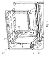
- FIG. 1 and 2 show a processing device 12, in particular a wide-belt sanding machine, which has a processing device 12.
- the processing device 12 has in the embodiment shown two suction devices 16 and a processing unit 30 with a grinding belt 13, wherein a suction device 16 is arranged in the conveying direction of the workpiece 15 in front of the grinding belt 13 and the other suction device 16 behind the grinding belt 13.
- the suction devices 16 each have a suction opening 18, which extends over the entire suction area, in particular at least over the width of the conveying device 14 extending below the suction direction.
- Suction ports 17 are formed on the suction device 16. By means of these suction connections 17, a negative pressure is generated in the interior of the suction device 16, as a result of which it is possible to suck off air having particles through the suction region 18.
- a workpiece 15 is conveyed via the conveyor 14 (not shown) along the in Fig. 1 and 2 shown arrow moves in the direction of the processing device 12.
- a workpiece detection device 20 recognizes the workpiece 15, it detects the contour, that is to say the geometric dimensions, of the workpiece and transmits these dimensions to the processing device 12.
- the processing device 12 then adjusts the width of the suction region 18, depending on the dimensions of the workpiece 15. As soon as the workpiece detection device 20 detects that the workpiece 15 is in the suction region, the suction process is started. At the same time, the workpiece may be processed by the processing unit 30. As soon as the workpiece detection device 20 detects that the workpiece 15 has left or left the suction region, the suction device 16 is stopped.
- this information z. B. be known throughout the processing in the processing apparatus 12 or in a processing line.
- the processing device not as part of a processing unit 30 with a Execute abrasive belt 30, ie there must be no abrasive belt 13 is formed, which surrounds the processing device 12.
- the processing device 12 may be formed wherever there is a need for a cleaning of a workpiece or similar, in particular plate-shaped, objects.
- Fig. 3 shows two possible embodiments of a processing device 12. It shows in the Fig. 3 Illustrated in the foreground embodiment of a processing device 12, a suction device 16 which has a segmented in its suction suction channel 22.
- the suction device 16 has a suction connection 17, as well as three suction channels 22 which extend therefrom and extend to the suction region 18.
- the segment locking elements 24 can be controlled individually. In the embodiment shown, three segment locking elements 24 are shown, it is also possible to form two segment locking elements 24 and a plurality of segment locking elements 24. From the suction connection 17, a connecting piece leads to a central suction device.
- the back in Fig. 3 shown embodiment of a suction device 16 differs from the first embodiment in that no segment locking elements are formed, but separate individual suction channels 22, which each have their own suction port 17.
- the suction ports 17 are each switched on and off individually via a valve, thereby the width of the suction region or the contour of the suction region 18 can be set variably.
- three suction channels 22 are shown, it However, it is also possible only two or a plurality of suction channels 22 form, which are each provided with its own suction port. The more suction channels 22 are formed, the more accurate the contour of the suction region 18 can be adjusted.
Landscapes
- Engineering & Computer Science (AREA)
- Mechanical Engineering (AREA)
- Constituent Portions Of Griding Lathes, Driving, Sensing And Control (AREA)
- Cleaning In General (AREA)
Priority Applications (4)
| Application Number | Priority Date | Filing Date | Title |
|---|---|---|---|
| DE502008002584T DE502008002584D1 (de) | 2008-12-30 | 2008-12-30 | Bearbeitungsvorrichtung |
| PL08022574T PL2204263T3 (pl) | 2008-12-30 | 2008-12-30 | Urządzenie obróbkowe |
| EP08022574A EP2204263B1 (fr) | 2008-12-30 | 2008-12-30 | Dispositif de traitement |
| ES08022574T ES2360379T3 (es) | 2008-12-30 | 2008-12-30 | Dispositivo de mecanizado. |
Applications Claiming Priority (1)
| Application Number | Priority Date | Filing Date | Title |
|---|---|---|---|
| EP08022574A EP2204263B1 (fr) | 2008-12-30 | 2008-12-30 | Dispositif de traitement |
Publications (2)
| Publication Number | Publication Date |
|---|---|
| EP2204263A1 true EP2204263A1 (fr) | 2010-07-07 |
| EP2204263B1 EP2204263B1 (fr) | 2011-02-09 |
Family
ID=40673600
Family Applications (1)
| Application Number | Title | Priority Date | Filing Date |
|---|---|---|---|
| EP08022574A Not-in-force EP2204263B1 (fr) | 2008-12-30 | 2008-12-30 | Dispositif de traitement |
Country Status (4)
| Country | Link |
|---|---|
| EP (1) | EP2204263B1 (fr) |
| DE (1) | DE502008002584D1 (fr) |
| ES (1) | ES2360379T3 (fr) |
| PL (1) | PL2204263T3 (fr) |
Citations (4)
| Publication number | Priority date | Publication date | Assignee | Title |
|---|---|---|---|---|
| US2324019A (en) * | 1942-05-18 | 1943-07-13 | American Air Filter Co | Work cabinet |
| GB806341A (en) * | 1954-03-13 | 1958-12-23 | Arthur Calderbank | Improvements in or relating to dust-laden air extraction systems |
| DE4232830C1 (de) | 1992-09-30 | 1993-10-21 | Georg Weber | Vorrichtung zum Entfernen von Schleifstaub von Werkstücken in Schleifmaschinen |
| CN201105417Y (zh) * | 2007-10-18 | 2008-08-27 | 武汉理想新世纪工贸发展有限公司 | 风向和风量可调式打磨吸尘装置 |
-
2008
- 2008-12-30 ES ES08022574T patent/ES2360379T3/es active Active
- 2008-12-30 DE DE502008002584T patent/DE502008002584D1/de active Active
- 2008-12-30 EP EP08022574A patent/EP2204263B1/fr not_active Not-in-force
- 2008-12-30 PL PL08022574T patent/PL2204263T3/pl unknown
Patent Citations (4)
| Publication number | Priority date | Publication date | Assignee | Title |
|---|---|---|---|---|
| US2324019A (en) * | 1942-05-18 | 1943-07-13 | American Air Filter Co | Work cabinet |
| GB806341A (en) * | 1954-03-13 | 1958-12-23 | Arthur Calderbank | Improvements in or relating to dust-laden air extraction systems |
| DE4232830C1 (de) | 1992-09-30 | 1993-10-21 | Georg Weber | Vorrichtung zum Entfernen von Schleifstaub von Werkstücken in Schleifmaschinen |
| CN201105417Y (zh) * | 2007-10-18 | 2008-08-27 | 武汉理想新世纪工贸发展有限公司 | 风向和风量可调式打磨吸尘装置 |
Also Published As
| Publication number | Publication date |
|---|---|
| PL2204263T3 (pl) | 2011-07-29 |
| EP2204263B1 (fr) | 2011-02-09 |
| ES2360379T3 (es) | 2011-06-03 |
| DE502008002584D1 (de) | 2011-03-24 |
Similar Documents
| Publication | Publication Date | Title |
|---|---|---|
| DE19651662C2 (de) | Vorrichtung zum Absaugen von Bearbeitungsrückständen aus einem Bearbeitungsbereich einer Bearbeitungsmaschine | |
| EP3307472B1 (fr) | Dispositif de coupe de flans de tôle dans une bande de tôle | |
| EP1344604B1 (fr) | Procédé et dispositif pour chanfreiner des découpes de verre | |
| EP3349939B1 (fr) | Dispositif de coupe de flans de tôle dans une bande de tôle | |
| EP2476512B1 (fr) | Dispositif de soufflage pour bandes | |
| EP0217834A1 (fr) | Appareil de nettoyage de surfaces. | |
| EP3047940A1 (fr) | Dispositif d'aspiration de poussiere d'abrasion sur des ponceuses rotatives | |
| WO2002091842A1 (fr) | Dispositif permettant d'ecorcher et de depouiller un produit a traiter | |
| DE202014104833U1 (de) | Vorrichtung zum Ausblasen eines umlaufenden Schleifbands einer Bandschleifmaschine | |
| DE19756503B4 (de) | Kehlmaschine | |
| WO2008151814A1 (fr) | Dispositif et procédé pour nettoyer un élément en forme de bande en mouvement | |
| EP2204263B1 (fr) | Dispositif de traitement | |
| WO2019025542A1 (fr) | Dispositif d'aspiration à aspiration de poussière optimisée | |
| DE102005040420B4 (de) | Abrasionsvorrichtung | |
| DE4232830C5 (de) | Vorrichtung zum Entfernen von Schleifstaub von Werkstücken in Bandschleifmaschinen | |
| EP1509342B1 (fr) | Dispositif de nettoyage a sec de pieces | |
| DE102008052564A1 (de) | Durchlaufschleifmaschine zur Metallbearbeitung | |
| EP2433747B1 (fr) | Procédé et dispositif de ponçage des arêtes de plaques en verre s'étendant parallèlement les unes par rapport aux autres | |
| AT524760B1 (de) | Vorrichtung zum Bearbeiten von Platten mit einem Schleifkopf | |
| CH674331A5 (en) | Belt type grinding machine - has two endless belts with abrasive surfaces which pass around guide rollers and pressed against workpiece by shoes | |
| DE102005043548A1 (de) | Schleifring für ein Schleifrad | |
| EP1080798A2 (fr) | Dispositif pour enlever des résidus de résine d'une plaque métallique de pression | |
| DE820783C (de) | Verfahren und Maschine zum Entstauben von Werkstuecken, z. B. gegerbten Haeuten und Fellen | |
| DE102016014268A1 (de) | Vorrichtung und Verfahren zum Trennen von Pressgutmatten | |
| DE1047983B (de) | Saugrohr zur Spaeneabsaugung an Lederschaerfmaschinen mit Glockenmesser |
Legal Events
| Date | Code | Title | Description |
|---|---|---|---|
| PUAI | Public reference made under article 153(3) epc to a published international application that has entered the european phase |
Free format text: ORIGINAL CODE: 0009012 |
|
| 17P | Request for examination filed |
Effective date: 20090824 |
|
| AK | Designated contracting states |
Kind code of ref document: A1 Designated state(s): AT BE BG CH CY CZ DE DK EE ES FI FR GB GR HR HU IE IS IT LI LT LU LV MC MT NL NO PL PT RO SE SI SK TR |
|
| AX | Request for extension of the european patent |
Extension state: AL BA MK RS |
|
| GRAP | Despatch of communication of intention to grant a patent |
Free format text: ORIGINAL CODE: EPIDOSNIGR1 |
|
| GRAS | Grant fee paid |
Free format text: ORIGINAL CODE: EPIDOSNIGR3 |
|
| GRAA | (expected) grant |
Free format text: ORIGINAL CODE: 0009210 |
|
| AK | Designated contracting states |
Kind code of ref document: B1 Designated state(s): DE ES FR IT PL |
|
| AKX | Designation fees paid |
Designated state(s): DE ES FR IT PL |
|
| REF | Corresponds to: |
Ref document number: 502008002584 Country of ref document: DE Date of ref document: 20110324 Kind code of ref document: P |
|
| REG | Reference to a national code |
Ref country code: DE Ref legal event code: R096 Ref document number: 502008002584 Country of ref document: DE Effective date: 20110324 |
|
| REG | Reference to a national code |
Ref country code: ES Ref legal event code: FG2A Ref document number: 2360379 Country of ref document: ES Kind code of ref document: T3 Effective date: 20110603 |
|
| REG | Reference to a national code |
Ref country code: PL Ref legal event code: T3 |
|
| PLBE | No opposition filed within time limit |
Free format text: ORIGINAL CODE: 0009261 |
|
| STAA | Information on the status of an ep patent application or granted ep patent |
Free format text: STATUS: NO OPPOSITION FILED WITHIN TIME LIMIT |
|
| 26N | No opposition filed |
Effective date: 20111110 |
|
| REG | Reference to a national code |
Ref country code: DE Ref legal event code: R097 Ref document number: 502008002584 Country of ref document: DE Effective date: 20111110 |
|
| REG | Reference to a national code |
Ref country code: FR Ref legal event code: PLFP Year of fee payment: 8 |
|
| REG | Reference to a national code |
Ref country code: FR Ref legal event code: PLFP Year of fee payment: 9 |
|
| REG | Reference to a national code |
Ref country code: FR Ref legal event code: PLFP Year of fee payment: 10 |
|
| PGFP | Annual fee paid to national office [announced via postgrant information from national office to epo] |
Ref country code: DE Payment date: 20201215 Year of fee payment: 13 Ref country code: IT Payment date: 20201218 Year of fee payment: 13 Ref country code: FR Payment date: 20201211 Year of fee payment: 13 |
|
| PGFP | Annual fee paid to national office [announced via postgrant information from national office to epo] |
Ref country code: PL Payment date: 20201118 Year of fee payment: 13 |
|
| PGFP | Annual fee paid to national office [announced via postgrant information from national office to epo] |
Ref country code: ES Payment date: 20210104 Year of fee payment: 13 |
|
| REG | Reference to a national code |
Ref country code: DE Ref legal event code: R119 Ref document number: 502008002584 Country of ref document: DE |
|
| PG25 | Lapsed in a contracting state [announced via postgrant information from national office to epo] |
Ref country code: DE Free format text: LAPSE BECAUSE OF NON-PAYMENT OF DUE FEES Effective date: 20220701 |
|
| PG25 | Lapsed in a contracting state [announced via postgrant information from national office to epo] |
Ref country code: FR Free format text: LAPSE BECAUSE OF NON-PAYMENT OF DUE FEES Effective date: 20211231 |
|
| PG25 | Lapsed in a contracting state [announced via postgrant information from national office to epo] |
Ref country code: IT Free format text: LAPSE BECAUSE OF NON-PAYMENT OF DUE FEES Effective date: 20211230 |
|
| REG | Reference to a national code |
Ref country code: ES Ref legal event code: FD2A Effective date: 20230303 |
|
| PG25 | Lapsed in a contracting state [announced via postgrant information from national office to epo] |
Ref country code: ES Free format text: LAPSE BECAUSE OF NON-PAYMENT OF DUE FEES Effective date: 20211231 |
|
| PG25 | Lapsed in a contracting state [announced via postgrant information from national office to epo] |
Ref country code: PL Free format text: LAPSE BECAUSE OF NON-PAYMENT OF DUE FEES Effective date: 20211230 |